Over in the Headphone Systems forum, I started a thread describing a couple of discrete amplifiers I designed. The first (HPA1) is a Blameless-style circuit with TPC and very high open-loop gain; the second (HPA2) is based on Bob Cordell's error-correcting MOSFET amp driver, also with TPC.
HPA1 originally used a VAS current limiting transistor. It had severe oscillation on positive clipping, so I removed the limiter and replaced it with a Baker clamp diode, which worked very well on the test bench.
Subjectively, HPA1 mostly sounded good, but there was something wrong in the midrange. This was the impression of my audiophile friend who evaluated the amp. I didn't hear the problem at first, but it was apparent after I built HPA2, which sounded much better to my ears. (My friend has not listened to HPA2 yet.)
I subsequently removed the Baker clamps from HPA1 and my impression is doing so improved the sound. I now find it hard to distinguish the two amps.
I asked in my thread, but I'd like to ask here, if anyone has tried Baker clamps across the VAS and found they degraded the sound. What I heard was a sharpening of the tone, and a loss of ambience, "air," and soundstage. Because the amp uses TPC, the diode junction capacitance is enough to make a big change in the compensation (according to SPICE) across most of the audio band. So the VAS transfer function is heavily dependent on the diode's junction capacitance throughout the midrange.
This whole subjective listening thing is a sticky wicket. Normally, I am skeptical of "golden ear" reports and I don't trust my own listening impressions. But the difference seems real to me.
Have you looked at the output and the VAS with a scope to see if there's any oscillation?
If you use good low capacitance diodes (the Nexperia and Vishay BAS21J have a typical capacitance of 1.8pF max at low voltages and <<1pf and high reverse bias) you should not be getting issues. OTOH, vanilla diodes in this position can cause problems.
But first step should be to check it out with a scope. A good test is to slightly overdrive the amp and see that it exits clipping cleanly and without ringing or overshoot.
Have you looked at the output and the VAS with a scope to see if there's any oscillation?
Just check your scope's probe's input capacitance and forget any ideas about put it directly in the VAS output node.
This whole subjective listening thing is a sticky wicket.
I have wrote this in your HPA tread, let me write again.
All seem to influence.
- Headphone wire capacitance
- Source output filter resistance and capacitance type
- Thick or thin film resistor material type
- Capacitor's isolating material and capacitor's intrinsic inductance
- HPA output inductance wounding method and even fixing material
- HPA output protective relay connecting material type
- Volume reg impedance and resistive material type
- Source output opamp type
- Volume of the VSOP being inside you
- Time of sleep previos night
- Length of run previous day
And very much more...
Thanks. I don't like to post the same thing in multiple threads, but I think the people here may have more experience with this sort of thing.
I used Vishay BAV21s. The amplifier misbehaves badly without the diodes, and scopes perfectly with them. The only data point I have is my untrustworthy ears, which say the diodes affect the sound, for what little that's worth.
Even as little as 1pF across the beta-enhanced VAS is enough to make a big change in the open-loop gain plot when TPC is used. It's much less pronounced with conventional Miller compensation. The diode in this position completely undermines the beneficial effect of the compound VAS on nonlinear Cob.
I think I have a good handle on the technicalities. I can't confirm or deny the effects of things like resistor types, except for the bit about sleep and physical/mental state. I've read everything I can find about Baker clamps, but haven't seen anyone give a subjective report, which is why I asked. There may be no answer.
For what it's worth, I hear no difference swapping cables, so I may be deaf. Or maybe that means if I do hear a difference, it must be large enough to be real. It's all a mystery.
Even as little as 1pF across the beta-enhanced VAS is enough to make a big change in the open-loop gain plot when TPC is used.
Yes.
It's much less pronounced with conventional Miller compensation.
Must be damned.
The diode in this position completely undermines the beneficial effect of the compound VAS on nonlinear Cob.
Yes.
The are two easy trick - divide supply to two different levels and use IPS+VAS supply as possible higher then OPS keeping in mind thermal dissipation of the IPS/VAS devices.
Second - put a tracking transistor in the second shoulder of the VAS output so both VAS output transistors be at +-same potential.
The amplifier misbehaves badly without the diodes, and scopes perfectly with them.
I'ld put any clipping detecting circuitry and disconnect output protective relay at any clipping suspect.
This is not normal amp's function and must be avoided with all possible efforts.
I've read everything I can find about Baker clamps, but haven't seen anyone give a subjective report, which is why I asked. There may be no answer.
Just vote - good clipping amp or clipping protected amp. My vote is second.
Thanks. I don't like to post the same thing in multiple threads
I'm sorry, i must.
Must be damned.
LOL. I don't know what you mean by that.
The are two easy trick - divide supply to two different levels and use IPS+VAS supply as possible higher then OPS keeping in mind thermal dissipation of the IPS/VAS devices. Second - put a tracking transistor in the second shoulder of the VAS output so both VAS output transistors be at +-same potential.
The second idea sounds workable, but is complicated. For the first idea, I believe even if the output stage clips before the VAS, feedback will still drive the VAS to saturation.
I'd put any clipping detecting circuitry and disconnect output protective relay at any clipping suspect. This is not normal amp's function and must be avoided with all possible efforts.
Just vote - good clipping amp or clipping protected amp. My vote is second.
With 28V peak-to-peak available, clipping shouldn't usually be a problem. Since this isn't a production amplifier, I'm less worried about damaging things.
I'm sorry, i must.
Don't be sorry. I enjoy your comments.
Here's some stuff I did a while back for some of the issues you are dealing with.
Also keep in mind that the current source load in the 'blamless' type topology you have used also saturates and causes sticky rail so you may need to use a Baker clamp on that as well.
I really would not get hung up on what a sim is telling you an additional 1pF of CB capacitance is doing to distortion or loop gain - its just a sim after all. You may be quite surprised at the capacitance to ground between the VAS output node to ground for instance. Measure it with your amp powered up (put a say 1uF can in series with you capacitance meter leads to DC isolate the node and keep the amplifier inputs shorted. The parasitic capacitances around the amplifier are easily up to 1pF in any event.
Fast Voltage Amplifier Stages for Audio Power Amplifiers
When the output voltages swing an appreciable percentage of the rails, it causes device parameters to shift - for example Ccb will increase as the collector <> emitter voltage reduces - and this can change the loop compensation at signal peaks and cause the amplifier to burst into oscillation. In most cases conservative loop compensation and additional miller capacitance can fix this because it makes the parameters that are shifting and causing the problem a small % of the compensation network values.
But, priority #1 must be making sure your amp comes cleanly out of clipping with no overhang.
Here's some stuff I did a while back for some of the issues you are dealing with.
Also keep in mind that the current source load in the 'blamless' type topology you have used also saturates and causes sticky rail so you may need to use a Baker clamp on that as well.
I really would not get hung up on what a sim is telling you an additional 1pF of CB capacitance is doing to distortion or loop gain - its just a sim after all. You may be quite surprised at the capacitance to ground between the VAS output node to ground for instance. Measure it with your amp powered up (put a say 1uF can in series with you capacitance meter leads to DC isolate the node and keep the amplifier inputs shorted. The parasitic capacitances around the amplifier are easily up to 1pF in any event.
Fast Voltage Amplifier Stages for Audio Power Amplifiers
When the output voltages swing an appreciable percentage of the rails, it causes device parameters to shift - for example Ccb will increase as the collector <> emitter voltage reduces - and this can change the loop compensation at signal peaks and cause the amplifier to burst into oscillation. In most cases conservative loop compensation and additional miller capacitance can fix this because it makes the parameters that are shifting and causing the problem a small % of the compensation network values.
But, priority #1 must be making sure your amp comes cleanly out of clipping with no overhang.
Your advice makes sense. I like your site, by the way, and I read your anti-saturation article and detailed amplifier design analysis. Good stuff.
I don't have a way to measure open-loop gain/phase so I have to rely on SPICE, or relive my college days and calculate it by hand. Because my amplifiers are small-signal stable with 135 dB (simulated ) open-loop gain, it gives me some confidence in SPICE. But the simulation, of course, is next to useless for predicting these large-signal effects.
I can't ignore the possibility that I'm imagining all of this. It could be that the only thing that changed sonically when I took out the diodes was my expectation. All you have to do is listen to "Yanny/Laurel" and you realize how unreliable the ear is.
This is my first real venture into trying seriously to compare the sound of different topologies and tweaks. I'm just running smack into the classic objectivist/subjectivist conundrum. It's all very entertaining, though. Much more interesting than just buying a Topping HPA and declaring the journey finished.
Thanks for th3 comments re the site 🙂
I’m looking at your circuit. The emitter load resistor for Q9 is set at 2.2k and Q9’s collector goes straight to ground. Emitter followers like this are notorious for oscillating at HF ( so in the MHz range).
To prevent this, insert a 1 k resistor in Q9’s collector as close to the transistor as possible and reduce the emitter resistor to 10 k.
(This was BTW the problem with my kx-Amp. In my case, the emitter resistor was way too high at 10 k and there was no collector stopper so the VAS oscillated at 15-20 MHz at c. 80 mV)
Thanks for th3 comments re the site 🙂
I’m looking at your circuit. The emitter load resistor for Q9 is set at 2.2k and Q9’s collector goes straight to ground. Emitter followers like this are notorious for oscillating at HF ( so in the MHz range).
To prevent this, insert a 1 k resistor in Q9’s collector as close to the transistor as possible and reduce the emitter resistor to 10 k.
(This was BTW the problem with my kx-Amp. In my case, the emitter resistor was way too high at 10 k and there was no collector stopper so the VAS oscillated at 15-20 MHz at c. 80 mV)
These are good suggestions. Did you mean "reduce the emitter resistor to 1k?" Adding the Q9 collector resistor will solve the VAS overload current problem, too.
Even though the amplifier was mostly well-behaved with the clamp diodes, it still wanted to oscillate when it slewed, which I mostly cured by lowering the input filter bandwidth. So, I covered up the problem but this tells me that internally there's still a stability issue. I was writing this off as something that would have no effect in normal operation, but maybe not.
I agree with you that I should get the thing stable first before jumping to conclusions about sound quality. I still don't know why removing the clamps seemed to improve the sound, but if the VAS is teetering on the edge of oscillation, anything could be possible under dynamic signal conditions. This is the kind of feedback (no pun intended) I was looking for here, so thank you.
I feel some pressure, if I say, "Hey, this is cool, build it," to sort out all the issues, sonically or otherwise. I'm not so interested in doing another iteration of HPA1. TBH, I'm really keen on the HPA2 architecture right now. I'm in the process of building a nice box for HPA2, in fact. But I'm annoyed that I didn't perfect HPA1 so I'm starting to think I will go another round with it.
Yes - reduce it to 1k.
You can increase the collector stopper resistor to more than 1k to limit the current - 2.2k to 4.7k will also work (see member dadod's solution in the presentation I posted earlier). Keep the resistors as close as possible to the transistor. It takes very little lead inductance and stray capacitance to get emitter followers using high fT small signal devices to oscillate.
Not saying this will solve your issue, but I have become very wary of this after my kx-Amplifier experience.
Here's some other stuff that may be pertinent to your issue:-
More Notes On Cascode Amplifier Oscillation
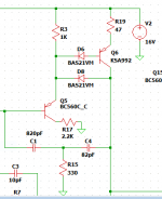
I made the changes you suggested, switching the emitter resistor to 1K and mounting a 2.2K SMD resistor on the back side of the board right on the collector of Q9. I also changed the Baker clamp to a two-diode arrangement (below) to keep the diode capacitance local to Q7. I added the same Baker clamp to the CCS. SPICE seems agreeable to this change, WRT clipping waveforms and distortion.
It seems counter-productive to put a diode in series with the base of Q7, but it doesn't seem to add much distortion, says the computer.
I have to get up the energy to take HPA1 apart and try these changes. It would be worthwhile to find out.
It seems counter-productive to put a diode in series with the base of Q7, but it doesn't seem to add much distortion, says the computer.
I have to get up the energy to take HPA1 apart and try these changes. It would be worthwhile to find out.
Attachments
Yes that’s how I’d go about it. I have not ever tried the diode in the base though.
You probably know this, but you need the base diode when you clamp around one stage, or the clamp won't turn on at all. The base-emitter drop of the first stage accomplishes the same thing if you clamp around the whole thing. The clamp diode junction capacitance is now in parallel with Cob of the second transistor. The total capacitance is still low, and isolated by the beta-enhancement first stage. The VAS is a transimpedance stage so, in principle, the base diode nonlinearity isn't a big deal. SPICE doesn't show nearly the increase in distortion with this arrangement.
The clamp limits the VAS current even without the first stage collector resistor. I'm not sure how that resistor keeps the emitter follower from oscillating. In theory, you want to add resistance to the base, not the collector, to cancel the negative input resistance of the follower. The collector resistor creates some negative feedback, slowing down the first transistor due to Miller effect around its own collector-base capacitance, dunno.
In practice though you don't need it - you can see this if you compare with just the single clamp diode and without it on a scope plot. Most Baker clamps in amps don't include the second diode in series with the transistor base. Part of the reason why this works is that the voltage across the base collector junction in saturation is limited by the clamp diode voltage due to the transistors internal base resistance and the diode dynamic resistance is lower than the small signal base resistance.
re the oscillation - see the presentation I linked to. The stray inductances and parasitic capacitances around the follower form oscillator structures - the resistor in the collector (provided it is placed close to the transistor) isolates the stray capacitances. If using a cascode, you almost always want to include some base resistance (base stopper) to ensure you don't have HF parasitic oscillation - same BTE for output transistors in the power stage. In the small signal stages, you could include some base resistance but you would have to assess this separately. Note that most Lin topology amps using a current mirror LTP load do not include a series resistor into the helper transistor base. See for example Self and Cordell for circuit examples and a fuller treatment of the subject.
(Its improtant BTW that you try to get a handle on the frequency of oscillation you have - that will tellyou a lot about the probably root cause)
🙂
I need to look at your article on oscillators again. Conventional wisdom says the emitter follower is unstable because the emitter load resistance gets transformed into a negative impedance looking into the base, and this in combination with stray base inductance and Cob turns it into an oscillator. Adding a base resistor cancels the intrinsic negative input impedance. But of course, there are other stray reactances. I will study this some more.
I haven't looked at the math behind the negative impedance analysis. Lowering the emitter resistor loads the first stage down more, reducing the feedback a little, and maybe that improves things.
With, say, 1K in the emitter of the first stage, and 1K in the collector, you have basically a split-load phase inverter (so saying, if you're into tube circuits) and the voltage gains from base to emitter and base to collector are roughly equal. The gain is less than unity, so the Miller effect is minimal, but it does create some collector-to-base feedback via the first stage Cob. I suspect this introduces a pole in the response of the first stage, compensating it, and maybe that's why the collector resistor stabilizes the device. I could be wrong about that, need to test that in SPICE (too lazy to do math).
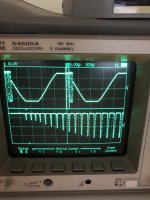
I posted this picture (below) over on my thread, but I'll show it again here. This is the amp clipping in the first version, with no clamp diodes, but a VAS current limiter transistor. The frequency is in the range of 300 kHz and I believe it's due to the global feedback loop going nuts, not the local emitter follower oscillating.
I'm not sure if I misunderstand you, or if you misunderstand me. Forget the beta-enhanced VAS and just think about a single stage with clamp. The emitter voltage is one diode drop higher than the base. For the clamp to turn on, the collector has to be one diode drop higher than the base, too. This can only happen when the collector voltage rises to be equal to the emitter voltage. So a single-diode clamp is useless to prevent saturation in this case.
Going back to the beta-enhanced VAS, the output emitter voltage is two diode drops higher than the input base, so the clamp diode has more voltage to work with. It will clamp the second stage collector at the same voltage as its base since the diode is referenced to the first stage base. This is sufficient to keep the second stage out of saturation. Since I want to clamp around just the second transistor, adding a base diode gets me the same result. The two-diode arrangement is the classic Baker clamp circuit.
There is no need for the extra base diode when clamping around both transistors as shown, for instance, on your site. The disadvantage is Miller effect makes the diode junction capacitance look several million times larger and all the IPS drive current flows into that capacitance without Cdom to swamp it.
I haven't seen any examples of the kind of clamp I proposed above used with the beta-enhanced VAS. Partly I think this is because Self and Groner strongly advise against using clamps at all, and if that's good advice, then logically, two diodes must be even worse, right?
Simulation says the two diode clamp is ok, but I don't trust SPICE, so I'm a little reluctant to commit to the new scheme before I think about it some more.
I haven't looked at the math behind the negative impedance analysis. Lowering the emitter resistor loads the first stage down more, reducing the feedback a little, and maybe that improves things.
With, say, 1K in the emitter of the first stage, and 1K in the collector, you have basically a split-load phase inverter (so saying, if you're into tube circuits) and the voltage gains from base to emitter and base to collector are roughly equal. The gain is less than unity, so the Miller effect is minimal, but it does create some collector-to-base feedback via the first stage Cob. I suspect this introduces a pole in the response of the first stage, compensating it, and maybe that's why the collector resistor stabilizes the device. I could be wrong about that, need to test that in SPICE (too lazy to do math).
I posted this picture (below) over on my thread, but I'll show it again here. This is the amp clipping in the first version, with no clamp diodes, but a VAS current limiter transistor. The frequency is in the range of 300 kHz and I believe it's due to the global feedback loop going nuts, not the local emitter follower oscillating.
I'm not sure if I misunderstand you, or if you misunderstand me. Forget the beta-enhanced VAS and just think about a single stage with clamp. The emitter voltage is one diode drop higher than the base. For the clamp to turn on, the collector has to be one diode drop higher than the base, too. This can only happen when the collector voltage rises to be equal to the emitter voltage. So a single-diode clamp is useless to prevent saturation in this case.
Going back to the beta-enhanced VAS, the output emitter voltage is two diode drops higher than the input base, so the clamp diode has more voltage to work with. It will clamp the second stage collector at the same voltage as its base since the diode is referenced to the first stage base. This is sufficient to keep the second stage out of saturation. Since I want to clamp around just the second transistor, adding a base diode gets me the same result. The two-diode arrangement is the classic Baker clamp circuit.
There is no need for the extra base diode when clamping around both transistors as shown, for instance, on your site. The disadvantage is Miller effect makes the diode junction capacitance look several million times larger and all the IPS drive current flows into that capacitance without Cdom to swamp it.
I haven't seen any examples of the kind of clamp I proposed above used with the beta-enhanced VAS. Partly I think this is because Self and Groner strongly advise against using clamps at all, and if that's good advice, then logically, two diodes must be even worse, right?
Simulation says the two diode clamp is ok, but I don't trust SPICE, so I'm a little reluctant to commit to the new scheme before I think about it some more.
Attachments
Ok, I tried some variations in SPICE just now. Some unexpected results, though they make sense in retrospect:
1. With just the one clamp diode and no base diode, the transistor saturates. But its base current is limited to a safe 5mA, because the diode steals the bulk of the current that would otherwise flow from the base.
2. With the added base diode, the transistor doesn't saturate, and base current is reduced to around 400uA.
3. In both cases, the emitter current peaks at 95mA because all the first stage current is still dumping into the second stage.
4. With the clamp around both stages, the second stage emitter current is less than 10mA. This is because the clamp is keeping the first stage from turning hard-on.
There's a lot of combinations here and no perfect solution. But it seems clear, the single diode around one transistor without a base diode is not effective to prevent saturation.
Thinking about your comment some more, I don't think the dynamic resistances are that relevant since this is a large-signal clipping situation and the devices are acting as switches.
I have only ever used the clamp with a helper so there's always 2 Vbe involved.
If you oscillation is at c. 300 kHz then its almost certainly loop related - you will need to do a loop analysis and see if you have enough gain and phase margin.
Read the presentation I linked to (see the oscillator circuits that were simmed) and read Cordell where he talks about Colpitts structures being formed in EF circuits. A base stopper is important to tame the reflected -ve base resistance, but you cannot ignore the other stuff going on there either.
- Home
- Amplifiers
- Solid State
- Subjective effect of Baker clamps