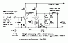
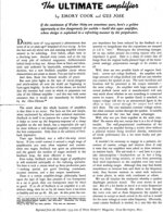
300B Amplifier kits
- By Valvetime
- Tubes / Valves
- 1 Replies
Hello all
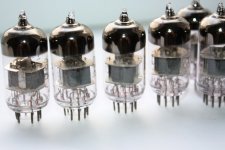
I am keen to build a 300B single ended vacuum kit - i have been looking at the Elkit 8900 with Lundal transformers.
i would appreciate advice re this kit or any other kit that would be worthy to build .
I have built a few valve amp kits now , whilst nit an expert - certainly competent and careful.
I am keen to build a 300B single ended vacuum kit - i have been looking at the Elkit 8900 with Lundal transformers.
i would appreciate advice re this kit or any other kit that would be worthy to build .
I have built a few valve amp kits now , whilst nit an expert - certainly competent and careful.


