I've got a hefty power transformer sitting around, taken from a 5-channel x 100w receiver built around 2002.
Pioneer I believe, long trashed.
I've ran some tests on the transformer, and posted my findings in the photo here.
What I'm asking for is.... if adapting to use this for a 2ch stereo amp, custom build, what would be a suitable A/B BJT design, and useful VA rating of this hunk of iron?
Pioneer I believe, long trashed.
I've ran some tests on the transformer, and posted my findings in the photo here.
What I'm asking for is.... if adapting to use this for a 2ch stereo amp, custom build, what would be a suitable A/B BJT design, and useful VA rating of this hunk of iron?
Attachments
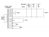
I'd say it should be good for about 3A on the main secondary windings, which would rate it at 300VA ( not including the aux windings ).
As for the proper design, any class AB single pair output devices should be fine, and there are loads of them on the internet...
I think you should choose what ever get's your attention.
As for the proper design, any class AB single pair output devices should be fine, and there are loads of them on the internet...
I think you should choose what ever get's your attention.
the 50 CT windings would be great for a LM3886 chip amp. The 100Vct winding will give you around +/-70 VDC after the rectifier unloaded. Choose carefully. When measuring the secondary drop, keep an eye on the primary side. I was working on a 500watt per channel amp @2ohms a few years ago and I noticed the secondary dropped a lot more than I expected. Then I noticed so did the primary. The Normal 122Volt AC line dropped to 105VAC. I was too far from the breaker panel and too many things plugged into the same breaker.
Not to worry.the 50 CT windings would be great for a LM3886 chip amp. The 100Vct winding will give you around +/-70 VDC after the rectifier unloaded. Choose carefully. When measuring the secondary drop, keep an eye on the primary side. I was working on a 500watt per channel amp @2ohms a few years ago and I noticed the secondary dropped a lot more than I expected. Then I noticed so did the primary. The Normal 122Volt AC line dropped to 105VAC. I was too far from the breaker panel and too many things plugged into the same breaker.
My service bench is less than 30 feet from the mains box, and on it's own breaker.
I get a normal 120-123vac at the bench.
Lm3886 is nice and simple for obvious reasons but the maximum, no signal supply voltage is a total 94V i.e. +/-47VDC, unloaded. A comfortable maximum for pushing only 8 ohm loads would be +/- 40V. Realistic speaker loads down to 3 ohms suggest +/- 35VDC or so. Happily, the transformer's main windings are 25VAC each and surely they can be arranged to suit a stereo amp. I imagine it would be a great start for a nice, easy-build and reliable amp.
Even so, this is the solid state (read discrete semis) forum and I'd be looking for medium power amplifiers - not the obligatory 100 - 250WPC size favoured by our resident design experts. I can't find a reason for more than 20WPC myself but that depends on what you want to do with your amp - e.g. personal entertainment, quiet evenings with friends, frighten the pets, irritate the neighbours, show off your DIY skills or play conductor of the orchestra at full volume for the fun of it. There's so many suitable designs here, going back many years but right now, I would venture into new territory with Bonsai's recent KX amplifier for DIY. It's very well documented and supported both here and at his his own website, with the option of class A operation if desired. https://hifisonix.com/hifisonix-kx-amplifier-v2/
Even so, this is the solid state (read discrete semis) forum and I'd be looking for medium power amplifiers - not the obligatory 100 - 250WPC size favoured by our resident design experts. I can't find a reason for more than 20WPC myself but that depends on what you want to do with your amp - e.g. personal entertainment, quiet evenings with friends, frighten the pets, irritate the neighbours, show off your DIY skills or play conductor of the orchestra at full volume for the fun of it. There's so many suitable designs here, going back many years but right now, I would venture into new territory with Bonsai's recent KX amplifier for DIY. It's very well documented and supported both here and at his his own website, with the option of class A operation if desired. https://hifisonix.com/hifisonix-kx-amplifier-v2/
Interesting
would provide +/_ 70v rails and +/_ 35 rails
+/_ 35 sounds about right for 90 to 100 ish watt amps @ 4 ohms
Not sure if the original amp had 2 rails because it was class G or H
or if it used higher voltage for driver stages to get more power from mosfets
would provide +/_ 70v rails and +/_ 35 rails
+/_ 35 sounds about right for 90 to 100 ish watt amps @ 4 ohms
Not sure if the original amp had 2 rails because it was class G or H
or if it used higher voltage for driver stages to get more power from mosfets
The main amp and outputs were powered off the +/_ 30v and +/_ 65v according to schematic.Interesting
would provide +/_ 70v rails and +/_ 35 rails
+/_ 35 sounds about right for 90 to 100 ish watt amps @ 4 ohms
Not sure if the original amp had 2 rails because it was class G or H
or if it used higher voltage for driver stages to get more power from mosfets
The other windings were for other areas of the home theater receiver.
This transformer was powering 2 Pioneer amp "hybrid IC modules", PAC010A-PAC011A one a 2 channel, the other a 3 channel.
All channels listed as 100W. - front-rear-center.
It might be class H, but it also might just be running the surround channels at lower power. If you didn’t want to mess with a class H circuit, you could use it for a 4 channel bi-amp amplifier. Don’t need full power for tweeters.
Many multichannel receivers are using these two voltages for switching to a lower voltage rail when selecting the lower impedance option in the settings to keep itself alive...
Not this one.Many multichannel receivers are using these two voltages for switching to a lower voltage rail when selecting the lower impedance option in the settings to keep itself alive...
If that were the case the voltages would differ by a factor of the square root of two, to get the same power at 4 and 8 ohms.
Based on the observed voltage drop into your test loads, it is a 400-500 VA trafo. Good for about 180 watts at 8 ohms, out of a single channel. Loaded down with two channels you’re probably looking at 120 each. Three would probably drop below 100 if it were honestly measured.
Based on the observed voltage drop into your test loads, it is a 400-500 VA trafo. Good for about 180 watts at 8 ohms, out of a single channel. Loaded down with two channels you’re probably looking at 120 each. Three would probably drop below 100 if it were honestly measured.
Here is one of the (hybrid) output amp IC's showing the use of both "taps" of the B+ feeds - the +-30v )(VLow) - and the +-65v (VHigh)If that were the case the voltages would differ by a factor of the square root of two, to get the same power at 4 and 8 ohms.
Based on the observed voltage drop into your test loads, it is a 400-500 VA trafo. Good for about 180 watts at 8 ohms, out of a single channel. Loaded down with two channels you’re probably looking at 120 each. Three would probably drop below 100 if it were honestly measured.
Now this is the 2 channel chip, there is also a 3 channel chip wired the same way.
Spec sheets of these chips all rate the outputs at 100w.
Whether the transformer could deliver full power 500w from these chips is up for discussion.
However, I doubt many people are that deaf to need 500w from a home theater system continuously.
That looks like the modules are probably a class H circuit. There really isn’t anything magic about it, but it does reduce the heat that is produced, especially at low power levels and typical “very loud” listening levels. Going class H does not reduce the transformer size requirement to get X number of watts by any significant amount since the maximum efficiency goes from 78% to 87.
in most applications, pro or home, the transformer is sized VA-wise for the typical maximum listening levels. The only difference is whether that is 1/3 power (on average) 1/8 power, or something even less. In any case, push it harder and it overheats after many minutes to an hour. But what that does do is give you relatively poor regulation if it’s only sized for very low duty cycle - the voltage drops like a stone under load. +/- 65 volts is pretty damn high for just 100 watts per channel. They used less voltage in the Crown DC300 to get 150, but that was a 600 VA trafo. If the power ratings were real in this receiver, that supply would drop to +/-46 at full output - and even worse if it’s a “one channel driven” rating or other similar bull. While you only get 100 watts, the peak voltage and current stresses in the amp are those of a much bigger amp. And it only takes tens of milliseconds to get transistors to go into second breakdown. Load impedance gets too low and bang, even if the average output is relatively low. Class H only helps out to a limited degree, because the peak voltage and current stresses into a resistive load don't change by much compared to regular class AB. Into reactive loads it is tremendous help, and it does keep heat down and heat accelerates all failure mechanisms.
in most applications, pro or home, the transformer is sized VA-wise for the typical maximum listening levels. The only difference is whether that is 1/3 power (on average) 1/8 power, or something even less. In any case, push it harder and it overheats after many minutes to an hour. But what that does do is give you relatively poor regulation if it’s only sized for very low duty cycle - the voltage drops like a stone under load. +/- 65 volts is pretty damn high for just 100 watts per channel. They used less voltage in the Crown DC300 to get 150, but that was a 600 VA trafo. If the power ratings were real in this receiver, that supply would drop to +/-46 at full output - and even worse if it’s a “one channel driven” rating or other similar bull. While you only get 100 watts, the peak voltage and current stresses in the amp are those of a much bigger amp. And it only takes tens of milliseconds to get transistors to go into second breakdown. Load impedance gets too low and bang, even if the average output is relatively low. Class H only helps out to a limited degree, because the peak voltage and current stresses into a resistive load don't change by much compared to regular class AB. Into reactive loads it is tremendous help, and it does keep heat down and heat accelerates all failure mechanisms.
So now, if this receiver is rated to deliver 100wx5 channels, and is some class H design, then it seems that I can use it for a class A/B 2x100w with good results.
The primary and secondary windings are visible and appear to be quite thick, so regulation/sag should be of no concern.
According to my testing, a +/- 35v resulting in a trivial drop at 4 amps is quite good.
The primary and secondary windings are visible and appear to be quite thick, so regulation/sag should be of no concern.
According to my testing, a +/- 35v resulting in a trivial drop at 4 amps is quite good.
If you crack open the transformer end covers, you may find you can split the outside windings and get a pair of 50 VCT windings from them. You would wind up with a pair of 50 VCT windings and be able to use the transformer to full potential if you are looking for +/- 35v.
This transformer doesn't have end bells.If you crack open the transformer end covers, you may find you can split the outside windings and get a pair of 50 VCT windings from them. You would wind up with a pair of 50 VCT windings and be able to use the transformer to full potential if you are looking for +/- 35v.
The windings come out to wire-wrap type pin connectors on terminal strips.
GOOD!!!!!
IF all windings are independent, joined only at the PCBs you show, then you have many more possibilities.
I would remove the PCBs and measure all windings, then make a "map" and post it here.
Unrelated comment:
in THIS particular thread, NO annoying "similar posts" spacewaster suggestions.
Do you have a special agreement with the Gods or something? 😉
That photo was of an identical trans, mine's already been stripped of the PC boards.GOOD!!!!!
IF all windings are independent, joined only at the PCBs you show, then you have many more possibilities.
I would remove the PCBs and measure all windings, then make a "map" and post it here.
Unrelated comment:
in THIS particular thread, NO annoying "similar posts" spacewaster suggestions.
Do you have a special agreement with the Gods or something? 😉
Unfortunately, the bobbin mounted terminal pins are difficult if not impossible to manipulate the windings into being separated.
The secondary in question is thick 16 gauge solid wires and partially buried in the bobbin.
I'll have a closer look when I get the time, but would hate to ruin the durability of those connections.
This shows the 2 hybrid IC's and layout before I tore the whole thing up for parts.
As for the "gods" of anti-subjects and disruptive topics, I don't know why they seem to favor me, I'm already a god of sorts.
Ask my previous customers. 😉
- Home
- Amplifiers
- Solid State
- Power Transformer specs