USB stick digital audio to analogue.

I have a 1960s large cabinet valve radio, I also have a collection of 1950s and 1960s music in flac format (can convert to mp3).


What I am looking for is something to plug a USB stick of music into that has analogue output that I can plug into the PU socket on the back of the radio.


Object of the exercise, to play 50s/60s music through 50s/60s equipment as unsurprisingly there are no radio stations playing that content these days.


I can find lots of DACs, but none that have USB input. Does anyone know of such a device?

Parts shortage

Has any one else felt the parts shortage such as Mouser and Digikey. Yesterday I checked on NE5532 through hole and they were out and not expected back in stock till 5/18/2022 and this is just one example. Of course they can be found on Ebay from sellers but why are the large parts stores out with long waiting times?

Kemet ALC10S Slit Foil Capacitors - Any Good?

Hi Everyone,

Anyone experienced these Kemet ALC10S capacitors for power amp PSU?
These are the 2 pin snap-in type and not those 4-pins T-network.

I’m looking at 10,000uF 63v for my solid state amp. Problem is the data sheet has no information on their ESR and I get no response from them on my email to them.

I would love to have the Sikorel ones but they are just too expensive.

Thanks

Yaqin MC13s coupling caps upgrade

Hello,
I'm debating whether or not venturing into changing the four coupling caps to my Yaqin MC13s. I would like to get a flatter response, a bit more midrange presence, as compared to my Kenwood KA7300 the Yaqin produces a slightly scooped response... Do you think caps would make a difference in that respect?

I don't want to spend more than €10 per cap and was leaning towards Audyn cap plus, but they are too big to fit! 🙁 2nd option was Jantzen Superiors but I've seen even Troels Gravesen (who seems to know them very well) is not so convinced about their use as coupling caps. so I'm ditching that option too

Other options?
-Russian PIOs k40s/k42, I fear they might as some say act as a filter and while giving a pleasant midrange response they may cut bass/treble
-K71-4 polystyrenes
I wonder if somebody has changed caps to this or similar amps and can share their experience.
Thanks

DCB1 Black, White and Red Kits

THESE ARE CURRENTLY NOT AVAILABLE, DEMAND has been low.

I have put together some full kits designed to complement the DCB1 black edition boards.
This includes Black resistors and caps, red caps, some white lettering and whatnot.
OK, so it's a cosmetic thing, but I realize this is important to a lot of people. (myself included)


Here is the rundown.
120 dollars for the kit +
25 for board
8 dollars domestic and 24 dollars international first class shipping.
The kit is not the whole deal - no chassis, wires , transformers, and anything that is not listed. It is all the parts that populated the board.
DCB1 Black, White and Red kit BOM
Sometimes small substitutions are made.

1-Relay diode 512-1N4001
2-10R Dale 3.5W
2-5R Dale 3.5W (alt)
1-TO-220 Heatsink for 7812 532-6237B
3-Nichicon Muse KZ 100uf 25v
1-BC517
2-BC550C
1-BC560C
4-MSRF860 Diodes
1=7812 slow start regulator
1-relay bypass cap 505-MKS02.1/63/10
1-Relay TQ2-12V-3 or equivalent
2-header male
2-header female
10-header pins
2-IRFP240
2-IRFP9240
1-connector block 3 pos 571-1776119-3
4-Nichicon Gold Tune LKG 10,000uf 35v
2-Wima MKP10 .22
2-47.5R Vishay Dale CMF55 .25W Resistor
2-100R Vishay Dale CMF55 .25W Resistor
4-470R Vishay Dale CMF55 .25W Resistor
1-2.2K Vishay/Beyershlag .6W Resistor
1-10K Vishay/Beyershlag .6W Resistor
1-47k Vishay/Beyershlag .6W Resistor
4-221R Vishay Dale CMF55 .25W Resistor 0.5%
2-221K Vishay Dale CMF55 .25W Resistor 0.5%
2-1M Vishay Dale CMF55 .25W Resistor 0.5%
2-1R Vishay/Beyershlag .6W 50PPM Resistor
1-Matched quad Toshiba 2SK170BL
6-Random Toshiba 2SK170BL
17-Red 20ma matched LEDs

Here is a build guide another member did.
It is excellent, and on Audiocircle. Thanks Wushiliu

DC-Coupled B1 Buffer Build

Consider also the following Salas In-Select board and kit for a selector and volume control input.

GB For Salas I-Select Mesmerize Type input selector and volume control - diyAudio

Attachments

  • dcb1black.jpg
    dcb1black.jpg
    252.1 KB · Views: 6,499

A fistful of Monacor SP-200X

I got an urge to build a crazy box with fullrange-drivers since I have never fiddled around with any. Since I work at Monacor, it's quite economical for me to use monacor drivers. 😉

The project I had in mind was a big box with 6pcs of SP-200X (8inch fullrange speaker). When I simulate in winisd I get unusual (for "normal" drivers anyway) results. It seems I need a HUUUGE box to make them go low. Also I have a "bump" on the line which I would like to get rid of without a 680liter box (that size actually makes lovely similations). Is the "bump" just a simulation error or is this common for some fullrange speakers?

If a 600 liter box is what it takes then 600 liters it is, but I would like a smaller box if it's possible.

Attachments

  • bump.gif
    bump.gif
    11.3 KB · Views: 1,620

NAD C320BEE distortion

Hi, been a long time since I posted, but here goes.
This amp appears to work normally, but music through both channels sounds mildly distorted at all volumes, sounds like low-level clipping as if a component is not getting enough voltage. As the fault is identical on both channels, I was inclined to suspect faulty supply rail or associated components. Fuses check ok and the soft clipping switch makes no difference. In fact I isolated the issue to the power amp stages by removing the pre-main links and feeding input direct to the main amps, starting with a low volume and stepping it up - result the same,distortion at all levels..
Measuring the rectified power supply to the main board, it comes in at a stable +/- 51V, which is a little above the 47V spec.
But measuring across the speaker terminals I get an fluctuating DC offset of 0.27 to 0.3V on both, obvs far too high but apparently not enough to trip the protection.
Any steer as to what can be causing this? Is the distortion linked to the DC offset?
I did squirt some deoxit around the trimpots and gave them a tweak back and forth (equally , to arrive back at the original set point) but this seemed to have no effect.
I don't have a scope, just a pocket meter , a soldering iron and a schematic.
It's a good amp and It would be nice to get it back.
kind regards, folks, keep up the good work

Linear PSU's, torroids, power amps, almost free,(UK) good for purifi PSUs?

So to be clear, by free I mean cover my costs and time, or I'll just take it to the skip.

All parts taken from a pair of Denon AVC A11SR amplifiers and AVC A10 SE; power rails for amplifiers are meant to be +/0/- 63V. quoted as 0.05%THD. Rated to 125w 6-16 ohm.

I have:
Power amplifier boards -
FROM 1st A11SR:
4 channel power amp board - should be fully working
3 channel power amp board - should be fully working. One cable from output to PSU had to be cut due to binded/cold welded screw.
Same again from 2nd amp except at least 2 possibly 3 channels have blown transistors from messing around.

A10SE power amplifiers are a single 5 channel strip, should be working fine.
All come mounted on heat sinks.

Power supplies - note some wires cut due to rounded screws, nothing a good bit of electrical engineering can't fix easily.
2 large linear boards from the A11SR's. oddly these have the video RCA connectors on the same PCB at the back!
One pair of caps is domed and should be replaced.
Main caps are 18000uF 71V 'Denon Audio' branded.
Have also removed smaller boards that supply DSPs/Pre amps etc

Toroids - rated at about 600VA (guessed from specs) shielded audio toroids. Note that this represents a tear down of what used to be £5000 in amplifier!

All power supply and amplifier boards in a single box for £50.

Toroids I'd rather keep, but I know I'm likely just to leave them in a drawer never to see daylight.
Add £30 for the AVC A10SE toroid.
Add £80 for BOTH of the AVC A11SRs toroids

Reusing my speakers?

Hello community.

I have no idea if I'm at the good place, so feel free to move the topic.

I have a pair of SEAS MIMIR that I have been using since 2011. They work very well and I'm kind of happy with them. Kind of, because with such a low sensitivity, they are lazy at low level and need to be pushed hard to give all they have.
I have an ATOLL IN100 to provide the power 2x100W @ 8ohm)

Well, it was my first (and only so far) audio DIY project. Pictures coming soon, of course.

As I am going to move in a bigger house I would like to reuse the speakers (27TDFC and CA18RNX), and add some if needed, to build a 2, 2.5 or 3 ways speaker in a larger cabinet.

Thanks for your help 😉

Failing Martin Logan SW10 Amp

These pix are from a Martin Logan SW10 amp board which is buzzing when turned on (goes away after awhile) and distorting during operation. Clearly something has gotten very hot. Seems like it is the two Blue resistors. One charred the PCB and the other was touching the Red output and blackened the shroud around the spade connector. I don't think there was electrical connection.

This is probably a generic chinese amp which is branded for ML.
PCB code is PCBPBDR818R 2007.04.17 Rev 1.6

Does anyone happen to know of schematics or can take a guess at what the root cause is? The main capacitors don't seem to be puffed out on top but I will try to remove and test.

Attachments

  • SW 1.jpg
    SW 1.jpg
    416.8 KB · Views: 114
  • SW2.jpg
    SW2.jpg
    495.2 KB · Views: 107
  • SW3.jpg
    SW3.jpg
    448.6 KB · Views: 99

  • Locked
The Well Tempered Master Clock - Building a low phase noise/jitter crystal oscillator

I start this thread to investigate the opportunity for a diyer to build a real low jitter oscillator.

The great issue for a diyer is that typically he doesn't own the suitable gear to test the performance of an oscillator, so the results are uncertain.
The equipement to test the phase noise of an oscillator starts from some tens thousands dollars, and a diyer can't afford them.

The true guru in this matter, that you probably know as Jocko Homo, has demonstrated that one could build a low phase noise oscillator taking a crystal from the shelf with a simple pico gate. He did reach -122 dBC@10Hz from the carrier for a 11.2896 MHz oscillator, that's an impressive result.
But he did a strong selection of the crystal using a phase noise measurement system that costs 30,000 USD or more.
Moreover the crystals he had used, around 0.5 USD each from Mouser or Digi-Key, are no longer manufactured, and the supplier don't have anymore in stock. They were the cylinder crystal CSA309 from Citizen.
He also tested the HC49 type, but seems it's not perform like the above type.
You have to consider also that after the selection, only a few crystals can reach similar performance when placed in the oscillator, usually not more than 5%.
The other crystals were throw out, so the cost increases.

That's the reason I believe the goal is to start from a very good crystal, with high standard and repeatable features.

I will experiment with 3 kind of oscillator circuit to implement the above crystal: the Clapp crystal oscillator, the Butler two emitters, and the Driscoll.
The first oscillator is almost ready, with its own PCB, then I'll investigate the other two.
In the second and third circuits, the crystal see a very low impedance, and this usually guarantees a very high loaded Q.

When all the circuits will be ready, I can access a university lab to test them with an Agilent phase noise measurement system.


TWTMC project. For Schematics, BOM, PCB and Assembly guide see post #1506
The Well Tempered Master Clock - Building a low phase noise/jitter crystal oscillator

Group buy thread for this project is located at
The Well Tempered Master Clock - Group buy - diyAudio

New oscillators, frequency doublers and sine to square converters from post #3008
The Well Tempered Master Clock - Building a low phase noise/jitter crystal oscillator

Semi-finished boards BOMs update at post #3482
The Well Tempered Master Clock - Building a low phase noise/jitter crystal oscillator

User manuals
The Well Tempered Master Clock - Building a low phase noise/jitter crystal oscillator

Sanity check: KT88 PP design

Alright, I'm just about to take delivery of my power transformers so it is about time to heat up the ol' iron and start putting this design together. Apart from doing the calculations on a piece of paper using a freshly sharpened pencil I've simulated pretty much every aspect of this design and by the looks of it she should work.

However I'm a mere human, so I err every now and then, or make (in hindsight) dumb design choices, so I would appreciate an extra pair of eyes check this design over before I dim the lights on the whole street when I flip the power switch. Comments and suggestions are welcome, lets hear it gentlemen! Thanks! 😀

Attachments

  • schematic_simple_kt88pp_019_6922eh.jpg
    schematic_simple_kt88pp_019_6922eh.jpg
    952.3 KB · Views: 296

Technics SL-1301 running 1% fast

Hello All,
I recently purchased a Technics SL-1301 with a jammed 45 selector switch that I managed to fix. While testing the turntable for any other issues I discovered the reference strobe app on my smart phone wasn’t synching with the turntable’s strobe which is supposed to be locked at 33.3333. rpm. I adjusted my phone strobe speed to 33.666 and it synced with my turntable strobe light. As it turns out this turntable doesn’t have pitch control pots. For further reference I played the same song from vinyl and an online steaming source. The vinyl slowly out paced the streaming source. I’m trying to figure out if a +1% drift is common for quartz locked turntables. I’ve read that the reference crystal frequency may drift over time, and this turntable is over 40 years old. Otherwise, the turntable runs great and holds steady with a surprising amount of drag. Any help is appreciated. Worst case scenario is I’ll have a little more free time from my vinyl 😉.

Attachments

  • IMG_8744.jpg
    IMG_8744.jpg
    615.2 KB · Views: 299

Hafler DH-110 Tone Control Pop

Hello all. Before I throw in the towel on this problem, I thought I would run it by all the pros here.
What I have is a Hafler DH-110 preamp that has a loud pop when the tone circuit is activated. I have checked out all passive components and replaced all transistors with matched models.
Its a simple baxandall circuit that is either is in the feedback circuit or around it. A tone filter also ties the circuit to ground. Thos caps are fine.
Pressing the tone switch slowly can bring about -21.00v spikes as noted in the schematic attached.
My guess is that it is inherent in the design. Even the manual makes mention of spikes if the button is pushed too slowly.
Even pressing the button quickly results in quite a pop if hooked up to a power amp.
Muting circuit Fets are new, nothing weird there.
Thank you all for looking

Attachments

  • DH-110-tone11.jpg
    DH-110-tone11.jpg
    114.4 KB · Views: 433

What are the real advantages of ACE bass?

Hi,

The ACE bass system is often mentioned as a servo system but its not. A servo corrects the motion based non linearity whereas the ACE bass system puts the resistance of the voice coil in the feedback circuit thus minimizing the effect of the impedance of the voice coil.

So, what are the real tangible advantages of the ACE bass system and at what bandwidth?

Thanks and Regards,
Goldy

A quick tip for soldering multiple connectors

Hi All

Here's a good tip if you are soldering multiple connectors of the same type - say RCA/phono plugs for example.

Always buy one of the opposite polarity of connector - for phono male plugs some form of phono female socket - I use a solid female to female phono connector.

Put the female in a vice to hold everything steady and plug the male into it while soldering the connection wires. If the plastic in the male connector is a bit soft and starts to melt, the female will keep everything in line until the plastic cools - this is especially good when soldering DIN plugs and the plastic always seems to melt a bit no matter how good they claim to be.

When you have finished soldering one plug, just unplug it and plug the next one in to the female and away you go.

Cheers

Mike

Help with first Speaker build atmos speaker

Hello everyone! I need YOUR help. I'm trying to design an atmos speaker that goes in the corner of our tv room. It's my first speaker build.
I would like to use the CNote Drivers and perhaps even the same crossover.

Explanation here.

Also, if it is adviseable to use the Cnote drivers, how do I go about figuring out how to space them (the holes for the drivers on the baffle) exactly as they are spaced in the Cnote?

2021-11-10 15-59-19 on Vimeo

Any current mode Class D ICs?

Question:

Is there is any current mode (high output impedance) class d IC at all by a reputable manifacturer or are they all voltage sources with low output impedance?

Background:

I want a current mode / current source / transconductance amplifier: I.e. high output impedance of 200 ohms or more.

Class D efficiency would be nice and I don't need a lot of power, 10W @ 8 ohms is plenty so ICs like the TDA8932 would be perfect if it wasn't a voltage source.

I have tried to wrap a current feedback loop around the TDA8932 but it doesn't work. I can push the output impedance up to ~ 10-20 ohms but it becomes unstable. It rests on the knife edge where if I change the output resistance or use a bit more feedback it starts to oscillate at full power.

Resistor lead diameters?

I ordered an assortment of 1/4-watt metal film resistors via Amazon maybe a couple of years ago. They measure (value-wise) and are labelled appropriately.

The only thing is, the leads are awfully thin. Approx. .3mm. I'm accustomed to slightly thicker leads, typically around .45mm.

It hasn't been a problem until now, I'm modifying a cheap phono preamp so I can change the loading resistors. I purchased some inexpensive sockets on Amazon that work great with everything but these resistors, the leads are just too small for the sockets to grip.

So I figured I'd just order a small assortment of resistors via Digikey, but was wondering if I'd run into the same issue. Is this something others are seeing, should I increase the wattage to 1/2-watt?

Or do I just have some cheap, non-conforming resistors, and others ordered via Digikey will be safe?

Any stand-out brands @ Digikey which may have a more hefty lead?

Thanks in advance for any help.

How do I delay a signal for a speaker in a crossover?

Dear all,

I've built a part of 2-way Synergy-style horns, and am currently musing on how to manage the crossover/delay requirements of the speaker as a single unit.

I saw in this thread that opamps or bucket bridge devices could potentially be used in an analogue setting, but I wanted to ask to see what other designers and builders have done, with success.

For this, I'm looking for a small delay, somewhere between 0.4 and 0.6 milliseconds.

While it's relatively easy to do this using a PC-based DSP, additional system latency is a factor, so I thought I'd try looking at an analogue solution to minimise that.

Thanks in advance for your help and thoughts!

Memphis 16-MC1000D Ground Short (Newbie 1st Post)

I'll start off by mentioning this is my first attempt at repairing an amp.

Much of what I've learned has been from Perry's free tutorial and watching some videos by BareVids. I'm not completely versed in all the "lingo" but I have no issue stepping back and doing some research to understand better.


The amp in question was going into "protect" and immediately shutting down.
I tracked down the issue to a faulty repair by a tech years ago. In which he switched the order of the op-fets/transistor? They placed the IRF640's on both banks at the front and end of the bank. ie: (640,9640...9640,640)

I removed all the op-fets as they were shorted and replaced all the power transistors.
After this I was able to power up the amp without going into protect using both 9V/12V. I then began to check the rail voltage for each back without the op-fets and drivers. I was reading with both a "budget" oscilloscope and a DMM.

With oscilloscope: +53.54V and -47.86V
DMM: +56.5V and -56.5V
On both banks

This is where my issue starts. While checking the voltage on the TL494CN pins I managed to get a reading from pins 6-10 but as I was trying to read pin 5(Oscillator) I could hear a "whining" being emitted from what I believe is the transformer on the power side. I essentially held it on too long and the fuse fault kicked on and the amp powered off. I did try to restart but no luck. I was able to determine a short to ground as when I check for continuity between +12v and GND my DMM "beeped". I also have no continuity between REM and +12v. I did all this with the power driver installed and removed.
I found that if I remove the 2x 40a fuses I would not get a continuity "beep" between +12, REM, and GND. Now I'm not too sure how to proceed in finding this short. Any help would be greatly appreciated.

IC# TL494CN
Pin 1: N/A
Pin 2: N/A
Pin 3: N/A
Pin 4: N/A
Pin 5: N/A
Pin 6: 3.62v
Pin 7: 0v
Pin 8: 11.71v
Pin 9: 4.48v
Pin 10: 4.48v
Pin 11: N/A
Pin 12: N/A
Pin 13: N/A
Pin 14: N/A
Pin 15: N/A
Pin 16: N/A


My tools:
Budget Solder Iron and Solder Sucker
Aukuyee Q15001 Digital Oscilloscope
UEI DM383B DMM

My_Ref Fremen Edition GB (14th GB)

Preface

Boards from this GB will be a new revision and could have a different BOM, don't buy parts until confirmation by me on this thread.

To keep prices lower in case of a small number of participants, up to 20 kits, PCBs will be produced in China.

From 20 kits and up PCBs will be produced in Italy as in previous GBs.

There will be, for whom is afraid of SMD soldering, the option for boards with SMD parts already hand-soldered with ROHS silver solder, thoroughly cleaned and visually inspected for 50€ more per kit, including SMD parts (a 20€ value).

If interested please PM me your PayPal associated email address and fill your nickname, country (2 letter code), number of kits and smd option on the Google Spreadsheet (please leave blank the 'PP account sent' column, I'll fill it so you have a feedback that I've received your data)

June 2020, 28 price will be fixed and I'll start sending PayPal Invoices, all payments are due by July 2020, 4.

Until PCB order from manifaturer is done it will be possible to partecipate to the GB

Boards will be ordered by July 2020, 5 and should be in my hands in 15-20 days, then packaged and shipped in a week or so.

Now the usual (updated) opener
:

The My_Ref Fremen Edition is a variation of Mauro Penasa's My_Ref with this goals:

  • a more stable and performing amp using SMD parts
  • raise LM318's PS voltage thanks to a voltage limiter
  • better PS for LM318
I've designed a brand new PCB with these features:

  • bigger caps (16mm diameter with both 7 and 5 mm pads) for C1, C2, C9
  • large use of SMD components
  • quite all small caps and some critical resistors are still through-hole
  • very small paths thanks to SMD
  • ground planes design
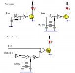
  • zener limiter based on schematic 5b from this link (which seems pretty similar to My_Evo one)
  • CCS shunt PS for the LM318
  • An alternate C9/R10 arrangement
  • Different grounding
  • Different compensation
  • a double diode bridge like in most gainclones
Both PCB and schematic have been tested organizing beta and release candidate mini group buys

I've been authorized by Mauro Penasa to proceed with this My_Ref derivate amp.


You can find references on development, beta and release candidate here:

My_Ref Fremen Edition - need help on PCB evaluation - diyAudio
My_Ref Fremen Edition - Beta build/Fine tuning - diyAudio
My_Ref Fremen Edition RC - Build thread - diyAudio
My_Ref Fremen Edition - Build Thread

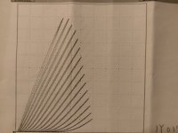
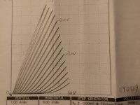
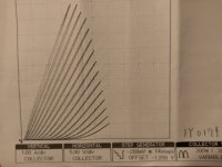
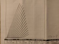
KSTR's measurements on beta boards (final boards measured a tiny bit better but almost the same performance):


7th run boards measures even better (Measure by JosephK):


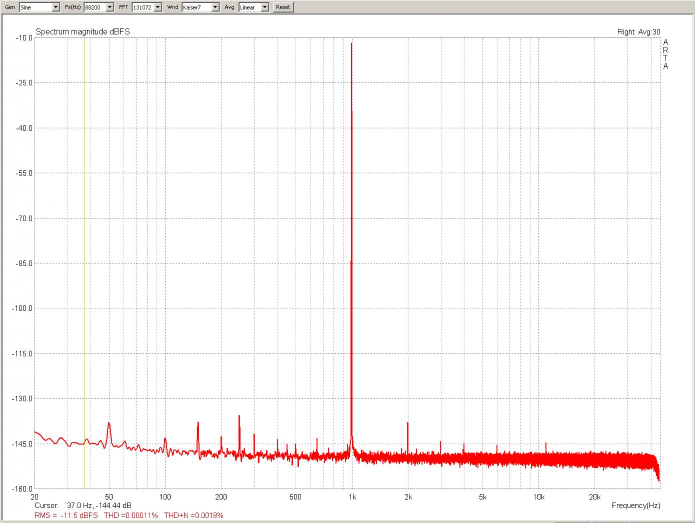
Distortion goes down ten times Vs. Beta (and previous) Boards

On my OneDrive you'll find:
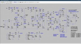
  • Schematic
  • BOM
  • Build Tutorial

And a YouTube video on SMD soldering of FE modules.

Mouser shared projects (order 2, each project is for a SINGLE board):
Industrial BOM
Industrial BOM without SMD parts
Industrial BOM + Evo A Mod
Industrial BOM + Evo A Mod without SMD parts


Actual price will depend on number of partecipants/kits, the Group Buy is about PCBs only, with an option for SMD populated ones.

Approximate price is 25-27€/Kit (one kit = 2 PCBs, PayPal fees and 1€/kit donation to DIY audio included):

Actual price will be calculated and fixed before ordering boards and it will lower as kits numbers goes up.

Shipping prices will be (up to 2 kits, more than 2 will be calculated):

Italy 10
Europe 14,50€
Rest of the world apart Oceania 18,50€
Oceania 20€

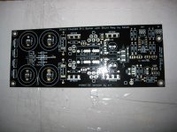
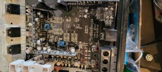
PCBs (circa 12 x 10.5 cm) will be blue, 2mm tick, 2 Oz/70um copper, gold plated, made in Italy (from 25 kits) or in China (up to 24 kits).

One transformer 160VA-300VA will be needed for each board (monoblock design)

BOM cost is around 67€ per board (premium industrial BOM) which can be lowered to 53€ (On a budget BOM).

Build a complete amp (premium industrial BOM with case, connectors, cabling, transformers etc.) will cost around 400€ and up.

Greetings:
Mauro Penasa (R.I.P.) for his great design and kind permission
LinuxGuru for his help on new compensation
Luka for the LM318 PS initial design
KSTR for the new C9, R10 arrangement.
Soongsc, Marce, Sebaastian, KSTR and Metal for help on PCB design
BMCBob for all support, tests and reviews
JosephK for his measurements and advice on further reducing distortion.

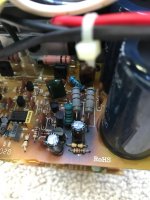
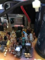
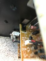
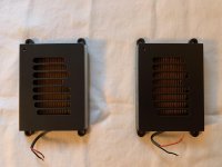
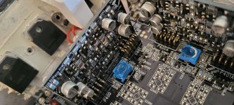
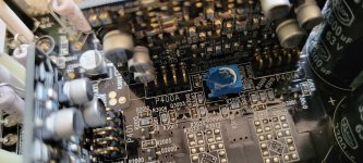
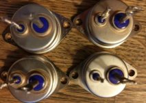
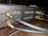
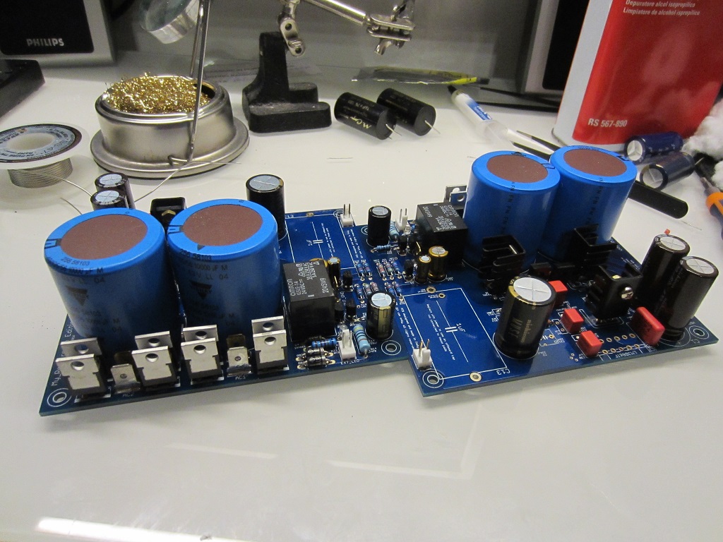
Images of boards from the 7th GB:
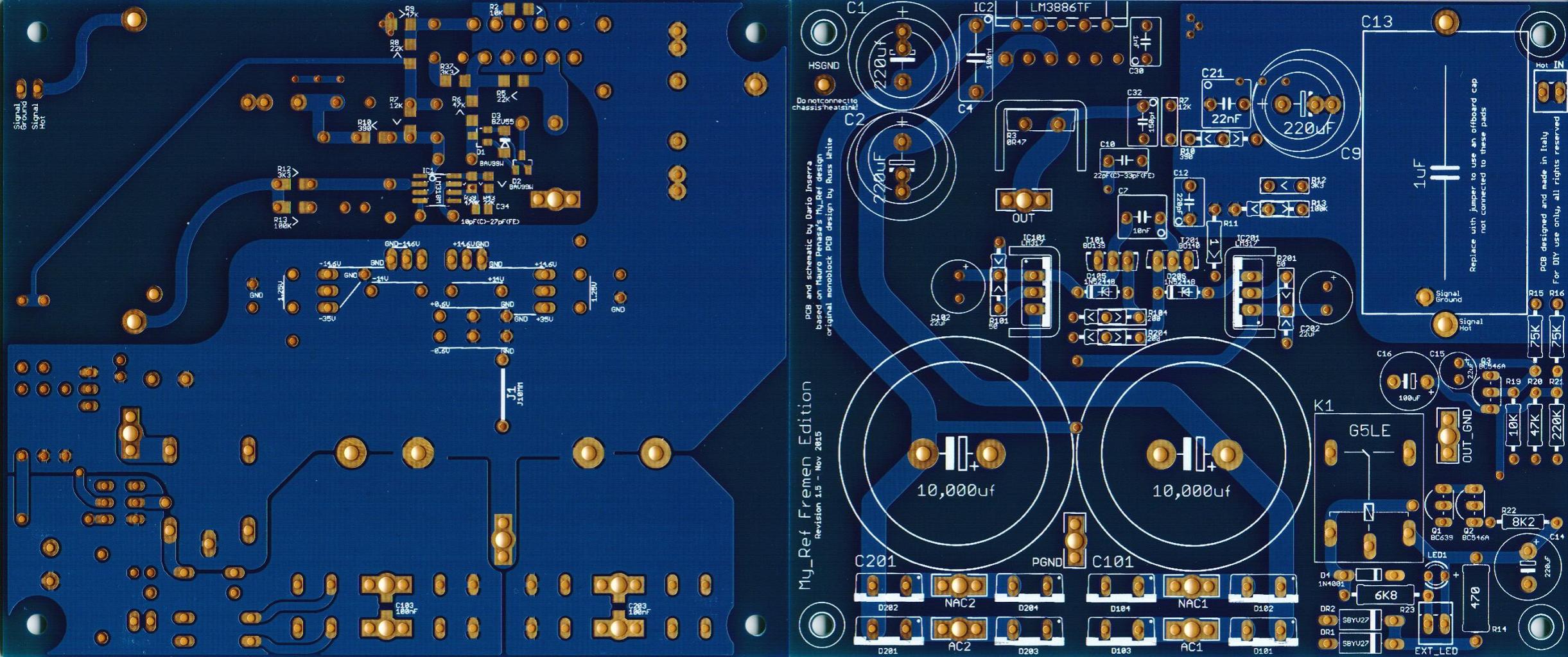

__________________

Dali Skyline 1000 restoration

Hello.
I have bought a pair of Dali Skyline for restoration, but there is almost any info over there.

Cabs are in quite good shape, as well as crossovers that seems to be in good and original condition , but fuse protection for ribbons are lost.

Tweeters seems to be well. The ribbons must be tensioned

Midranges looks well

Woofers needs surround replacement. Searching on the web I have found that those are 12" Cerwin Vega XL12S although they should have some mods.
They meazsure 3,1 Ohm and 1,1 mH

I would really appreciate any info about these speakers: Parts, replacement parts (I'm in doubt if woofers are working good), tips, mods... whatever info I can get would be really nice.

KT88 push pull cathode follower?

Alright, I'm clearly having a brain fart and I've probably been staring at it for too long, hence this post! 😱

I want to configure a KT88 push pull output stage as a cathode follower, see attached LTspice schematic. To the right is a conventional configuration, which obviously works fine (see plots above it) to the left the cathode follower configuration as I *think* it should be connected, but as you can see from the plots above it something doesn't work as planned. Which one of you fine gentlemen (ladies?) wants to help me out and get me on the right track?

Thanks! :cheers:

Attachments

  • kt88_pp_cathode_follower.jpg
    kt88_pp_cathode_follower.jpg
    506.2 KB · Views: 488

12V trigger when audio on I2S bus

I'd like to add 12V trigger to a Khadas tone board when the DAC is receiving audio over SPDIF. I'm planning to use a standard optoisolated relay board for the 12V trigger; I just need a way to trigger the relay.

Right now, I have access to the I2S bus from a 30 pin FPC connector. My question is, how can I trigger a low voltage relay when audio is coming over the I2S bus? I started poking around w/ my DMM and don't see any major voltage changes when the music is playing or paused. I'm looking for a solution in the $5 worth of parts range.

Thanks for your thoughts.

proper grounding and shielding in i2s connection

Hi, guys!

I have been having a problem with 2 of my DIY DACs for an extended period of time. The problem was with i2s connection btw a DAC board and a spdif to i2s converter in one case and USB to i2s converter (I2SoverUSB) in another case.
The sound was smeared in bass and treble and I could not do anything about it. The sound was smeared in comparison to a CD player which had a clear and precise sound.
This was despite the fact that one DAC has a synchronous reclocking flip flop after i2s connection just near to a DAC IC.
I read somewhere that proper i2s connection requires that every i2s signal wire has a corresponding ground wire and implemented it but after having done this the sound became very harsh without lots of air and treble.
What to do? And then it ocurred to me...
What I did was that I made a corresponding ground wire for every single i2s wire which was put very close to the signal wire and even twisted with it but (and this is the most important part) every ground wire was cut from ground plane on one side. In other words all 3 ground wires were connected to the gound from one side only. And only after having done this the problem of smeared sound was rectified and the sound became as life like and vigorous as on a CD player.
It turns out that if ground wires are connected to the ground on both ends then the sound is dull and lifeless but if I remove ground wires then it becomes smeared.
Of course we need at least one ground connection btw a DAC board and converter but I came to conclusion that this ground wire should be located far from the signal wires.
I would be interested in hearing other opinions on this matter and any possible scientific explanation of this phenomenon.

Best Sounding Output Tube

Hi,

Looking for opinions - power aside but all other things being equal, is there a noticeable difference between different types of output tubes. I am not thinking about different makes of the same tube but for example the KT88 compared with the EL34 - this comparison in particular interests me as I have a EL34 power amp and I am currently building a KT88. Apart form the difference in power, should I expect to notice any difference in the sound quality? I realise that this is a difficult question and will depend somewhat on the brand of tubes and of course the speakers - however, does anyone have an opinion?

Cheers,

Rob
  • Like
Reactions: SONDEKNZ

Supertweeter for JBL 2447J

Soon I will start build of my JBL speakers for living room (in appearance something similar to JBL 4348). I will take care of the construction, but I will order the measurements for the crossover. By couple months I collected all needed speakers (all used from auctions), but I am thinking about adding some supertweeters to 2447J (got them with horns).
I was thinking about:
- Beyma CP21 horn loaded tweeter (similar to JBL 2405H)
- Beyma CP25 bullet tweeter (similar to JBL 2404H)
- Beyma CP22 bullet tweeter (a couple of these I can get cheap)

or add a ribbon next to tweeter like in Klipsch Heresy:
- Fountek Neo X 3.0 ribbon (I got one pair/ I would like to use them horizontal)
- Fountek Neo CD 3.0 ribbon (I got one pair/ I can add horn to it)

What do You think about that?
  • Like
Reactions: Silvio Novais

Ready to assemble integrated amp..... need extremely basic advice and tips

I want to run a CS3310 pre amp chip through an ADAU1701 DSP to a 4 channel TPA3255 amp board in an aluminum case. I still have some odds and ends to get but I basically have the concept and major parts together.

I have super basic questions about assembly though. Do I need to use any specific material for the chip mounts? What do I need to do, if anything, about grounding? The three chips have 3 different kinds of power transformations (36VDC for the amp, 12V AC for the preamp and 7-12VDC for the DSP)...... is there any potential for interference/noise after these conversions that I can mitigate? Etc. I have assembled PCs and crossovers so I have some experience but this is a different animal. Just looking for very basic advice to make this go smoothly.

Odd speaker design needs.

First job was to check this unusual speaker design could be built. It can. Now I need to simulate it.

The oddities are, it doesn't have a baffle as such, so I need something that can cope with a non square baffle.

On the upside, it's a DSP design, so I don't need crossover help. It's a weird tube concept, so I don't need box design (although a volume check is always handy).

I don't mind paying, but I'd like a play first if possible.

I'd prefer to avoid Java, but I'm not obsessed with that (I already put up with various dog slow, unstable Java programs, it's do-able, just annoying).

What would be best?

Tolvan Data

Distance between 2a3 tubes?

Just thinking at the moment - but I use a tube width between smaller tubes at the moment and orientate the plates so they radiate in directions away from the other tubes. Would the same work for the larger tubes? Given the inverse square law and power dissipation I'd expect more but how much more?

The reason I ask is I have some offcuts of riven blue slate ~300mm wide, ~300mm deep and 30mm thick from a different project. It's possible to mill tube holes out and secure the socket to a metal under chassis.

The design I'm thinking of is basically a sandwich of two offcuts of slate and a 20-30mm sheet of aluminium (CNC). Slate has no issue with heat and the aluminium acts to both provide a structural mount but also to acts as an integral heatsink for the chassis components. The power supply I would split off from the 'stereo' amp within a separate chassis. I'm be tempted by a bigger bottle design after this one and I know nothing about big bottles.

Swap channels digitally

I have a conundrum where I need to take a digital S/PDIF signal and swap the channels. A second option would be to extract the right channel and duplicate the data to both left and right channels of the digital stream. I would need to keep it in the digital domain entirely and would need the sample rate to match the input. Sample rate output needs to be 44.1 or lower.
I have tried the minidsp nanodigi 2x8 and it outputs something like 96 kHz sample rate and it's incompatible with pretty much everything I have tried to input to.
How might I be able to accomplish this?

How "SWAG" Current-/Power consumption of electronic circuits?

Hi folks,

yeah! The question is simple, the answer may not be:

"How do I "SWAG" Current-/Power consumption of electronic circuits which I have not built/developed?"

...being too lazy to exactly analyse, (re)calculate all circuitry details or measure the power rails... How do I go about making a rough, but educated guess, in order to ensure a certain power supply will be sufficient for the circuit?

Thanks a lot for advice!
Regards,
Winfried

Citation 12: what are the input capacitors for?

I have a Citation 12 here, courtesy of a friend. I've been looking over the design and contemplating the Pass/MF12 redo. My desire to look before I leap won out and I started checking values on the stock chassis with a DMM and just doing a visual once-over.

When I flipped that chassis to look at the point-to-point wiring underneath I saw that each input had an axial cap in series, a 250uF/15v electrolytic. Testing showed these caps were far out of spec, with both of them around 330uF. One had an ESR in excess of 2 ohms.

I've never seen caps installed in series on inputs before now. Nelson's schematic for the MF12 showed a more traditional arrangement with a cap and resistor in parallel with signal and ground.

What is the purpose of these caps?

Forgetting about the MF12 project for now, if the amp goes back into service in stock condition, should those caps be replaced, or can they be eliminated in favor of a more traditional arrangement?

211 question

Gents,
I have 211 in my Cary 805 amp (SE amp). It runs in self bias mode with 375 ohms cathode resistor. Tube current is 105 mA with 1000 volts on the plate and -40v bias. Not sure why current is so way off. It suppose to run at about 65mA. 211 tubes in both amps run at about same current. Within 5mA from each other.
Not sure if tubes are old and drifted this much.
I can adjust cathode R to lower current or get new tubes.
I don't have any experience with 211 tubes or 211 tester. Let me know what you think.

Thanks
Sergy

slot loaded 12 Inch - Morel Ultimo

have a limited space for an outdoor sub (garden),
so box size can be:

W - 10 to 11" (25-28 cm)
H - 20 to 28" (50-70 cm)
L - 17 - 22" (45-52 cm)

front are JBL control 29 ,
Amplifier crown xti 1000 or similar .

I have Morel Ultimo 12" (4ohm) which I'm thinking to use in a slot loaded configuration ,

Morel Ultimo TI SC124 Ultimo Titanium SC Series 12" 4-ohm component subwoofer at Crutchfield

https://pdf.crutchfieldonline.com/ImageBank/v20160721090200/Manuals/210/210ULTT104.PDF

They recommended on 45 liter in sealed box.

I plan the box as slot loaded where the sealed box is ~45 liter ,
I draw 2 sketches(attached):
1.Simple - The driver installed in 45 liter and slot
2.following @weltersys - the slot depth is close to the diameter size of the driver.

Questions :

1.Is the Morel Ultimo will work well in slot loaded? Is it a good driver in this setup/purpose?
2.for the design - Which one will work better?
any other idea or tip is highly welcome .
3.for both design does it matter if I install the driver in center of the board (see D1 image) or higher as in D2?
3.Should i also add rock wool to the sealed box?

Attachments

  • Morel_Ultimo12_4ohm.jpg
    Morel_Ultimo12_4ohm.jpg
    119.2 KB · Views: 420
  • slot_loaded_D1.JPG
    slot_loaded_D1.JPG
    50.1 KB · Views: 399
  • slot_loaded_D1_xray.JPG
    slot_loaded_D1_xray.JPG
    80.6 KB · Views: 362
  • slot_loaded_D2.JPG
    slot_loaded_D2.JPG
    80.6 KB · Views: 370
  • slot_loaded_D2_xray.JPG
    slot_loaded_D2_xray.JPG
    76 KB · Views: 483

New Volume Pot on xDuoo MT-601, MT-602, & MT-604

I have a question for those of you who may have done this sort of thing, or know more about it - the volume control potentiometers on the xDuoo headphone amps are 50k ohms. They all don't have enough taper - they turn up loud too quickly. They start at about 6:30 o'clock position, and by 8 o'clock they are more than loud enough.

I want to replace the 50k ohm pots with 100k ohm, and I have found such a dual ganged pot on Mouser:

https://www.mouser.com/ProductDetail/Bourns/PDB182-K430K-104A?qs=h2IHEVivlqD8cnChHAVPeg%3D%3D

I think this is the physical match for the unit in these headphone amps. They are wicked cheap at $1.91 each.

My questions are:

1) What pot can I use that will have better channel balance?
2) What pot will have high quality wipers for better sound quality?
3) What is the difference(s) between so-called audio taper, reverse audio, and linear taper?

The MT-601/602 have the dual ganged unit, and the MT-604 has separate volume controls for each channel, so they are not ganged.

New cabinet, same drivers/amps worth it?

Hi,

I recently built a pair of 4-way sealed speakers with 4 mid-level Scan-Speak drivers (TMWW) and a built in Dayton Audio sub driven by two Hypex fusion amps (122+252) per speaker. The cabinet is MDF with minimal parallel walls inside, decent bracing, 3' radius curves on the front and manufacturer recommended volumes. They sound really good to me, especially the tight fast bass.

But of course you always want to see if you can do better (and I love the whole design process). So I'm wondering if I can build a different cabinet for the same drivers/amps and hear a noticeable improvement.

There aren't many things I think I can really improve but there are some:
--Move the sub from the back to the front so it is further from the back wall (7' vs 5') and firing directly at me
--elongate the woofer chambers to reduce back wave reflection
--strengthen/double or increase damping/bracing on the MDF walls
--I could buy one more midrange per speaker and go to D'Appolito configuration, possibly moving the woofers from being together by the floor to being in an WMTMW config
--move from large baffle (currently 15" including 3" radius on the sides) to narrow baffle around the MTM
--I could conceivably move to rounded walls on the sides and back but probably wouldn't (as there doesn't seem to be consensus on whether that is necessary)

Here are pictures / plans of the existing build

front.jpg

back.jpg

plan front.png

plan back.png

Does anyone have experience suggesting it is worth it, or does it really come down to the drivers/amps as long as they are in a decent enclosure (especially given I don't have an anechoic chamber to get perfect measurements)? Just looking for some views

Monoblock amps with a subwoofer

Hi all.
My first post here, so please forgive any unwitting transgression of the rules written or unwritten. I’m also hoping this is the correct forum. I appreciate its about a subwoofer but the issue feels more like an amplifier one. Please feel free to set me straight on any of the above.
So preamble over, here’s the issue:
A friend of mine is trying to connect a single subwoofer to two monoblocks. The high level connection to the SW has three leads and in his stereo amp, with common negative terminals, it is quite happy connected to separate left and right +ve and a single -ve terminal. With the monoblocks, this setup immediately kicks in the power protection circuits on both amps. Conventional wisdom, other forums and the SW manufacturer all state that you can’t do this and two subs is the only option. The problem is these things are £2.6k each and occupy a significant volume of his lounge. So while he would consider buying another one, he’d sooner not just now.
As I see it the issue is that both amps are somehow being connected inside the subwoofer’s amp and the fact that their -ve lines are not connected is producing an imbalance. My thoughts are that if I can isolate the two channels from direct contact with the sub’s amp before they are combined then the problem should go away. With apologies for the crudeness of the diagram, the attached is a suggestion for using two isolation transformers to decouple the monoblocks from the sub, while allowing the signal to pass through.
Thanks in advance to anyone who can spot the school boy error(s) I’m sure are lurking in this somewhere. If it works, I can’t believe I’m the first person to think about it.

Cheers
Alan

Attachments

  • isolation transformer for Subwoofer.jpg
    isolation transformer for Subwoofer.jpg
    60.8 KB · Views: 365

Mundorf AMT D23 1.1 pair

I’ve got a nice pair of Mundorf AMT 23 D1.1 tweeters that I purchased from a speaker designer friend for a project that never materialized. As you know, these AMT’s are crazy expensive but supposed to be the best of the AMT’s. Asking $300 plus shipping for the pair. Located in the US. Please ask any questions.

Attachments

  • CF8698CE-8520-4DAF-9445-33ED138DFF88.jpg
    CF8698CE-8520-4DAF-9445-33ED138DFF88.jpg
    764.9 KB · Views: 170
  • 13BBFF48-FFDC-4908-99FD-B9CA98ABFC5F.jpg
    13BBFF48-FFDC-4908-99FD-B9CA98ABFC5F.jpg
    738.4 KB · Views: 140

Complete set of parts for Ultrasonic RCM

I purchased all the parts to build an ultrasonic record cleaner but bought a Glass Audio Desk instead.

The spindle and record separators are made by a good member on Audio Karma who sells them as Record Rotisserie. The quality is superb. I also bought the recommended ultrasonic tank and drive motor. All you need to finish is a mount for the motor and spindle assembly. There are lots of photos showing various ways to build this.

I think I paid over $400 for all this stuff, so how about $200 plus shipping. If this is too high or too low, please feel free to make an offer.

Thanks for looking.

Attachments

  • DSC_5513.jpg
    DSC_5513.jpg
    457 KB · Views: 129
  • DSC_5515.jpg
    DSC_5515.jpg
    614.1 KB · Views: 133
  • DSC_5516.jpg
    DSC_5516.jpg
    592.3 KB · Views: 137

Frequent on/off switching of quartz crystal oscillator

Maybe another stupid question . But I think some of us use IR-remote control to control our diy audio equipment , I certainly do.

I'm making IR remote control with HT12 D & E . I can source these easily in country.
But only the enocoder HT12 E , not A version that has a 38Khz output to drive IR led's. No problem , I just add a 38Khz oscillator and gate it with the positive data output. It works , but the RC oscillator frequency is strongly related to the supply voltage.
With 2 AAA's that is 3.2 V to 2.2 V near empty. So the RC oscillator is just not posible.
Only way I see is like in most RC's : 455Khz resonator + divided by 12 , which is a bother an too many more components (counters/gates).
OR a 38Khz QXtal , like Mouser has (38.4 Khz ) paired with a AHC1G or even an AUP1G nand or nor gate.

First version in pic , works with RC oscillator , it gets switched on and off with EVERY bit of the 3khz data output data , just not doable with a QXtal.
Second version in pic , the oscillator starts when pressing a button on the remote and only as long as the button is pressed . The AND gate modulates the 3Khz data output with the 38,4 Khz from the QXtal.

Here's my question :
Is a quartz crystal ok for this often on/off switching ? Will it shorten it's life ?
A RC oscillator has of course no problem with it , but a QXtal is different.

And : A RC oscillator like here with SchmittTrigger gate , starts immediately , first period is slightly longer . How quickly does a quartz ocsillator start ? Is there a a short time that the frequency isn't right yet ? In that case I need to start the transmission a little later from when the button is pushed.

I have no oscilloscope , so I can't check for myself.
Thanks !

Attachments

  • 38,4 Khz QX-oscillator.JPG
    38,4 Khz QX-oscillator.JPG
    36.6 KB · Views: 296

DIY AMT Headphones

Inspired by the HEDD AMT headphones, I thought I'll make pair of my own.

It'll be a slow start for sure; I have other projects that needs to be finished first.

I'm not a novice when it comes to DIY AMTs, although this AMT will have different pleat depths in order get a decent bass response together with mids and trebles.
To get that right will definitely be a challenge.

Other challenges are the weight, HEDD's headphones weighs over 700 grams, and the comfort.

So, any initial thoughts?

Peerless 1.25" corundum dome tweeter + crazy idea.

Hi,

I am an old home speaker builder from the 1970s and 80s who has not built anything since 1992, before the easy availability of all the home speaker computer programs. I was thinking of building one last pair of speakers just for the heck of it. A company called Spatial Audio has a crazy loudspeaker design called the M3 Sapphire. It uses the well regarded Peerless 1.25 inch corundum dome tweeter in an almost crossoverless design using just a 33uf capacitor in series with the tweeter. This large cap allows the tweeter to run down to its resonance frequency near 600hz. The company owner told me that the M3 Sapphire could play comfortably to 90db, but he did not specify room size or give a power rating for the loudspeaker in watts. He mates the tweeter to two large woofers in an open baffle design.
Spatial Audio M3 Sapphires - MyAudioPhrenia

My crazy idea is to try to mate the same tweeter with a single 33uf cap to a 8 inch diameter Peerless 830869 8" Nomex Cone HDS Woofer, with just a 2.5 mH coil in series with the woofer to simulate a 6db per octave crossover at 600hz. I would put the woofer in a 9.5 inch wide, 11 inch high, and 12 inch deep cabinet made of 3/4 inch thick MDF and covered in Formica. The tweeter would be mounted on a separate home made MDF stand and placed on top of the woofer cabinet in an air mounted, minimum diffraction design that is cushioned from vibrations by a foam pad. So the idea is to end up with a pulsating hemisphere with a range from just below 600hz to beyond 20,000hz mounted in free space on top of a pretty mellow and fast low q (Qts .31) 8 inch woofer in a sealed cabinet with a Qtc of about .9. I would use the speakers as satellites mated with two subwoofers at 80hz or so. I know it sounds like a crazy stupid idea, but it just might work. If Spatial can get away with using the tweeter almost full range, then anyone should be able to do it. I do not listen to loud music anyway, so it could work for me and would be easy to put together. The woofer and tweeter have very close sensitivity ratings, so there would probably be no resistor compensating network needed, just one cap and one coil per speaker. I would appreciate comments, suggestions, etc. See detailed specs below.

Peerless DA32TX00-08 1-1/4" Corundum Dome Tweeter
8 ohms, Re 6.78 ohms, 89.78dB 2.83V/1m, Listed at a whopping 120 Watts RMS! Fs = 573.04Hz
https://www.parts-express.com/pedocs/specs/264-1678--peerless-da32tx00-08-spec-sheet.pdf

Peerless 830869 8" Nomex Cone HDS Woofer
8 ohms, (Re) 5.9 ohms, 90.2dB 2.83V/1m, 60 Watts RMS - 150 Watts Max.
https://www.parts-express.com/pedocs/specs/264-1098--tymphany-hds-p830869-spec-sheet.pdf

Driving a mosfet follower with a tube

I presently work in a Melos SE75 single ended with 6Kg6 output tubes
Each output tube is driven by a BUZ80 mosfet follower. The first stage is a 12AU7 in cascade with 20K plate resistors. There's even a mosfet follower between the two cascaded 12AU7. (???) The last 12AU7 is driving a BUZ80 mosfet follower which drives two paralleled BUZ80 driving two output tubes. As I think that the mosfet follower between the cascaded 12AU7 is overkill, I bypassed it. The BUZ80 has an input capacitance of 750pf. This is probably why the 12AU7 is driving one BUZ80 who is driving two BUZ80 instead of driving directly two parallelled BUZ80. Do a 12AU7 with 20K plate resistor could perhaps drive 1500 pf ? Thanks.

DIY hot mod v2

Hello . I start again the topic hot mod v2… for those who do not know what this is. we replace the second lamp on a marshall (jcm-jmp) with it and it gives the amplifier an extra gain stage without disturbing anything inside the amplifier circuit. this was pre-made by mike soldano and was called hot mod. where it was an adapter with a 6C10 lamp which has 3 triodes instead of 2 that the 12ax7 has ..but the 6c10 stopped being produced and so the hotmod stopped coming out… in recent years the hotmod v2 has come out which is an adapter with two 12ax7 lamps ..for this there is no schematic on the internet, but there is for the first hotmod .. observing the first plan we see that all 3 triodes are used .. now the trick is more?!?!. we will use a 12ax7 lamp for the first 2 triodes and another 12ax7 lamp for one triode (but half) .. the issue is this, we have 1 triad left, how could we use it? in the drawing below I show the schematic of the hot mod v1 and the schematic of my own…6775723E-7A82-4656-8CD3-FBA48E314BA5.jpeg

5D189656-AEAA-4DEA-9A79-B0E65B674EB4.jpg

05EF792D-E9B9-4680-BB1F-87D78D537B76.jpeg

C73AFEAC-B628-4337-A40B-A464EE60BF35.jpeg

Jcm 800 2204 Marshall + mods

Hello to the forum … in a little while I will finish my project with the 18watt Phoenix (dr Z carmen ghia). I am waiting for some things to come to me and I even thought of getting ready for the next project which will be Marshall jcm 800 2204… I have some questions and I would like someone who knows to help me. first of all I would like to explain that this project will be very high gain than the factory one, that is, I will use some mods that I found .. but beyond that I have the following questions:
1) transformer high voltage wires . I have seen several schematics which differ from the high voltage ones. some are 650 vac some are 640 vac some are 690 vac and some 694 vac .. which of all is the right one for high gain?

2) about mods . I found this page on web for Marshall jcm 800 2204 mods . And I don’t understand the 1st of mod that say : 1. Locate the 68K input resistor (R3) and place a 330pf 1kv ceramic cap across it. This will beef up the mids and lows and make the entire amp feel more "meaty" and "thick".

I don’t understand that : and place a 330pf 1kv ceramic cap across it,, it’s mean parallel with R3 or after R3?

For now I have only these questions .. thank you C318CBBB-2497-4574-B48C-48DCE72243B3.jpeg0C81D9C9-6686-4A02-9742-BAA933702C06.jpeg38A87D5B-7A0E-40B4-BDB0-1DFBA17F92AA.jpeg391FAC6F-A30D-4484-98CD-8EC0F83E7F94.jpeg993A73C5-E706-48BA-B28F-5F1703259089.jpeg

can you help me a bit with car amplifiers?

Hello, I'm a beginner in diy audio, I want to build a relatively small and as powerful as possible two way bluetooth speaker. With speaker specs it's all pretty much clear to me, but I'm having a bit of a trouble with car audio amplifiers. If I wanna have one subwoofer and 2 tweeters (3 speaker units overall), do I need a 4 channel audio amplifier? And also, is it fine if I buy something like a 1000 or even 5000w car audio amplifier? I found these quite easily available to me for a decent price, my concern is, won't an audio amplifier that powerful overpower the speakers or something? I'd put something like a 200w or 300w subwoofer into the speaker enclosure.

TDA8954 output filter

Hello

i am busy with a TDA8954 PCB.
the TDA8954 looks like a fairly easy IC for a high power amplifier.
PCB design should work out, PCB will be professionally made in china (so cheap 😀)
but one thing bothers me, the output filter, especially the inductors.
i can imagine these should be able to withstand some serious currents.
i want to make a stereo amplifier for 4 ohm speakers, so roughly 200 watts per channel.
but a classmate wants to make a BTL version of it (8 ohm 400 watts)
what coils are good for this kind of currents?

when looking trough the coilcraft site i found two types look promising:
Coilcraft PCV-1 Vertical Mount Power Chokes
Coilcraft VER2923 High Current Power Inductors

would one of those types be good enough to handle high currents and have decent audio performance?

datasheet TDA8954:
http://www.nxp.com/documents/data_sheet/TDA8954.pdf

Rik

Sony CDP C325M ribbon cable

Hi all, does anyone know where I might source a replacement flexible ribbon cable for a Sony C325M 5 disc CD player. It is the cable that connects the laser assembly to the main board. They are hard to source it seems. Mine has intermittent connectivity at one end where it has been flexed too much resulting in solder breaks. The cable has 18 contacts at each end but one end as a gap between two of the contacts which makes it one connector wider than the other end. I can post an image if need be and also supply the part number stamped on the cable. I realise that I could hard wire the laser to the board but that would mean 18 pieces of wire need to be soldered. Glenn

What's the point of working with untrustworthy data?

I don't build cabinets for a number of reasons. Let's face it, commercial cabinets are far better looking. So, I'm looking for a 20 litre cabinet to house my 8" sub and I stumble across a JVC that matches my decor.

The original specs for the system don't matter to me. I just want the box. However, I was astonished by JVC's claims: Frequency response: 30Hz - 20Khz. SPL 77dB. A mouse can fart louder than that.

I can only conclude that JVC are one of the few manufacturers telling the truth. i.e. at 30hz output is 10dB down. As quoted T/S parameters are + or - 30% what is the point of using them?

Attachments

  • jvc sub.jpg
    jvc sub.jpg
    20.8 KB · Views: 213

FS: Tokin THF-51S NOS Matched Quad

FS: Tokin THF-51S NOS Matched Quad

SOLD !
I bought these from watanabetomoaki.
He listed them categorically "PRECISELY Matched Quad (4PCS) of THF-51S (with curve tracer data) TOKIN SIT FET"

They are NOS, never used, in excellent condition. Comes with his original packaging, curve data sheets and invoice. See pics.
I don't want to sell them... But need to raise funds to move and start a new job in New Orleans area.
$400. plus $9.85 Priority shipping. US lower 48 Only.

Charles

Attachments

  • IMAG0074.jpg
    IMAG0074.jpg
    37.6 KB · Views: 338
  • IMAG0076.jpg
    IMAG0076.jpg
    39.2 KB · Views: 348
  • IMAG0078.jpg
    IMAG0078.jpg
    36.9 KB · Views: 336
  • IMAG0079.jpg
    IMAG0079.jpg
    41.8 KB · Views: 331
  • IMAG0080.jpg
    IMAG0080.jpg
    35.4 KB · Views: 335
  • curve.jpg
    curve.jpg
    27.5 KB · Views: 102
  • curve1.jpg
    curve1.jpg
    29.5 KB · Views: 87
  • curve2.jpg
    curve2.jpg
    30.2 KB · Views: 83
  • curve3.jpg
    curve3.jpg
    29.8 KB · Views: 71

Help needed: interfacing uProcessor with tube amp

I'm in the planning stage to make a microprocessor monitor (and
possibly bias controller) for a tube amp. I have a good understanding
of tube amps, microprocessors, and code, but solid state electronics
is a gap in my knowledge. I'll probably use a Teensy, because they're
cheap, easy, and there's lots of easy to work with peripherals (it is
arduino compatible).

For the first iteration, very simple, I would only be monitoring the
bias at the output tube cathodes. The amp would be shut off via a
relay if the bias current on any tube went too high or too low.
Second iteration, I might want to detect the presence of a music
signal, shutting the amp off if idling too long (e.g. an hour or so).
The third iteration, if I go that far, would be controlling the bias.

So the part I don't know much about, is what are the considerations
for interfacing the processor with the amp? First, the ADC input will
need to be protected from overvoltage. I'm not sure simple Zener
clamping will be sufficient. Is there some sort of failsafe chip
available that will limit a voltage to 3.0V or so (assuming 3.3V
processor supply).

Second, I'll want to filter noise in both directions. For a current
sense resistor on a cathode, maybe some sort of buffer device,
followed by a pi filter. For bias checking, the low pass could be
below 20hz, but for detection of signal it would need to be higher.
Some of the low pass filtering of the detected bias current could be
in code rather than hardware.

For bias control, I think a digipot would be suitable, noise filtering
would be the only issue.

The processor would of course be in a shielded metal box, and might
also be external to the amplifier.

Thanks in advance for your thoughts.

Through holes can sometimes make a PCB "unrepairable"

I've been doing a lot of PCB boards lately and I've found that the over-use of through holes can make some parts unsolderable. Namely parts that have many pins and don't give any access to the top side of the board, terminal blocks, relays, some tube sockets, etc. I've found that through holes make it real easy to do routing, but for parts that have many pins Its better to use one-sided bottom pads wherever possible. When you solder a through pad some of the solder "mushrooms out" on the opposite side under the part that has many pins and is tight against the board. So removing such a part later is nearly impossible even with a solder sucking iron, you cant wick that mushroom cap under the part either. And the solder sucker doesn't suck out the mushroom cap on the other side, so the pins are basically trapped. Adding to the unsolderability is that you can't pull one pin at a time, you'd need to melt all the pins and pull the whole part, try doing that with a 8 pin relay. Now this problem doesn't happen with unsoldering two leaded parts, you just melt and yank, easy, then clean the pads and install the new part.

I'm having to revise some of my boards to limit the use of thru pads under multi-pinned parts that hug the board, to keep them repairable in the future.

Just thought I'd pass along this observation.

perfect break connection of the power drop

Hi . There is a task to ideally (from the high-end point of view) connect the cable going to the equipment and the cable coming from the power supply (lacquered stranded copper).
1. Soldering - contact may change resistance.
2. The twist may oxidize (+ the varnish must be removed ideally) ... perhaps such a connection will become a "step" for the current to move.
3. Crimp the Pin tube (the wire may oxidize over time inside the tube)

What thoughts do you have? - I repeat - you need the highest quality, repeatable connection that will not spoil the quality of the power supply.

Any decent way to improve the RCA jacks on the Hafler DH-110?

I have a Hafler DH-110, and as is fairly well known, the RCA jacks on the back suck. I've resoldered a couple that I couldn't fully plug in to, but they are still super tight on my smaller RCA plugs, and my bigger plugs jam in the recessed case panel.

I'm looking for anything I can do to produce a solid improvement, at least for the commonly used plugs. I could source new panel-mount plugs and simply replace like-for-like with better metal. Ideally I'd like something that can mount to the panel directly and provide more secure plug/unplug action.

I'll take any thoughts or ideas.

Attachments

  • IMG_3179.jpg
    IMG_3179.jpg
    921.5 KB · Views: 279
  • IMG_3182.jpg
    IMG_3182.jpg
    933.8 KB · Views: 270
Projects by fanatics, for fanatics
Get answers and advice for everyone wanting to learn the art of audio.
Join the Community
507,758
Members
7,887,117
Messages

Filter

Forum Statistics

Threads
406,169
Messages
7,887,117
Members
507,758
Latest member
Cindy