Hello everybody!
🙂
My name is Oleg, I’m from Russia, Saint-Petersburg, so first of all I please you to excuse my English and also I’m new to electronics, and my question can be to lame, but I need answer anyway…
Few months ago I bought used Philips Fidelio p9 – portable bluetooth speaker. A bit later it broken and local service told me that they can’t repair it, so I decided to build same thing by myself. That’s how I found this forum
🙂
So. I’m going to build a Bluetooth speaker which will use SLA 12V 7Ah battery. And the main question is under voltage and overcharge protection. I want it to be pretty simple as it was in Philips – you plug the supply jack and charging started, if battery is charged – charging process doesn't start.
Question 1:
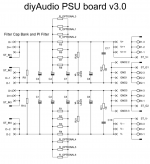
Block diagram:
This is my diagram of battery protection and charging: «power supply - power supply jack - Automatic Battery Charger – battery - Undervoltage-lockout – amplifier». So the first question: is it logical diagram? Is it right? Will it work? How will it work if my speakers are turned on, will the battery being charged, and will it take longer to charge?
If this block diagram is correct, than I can move further. And here’s the next question:
Question 2
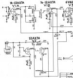
Battery charger and overcharging protection. As a charger, I want to use this scheme using L200C:
Resistor R2- R6 depends of the battery capacity (0.1C, so i chosen R4 - 0,75A). I want to add a relay, which is driven by transistor (I found this scheme in internet. Here it is:
Simplest SMF, Automotive Battery Charger Circuit Diagram Explained | Homemade Circuit Projects ). This addition must to turn off the further charging process if the battery is fully charged. So, please , look at this scheme, is it correct, will it work?
Question 3
Also, I presume, hysteresis is needed here for this situation: let’s imagine, that we connected the power source (I mean 220V socket and power supply) to the system, the charging started, meanwhile the speakers were working. When battery became fully charged (It’s important to say that we use cycle regime, so it’s around 14.5V), the system locked off the charger, but when the voltage became not 14,5 but 14, 4999 the charging process started again. Overcharge protection would turn off and on the charger many times - jittering would happen. That's why the system must turn on charger only at level of 13,5V (as example). This is hysteresis. So the question is HOW TO ADD HYSTERESIS HERE?
Question 4
I also made some findings, please to read and agree/disagree with me:
1) Battery work in cycle regime. Not in storage regime.
2) The cycle regime charging voltage - 14.5V
3) As soon as battery charged it must be locked off the load!
4) As a result of item 3, we need hysteresis
I’m sorry for mass of text, I was trying to write it shorter, but…) I also read a lot from boominator threads but still need to get information. I can’t use some turnkey solutions because of the cost. I hope answers would help other boombox makers)))