Unused pin 866A

Quick question(s). Can I use one of the unused socket pins on a 866A for a lug to extend my HV going to the top cap? Just 1 & 4 are for the filaments. 2 & 3 are unused so I was hoping to use one of those as a terminal. Related question is how far away from the surrounding metal structures would be a safe distance assuming a working voltage of 450V? Currently, I have about 0.1" or 2.6mm.

Another TC-750 question on mods...

I've been playing with a TC-750 preamp.

I found this guide on modding it: https://www.superbestaudiofriends.org/index.php?threads/tc-750-phono-pre-amp-continued.150/

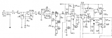
I've removed the 220pf input caps (circled in green in my included schematic), as I don't need any additional capacitance, I rely on whatever is provided by my cabling. I do have a couple of test records with pink noise, and I can confirm my response is very flat (+/- 1db) out to the limits of the album and my ADC (typically 20k).

In one of the comments, someone mentioned they removed the 1k input resistors (circled in red). I had tried this but thought I was getting more noise. As it turns out, my noise may have been induced by power/cabling issues. But, I did put them back in.

My Q before I try removing them again is, does anyone know what function they may provide, and whether removing them is indeed something that may reduce noise?

TIA for any help.

tc-750_mods.jpg

System two SYS-2322 digital input dead

So my Christmas present this year is the digital input of my system two 2322 dying with no prior notice.

During a routine self test it did not recognise any of the 3 possible inputs (BNC, XLR and Toslink) and threw "check connections" error. In normal instrument operation digital input voltage readout is always few millivolts. Only exception is BNC to BNC (cable loopback) when output is set to 2.5Vpp and Hi-Z the input readout is 2.9Vpp (?!), at 2.2Vpp output readout is 1.9Vpp and below 2.1Vpp output readout is always few millivolts. No more working (always few millivolts) if set to 75 ohm. The same with no cable connected an GenMon input or any other combination XLR and Toslink. It looks there is a kind of crosstalk because if I connect BNC to BNC and set input to XLR I still say valid data but voltage is, again, few millivolts. I probed the output of digital generator with an oscope and signal is OK.

So I am starting checking for any clue. I noticed on the digital connectors board there is a MAX310 multiplexer. Should I start replacing it? I know there are very competente users about AP old stuff. Like Audio1Man user. So it's great if someone could put me in the right direction.

Lack of schematics does not help for sure.

Thanks!

Building the 7pi (seven pi) speakers - Spring/Summer 2021

I wanted to upgrade my stereo system downstairs hoping to eliminate the effect which always reminded me where the sound was originating. My previous speakers were a pair of Sound Dynamics 300TI, which I like very much and worked very well in the room. However, I have a pair of BassZillas in my system upstairs, which create a huge sound stage. I was hoping for something similar downstairs despite the space constraints.

After researching for a while I decided to build a pair of Pi Speakers 7pi.
I have just finished building them and am delighted with the results. The 7pi creates a large sound stage, much bigger than the room where they are located.

Many thanks to Wayne Parham for sharing this great design.

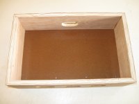
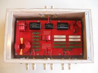
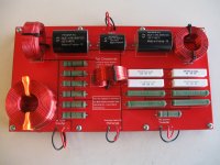
Here are some pictures of the build. I designed my own crossover PCB just as part of the enjoyment of building my own speaker system.

attachment.php


Also built a case for it.

attachment.php


Here is the crossover encased

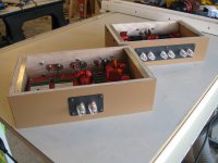
attachment.php


attachment.php


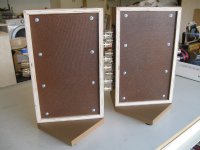
To fit behind the mid-horn I added a base to keep it vertical

attachment.php


attachment.php


attachment.php


This is how the crossover sits on the bass unit

attachment.php

Attachments

  • Crossover_assembled.jpg
    Crossover_assembled.jpg
    406.8 KB · Views: 1,434
  • Crossover_case.jpg
    Crossover_case.jpg
    346 KB · Views: 1,386
  • Crossover_encased.jpg
    Crossover_encased.jpg
    395.7 KB · Views: 1,402
  • Crossover_encased_side.jpg
    Crossover_encased_side.jpg
    341.6 KB · Views: 1,370
  • Crossover_with_base_top.jpg
    Crossover_with_base_top.jpg
    435.8 KB · Views: 1,382
  • Crossover_with_base_bottom.jpg
    Crossover_with_base_bottom.jpg
    515.9 KB · Views: 1,373
  • Crossover_with_base_and_lid.jpg
    Crossover_with_base_and_lid.jpg
    302 KB · Views: 1,363
  • Crossover_on_bass_unit.jpg
    Crossover_on_bass_unit.jpg
    229.7 KB · Views: 1,374

Source follower buffer/ccs implemention

Hi All,

Hoping for some advice with my current build. I am intending to implement a source follower buffer/bootstrap CCS for the input and driver stage, a bit like the below image.

Due to the heatsink configuration, I am limited to a about 2W dissipation in the FET, which means I can run it at 10mA or so.

I was hoping to run the 6SN7 at 10mA also (200V at 10mA looks like a real nice operating point under constant current conditions).

It occurs to me that perhaps the bootstrap won't work well supplying 10mA with only a 10mA sink capablity in the follower, i.e. the follower should possibly be run at significantly more current than the 6SN7. Is this a valid assumption? Not sure I completely understand all the factors at play.

I am pretty much locked in to 10mA in the follower, so the alternative is to run the 6SN7 at 5mA or so (with 20k load resistors).

Appreciate any thougthts you might have!

Greg


source follower.PNG

InDIYana 2022; "Missing Link" competition included....

InDIYana 2022 will be Friday May 6/Saturday May 7. Pertinent info at the website link, and is most concise as to needed information.
Information to be updated as it happens.

We are having a 'Voicing Day' In LaPorte on Jan 29th, see posted address on website.
We are minimal in RSVP at this point for Voicing Day. Just 6 of us. Please let us know if you are coming.
https://sites.google.com/site/indiyanaevent/
To Download measurement file for Missing Link competition/challenge, see event website or look here:
https://diy.midwestaudio.club/discussion/1769/indiyana-2022-missing-link-theme-announcement/p1
For those whom are international and want to be included in the challenge, please contact Mark at Meniscus.
Please register and let us know if you want to attend,
Wolf
  • Like
Reactions: indianajo

Replacements for SA1941 and SC5198

Hi All,

Repairing an Onkyo receiver. Shorted output transistors. Both an SA1941 and SC5198, which are obsolete. Interestingly, the schematics for the device list Sanken 2SA1695 and 2SC4468, which can be had. But some other threads have indicated to use Fairchild FJA4210OTU and FJA4310OTU. Anyone got any opinions on which? Price is comparable, the biggest diff is Digikey sells the Sanken's, and Mouser sells the Fairchild. Specs look similar enough.

Lovoltech LU1014 Power Jfet Group Buy

Group Buy signup sheet


With Zen Mod's recent news of the LuDEF amplifier concept, there has been renewed interest in the Lovoltech LU1014D power Jfet. Papa first used the LU1014D in the Zen Variations 8 & 9 and then in the First Watt F3.

Links-

First Watt F3

Zen Variation 8

Zen Variations 9

LuDEF

The LU1014D has long been out of stock and joined the list of power Jfets (SemiSouth R100) that we all want to buy and use but can't seem to find.

Luckily for us, a certain benefactor (initials are NP), has a stash of the LU1014D that he's agreed to make available to us through a group buy. A few members are working out the GB details currently- cost, shipping cost, sign up sheet, etc... and we expect to have the details on this thread shortly.

It will be an international group buy and we expect to have enough supply to fulfill demand.

If you haven't seen an LU1014D, I've attached a photo with an IRFP240 for comparison. They are tiny.

FAQ-

What can I build with the LU1014D? A- An F3, ZV8, ZV9, maybe a LuDEF. Schematics are all on line. Or maybe design your own amp.

Yeah, but there's no PCBs for those amps. A- True. Maybe we just need to sprinkle a few LU1014Ds around to get members to create a few gerber files. Seemed to work with the SemiSouth giveway. There's a few new Aleph J pcbs, plus renewed interest in the F1 and F2. Why not the F3?

Attachments

  • LU1014.jpg
    LU1014.jpg
    740.2 KB · Views: 2,896

Synergy attempt without compression driver

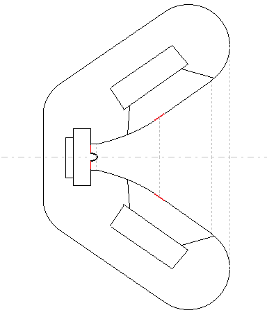
I've been intrigued by the Synergy concept for some years but have some resistance against using compression drivers. The very high sensitivity makes them noisy with my amplifiers. But primarily I've gotten really nice results with the ScanSpeak R2604 in a waveguide which makes me want to try it.

A first sketch:
530212d1455107911-synergy-attempt-without-compression-driver-r2604-synergy.png

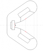
Inside. The woofers are Faital Pro 8FE200.

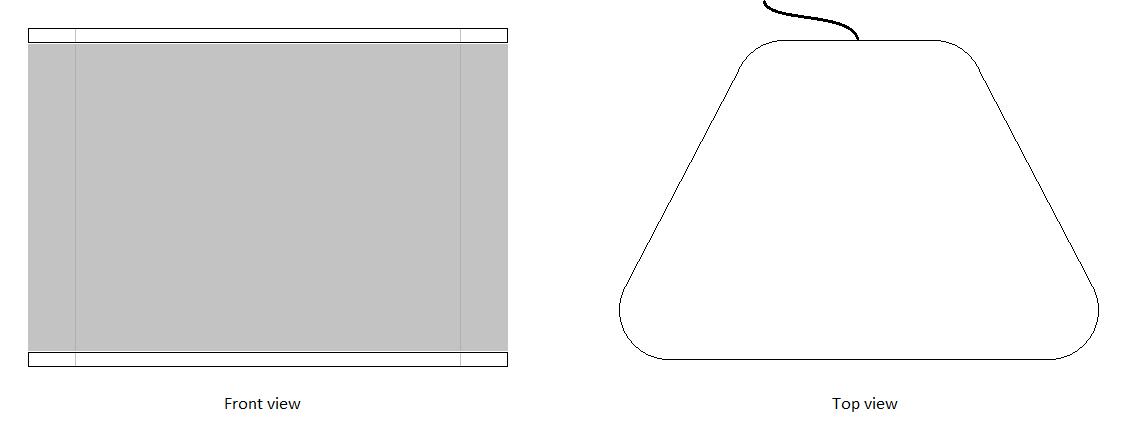
530213d1455107911-synergy-attempt-without-compression-driver-sketch2.png

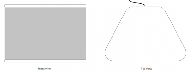
Outside view.

The size is about 50 x 35 x 30 cm (W x H x D, 20" x 13" x 12"), i.e. a quite compact synergy.

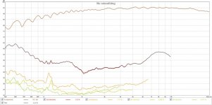
These are the horisontal polars of the R2604 in an early waveguide (210x130x85 mm):
An externally hosted image should be here but it was not working when we last tested it.


KpluznBl.jpg

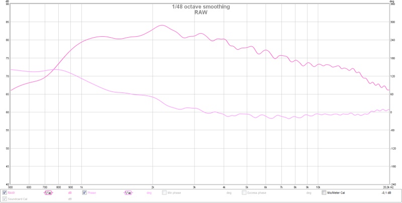
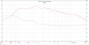
Measured waveguide (the brown one).

530214d1455108141-synergy-attempt-without-compression-driver-r2604-wg-raw.jpg

On axis, with phase.

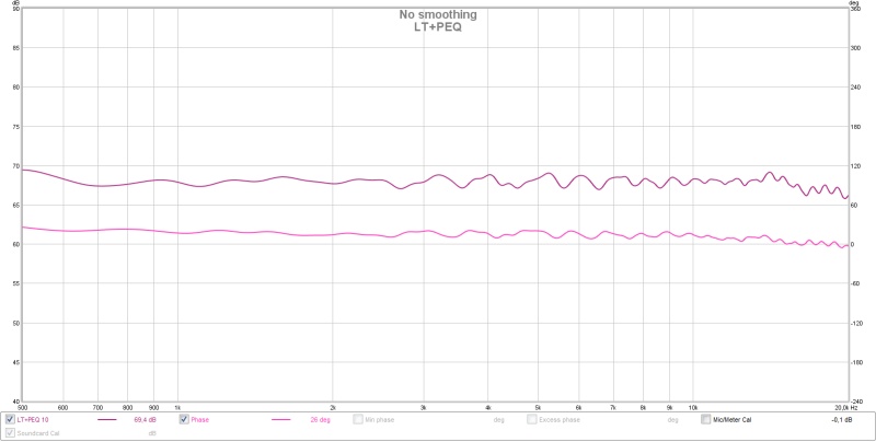
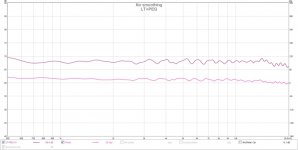
530215d1455108141-synergy-attempt-without-compression-driver-r2604-wg-lt-peq.jpg

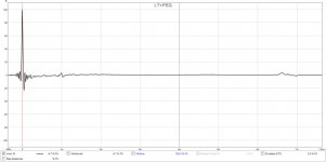
On axis with PEQ and LT.

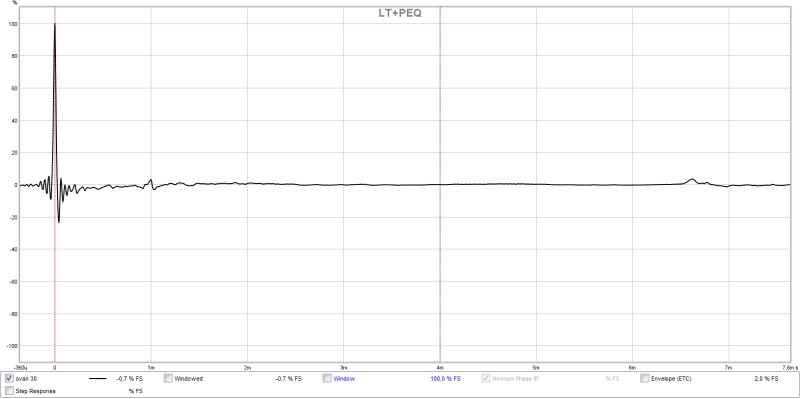
530219d1455108855-synergy-attempt-without-compression-driver-r2604-wg-lt-peq-impulse.jpg

On axis with PEQ and LT.

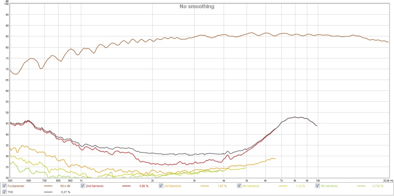
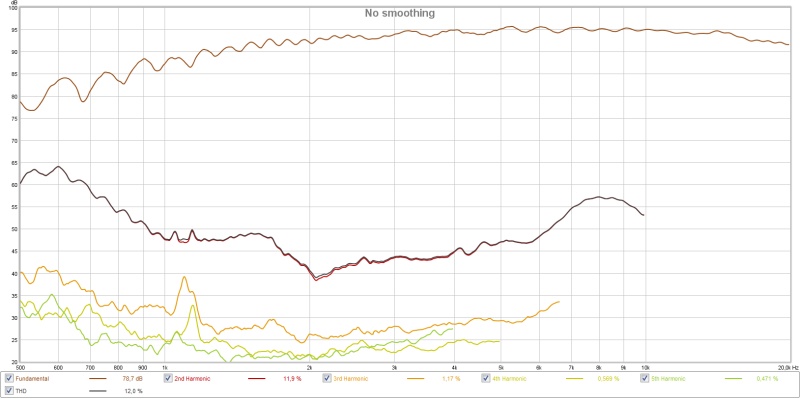
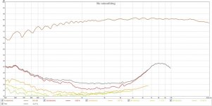
530216d1455108141-synergy-attempt-without-compression-driver-r2604-wg-dist-85db.jpg

Distortion at 85 dB with 1.2 kHz bessel (for Harsch XO).

530217d1455108141-synergy-attempt-without-compression-driver-r2604-wg-dist-94db.jpg

Distortion at 94 dB with 1.2 kHz bessel (for Harsch XO).The R2604 should be better loaded in the bottom end with a 50 cm wide waveguide (synergy horn) and that should reduce the distortion to enable a 1.2 kHz crossover and 95 dB maximum level.

The plan is to 3D-print the first part of the horn (throat) and then use wood for the last part.

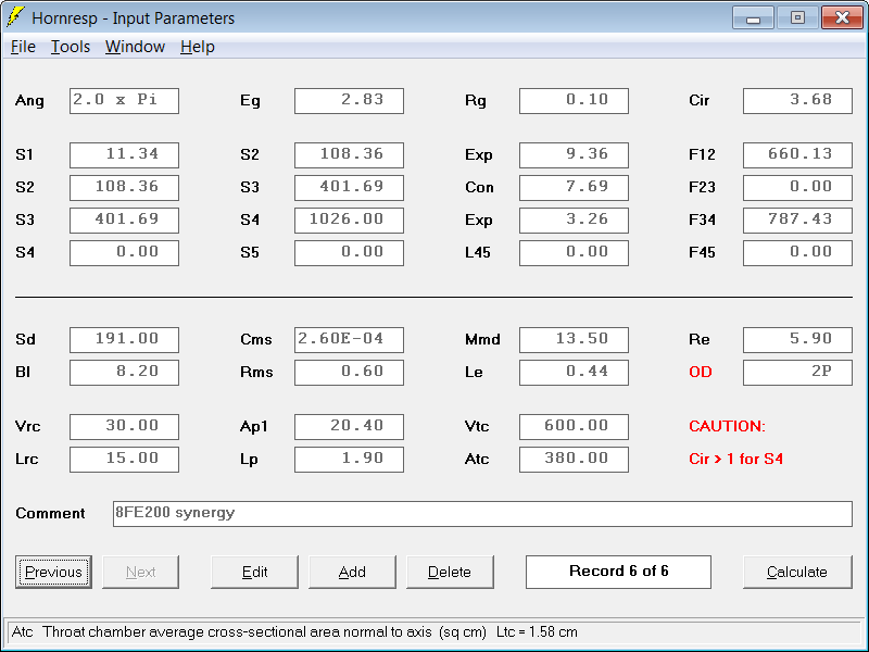
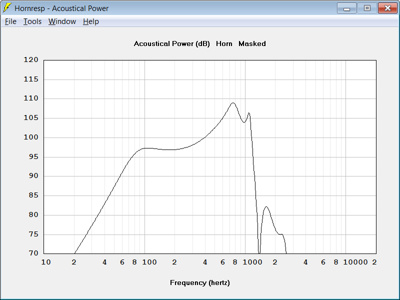
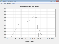
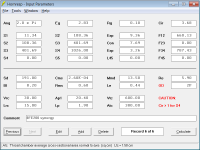
I'm quite new to Hornresp, but have tried a little:
530224d1455109880-synergy-attempt-without-compression-driver-hornresp-input.png


530223d1455109775-synergy-attempt-without-compression-driver-hornresp-power.png


Throat velocity (separate model) is 9 m/s at 2.83 V and diaphragm displacement is 1 mm. I've used 2 x 1" holes for each woofer in 19 mm MDF using minimal volume filler (measured the Vtc for the woofers at 350 ml).

The plan is also to have a leaky supercardioid setup for the woofers to stretch the directivity of the speaker down to below 200 Hz.

I'll post 3D-models later to show what I plan to print 🙂

/Anton

Attachments

  • r2604 synergy.png
    r2604 synergy.png
    6.3 KB · Views: 2,368
  • sketch2.png
    sketch2.png
    4.8 KB · Views: 2,315
  • R2604 WG raw.jpg
    R2604 WG raw.jpg
    52.1 KB · Views: 2,323
  • R2604 WG LT+PEQ.jpg
    R2604 WG LT+PEQ.jpg
    53.1 KB · Views: 2,252
  • R2604 WG dist 85dB.jpg
    R2604 WG dist 85dB.jpg
    72.6 KB · Views: 2,231
  • R2604 WG dist 94dB.jpg
    R2604 WG dist 94dB.jpg
    73.8 KB · Views: 2,299
  • R2604 WG LT+PEQ impulse.jpg
    R2604 WG LT+PEQ impulse.jpg
    48.1 KB · Views: 2,474
  • hornresp power.png
    hornresp power.png
    17.3 KB · Views: 2,229
  • hornresp input.png
    hornresp input.png
    20.6 KB · Views: 2,245

Finding the right amplifier for my 3-way speaker

Hello to everyone! I'm really new to the building of loudspeakers and I've decided to build a 3 - way speaker. I picked my drivers from Dayton:
Subwoofer: RSS210HF-4 8" Reference HF Subwoofer 4 Ohm RMS: 280 watts
Mid: PM180-8 6-1/2" Neo Wideband Midbass Driver RMS: 30 watts
Tweeter: ND25FA-4 1" Soft Dome Neodymium Tweeter 4 Ohm RMS 20 watts

I designed my crossover on vituix and I've attached my design.
微信图片_20220112172945.png
微信图片_20220112172958.png
微信图片_20220112173009.png
微信图片_20220112173015.png
微信图片_20220112173021.png
微信图片_20220112173026.png

My questions are
1. What exact amplifier should I get? I've read so many articles about this and was still unsure: Some say 2 x the subwoofer (which in my case = 560 watts) I am afraid that it might burn my tweeter. I've originally decided to use one amp to power all but if not possible, will two amps affect my crossover? If two amps are a better choice, which ones should I get and how should I connect them together?
2. I've noticed that the lower end of my impedance dropped to about 3.5 ohms, Is that a bad thing?
3. Is my SPL curve good enough? IF not please let me know which part needs to be improved!
4. If there's anything ridiculously wrong in the charts please let me know that as well!

Thank you all for your time!

Weird Kitty Hawk M1

A while back I bought a Kitty Hawk M1 amp.
However, I soon saw that this implementation deviated from the schematic that is circulating on the internet:
http://www.kittyhawkamps.com/schaltplaene/m1preamp.jpghttp://www.kittyhawkamps.com/schaltplaene/m1_m3_endstufe.jpg
What immediately strikes me is the combination of EL34 and 6L6 power tubes.
In addition, I did not have the switch to switch between EL34 and 6L6 and the Class A / AB switch on the front was also missing.
In short, time for reverse engineering.
Preamp.png

Poweramp.png

Power Supply.png


This does deviate from the M1 schematics that is circulating on the internet.
There also appears to be a tda2030 for the reverb.
The main thing that stands out is the power amplifier.
There seems to be a gain stage after the phase shifter. Has anyone seen this before?
As mentioned before, there are 2 types of power tubes in the power amplifier. Namely a pair of EL34 and a pair of 6L6.
Now these all have the same bias voltage and anode voltage. This doesn't seem right to me.
Then measurements were made on the power tubes. Below the result.

V7 - EL34
V8 - EL34
V9 - 6L6
V10 - 6L6

V7:
60W 81mA
120W 67mA

V8:
120W 68mA

Q9:
120W 52mA

V10:
60W 74mA
120W 67mA

Measurement on tube V9 deviates a lot from the rest.
Switched V9 and V10 for the test and did another test on the position of V10.

V10:
60W 60mA
120W 50mA

Doesn't seem like this tube is completely within spec?
And the rest of the currents, aren't they set very high?
For example, if I enter the data for an EL34 on this site: http://mail.robrobinette.com/Tube_Bias_Calculator.htm I could get about 38.9mA at 70% disipation.
This makes a significant difference.
In addition, the settings for both EL34 and 6L6 appear to be equal with the same bias voltage. This isn't quite right either, is it?

Weird ground loop?

I got a preamp that i designed. Its a single chassis dual mono, mixture of ground plane and star ground, completely seperate left and right channels except for the hum breaker nodes joined at chasiss.

I found a weird symptom recently. If i take the signal part of the rca jack (the tip) and touch the ground part of the preamp, that is one tip to the L ground and the other to the R ground, ill get a faint music irregard of the position of the volume pot. This doesnt happen if i touch just one tip to ground but if its to both channels theres sound. Which makes me think its a loop but in normal conditions the preamp is dead quiet. Infact its hum free enough to be a headphone amp for iem's.

Whats the mechanism behind why this might be happening?

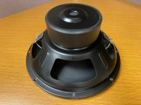
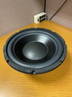
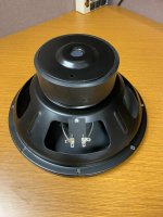
For Sale Adire Shiva Mkll 12in sub driver

Adire Shiva Mkll for sale. Dual 8 ohm coils. I believe it was purchased around 2005. I had many of these at one time. Always been my favorite for hi-end audio and theater. It was mounted in a box but never used. Send me a text if interested. I’m located in NY
Chris 631-553-7107
Price $150+ship

Attachments

  • 39B96180-34CF-4D32-A3C0-4389B98558D3.jpeg
    39B96180-34CF-4D32-A3C0-4389B98558D3.jpeg
    502.3 KB · Views: 97
  • 6A9E17CF-F67C-45F5-88B9-1608B224E777.jpeg
    6A9E17CF-F67C-45F5-88B9-1608B224E777.jpeg
    647.5 KB · Views: 97
  • EA242EB1-D8AA-4938-956E-6BB6F6868C63.jpeg
    EA242EB1-D8AA-4938-956E-6BB6F6868C63.jpeg
    512.7 KB · Views: 101

Finally found a good cheap 50mm driver

Testing out a 50mm dynamic headphone driver now and the initial results are very impressive. Most cheap 50mm drivers suck but this is the most neutral fullrange I've found on Ali so far. I've bought 4-5 drivers lately and this is the only one which is fullrange without beeing harsh. Its very detailed but not sibiliant. Bass doesn't go super deep but works for rock and most genres. Since its 16ohms it gives good dynamic and loudness from cheap bluetooth headset chip amps if they are rated for 16ohm. Put this driver into a cheap BT headset and I can assure you that you will be amazed over how much better it sounds. I think you can lower the treble with felt if you feel its too hot, or put a hole in felt backing if you want more bass from it. I haven't tried this since I think its perfect in its stock form 🙂 https://www.aliexpress.com/item/1005003441738083.html?spm=a2g0o.9042311.0.0.3ddd4c4doXfYRI

WTSwap - Matched Quad 2SK60/2SJ18s

I have a matched quad set comprising 2x 2SK60 and 2x SJ18s. These were purchased for a TA-4650 rebuild I am making, however they are -53 Ranking and I need -54 to -57 Ranking. Does anyone have an equivalent set with my desired ranking they would be willing to swap? Ideal would be -54 or -57, but -55/56 also fine.

The -53 Ranking may be used in TAN-8550 or possibly the TAN-5550 and the anticipate Nelson Pass VFET amp that is on its way to the DIYAudio Store.

All VFETS measure good with DMM.

This is SWAP only, not selling at this time.

I am located in Scotland, UK.

Jon

HV power supply board

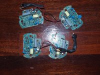
Hello, One of my KingSound King speaker has a very low treble output. The speaker has separate HV supply boards for Treble and Bass. Looks like i need to change the Treble HV power supply board. The existing HV power supply board works on 12v DC supplied from an external adapter. From my online research looks like it outputs 2.6Kv.
I've tried looking online but haven't found anything that i can retrofit, perhaps I'm not using the right keywords in my search? Can some point me in the right direction.

Here's the picture of them I found in another forum post on here.

Thanks.

Attachments

  • HVPS.jpg
    HVPS.jpg
    179 KB · Views: 156

any easy mod to eliminate turn-on pop?

I have Micca A250 digital amp connected with a 24 DCV ac adapter. I have it connected to an AC power strip with on/off switch. If I switch on the power strip followed by turning on the volume knob on the Micca the pop sound is minimal but if I forget and leave the volume knob on the Micca and switch on the power strip, it makes a loud popping sound. Is there a way to delay or attenuate the popping sound?

Effects of RC filtering on multiple aop feedback loops

Hi everybody,

First of all, sorry for the weird title but english is not my mother langage and besides I don't know how to describe it otherwise.
I'm trying to understand how this circuit works, especially the preamp. Could not find any answer to my question yet.

Let me explain :
I understand that the first half of the op-amp makes a bandpass filter, althought the values are quite strange for a bass preamp. My problem is about the path of the second feedback loop which puts in series C5//R5, C4, R4, R3//C3, R8 and C9.
In this case, how to know which frequencies are filtered at the output 1 of the op-amp ? If the second half was non-inverting, I would read two bandpass filter put in series, but here the second feedback loop is refered to ground through the first one... So the classic formula 1/(2piRC) can't work. Or am I wrong somewhere ?
Futhermore I read in Teemu Kyttala's Solid State Guitar Amplifiers (p210) that :

[R2] is extremely important in cases when the feedback loop’s connection to reference (or common) through [R8] is also capacitor coupled. [R2] (along with other parallel impedances) also sets the input impedance. To prevent the bias currents of the input from interfering with the offset voltage the value of [R2] should ideally be equal to parallel connection of [R8] and [R3].
(I changed the name of the resistor to fit this schematic)
This is not what I see neither. So what the heck ?

So if you have a clue of what is going on here or know where I could find an article or a bit of an explanation somewhere, I would be very grateful.

Cheers✌️

Attachments

  • Capture d’écran 2022-01-12 à 12.11.21.png
    Capture d’écran 2022-01-12 à 12.11.21.png
    123.3 KB · Views: 138

Audio Mkp capacitors in // with a driver ???

Hi,
In few kits or diy loudspeakers, people are using MKP and sometimes expensive audio MKP in // with the driver for their filter and damped by a resistor.
Does it make sense to use a low esr cap in such AC shunt arengement if at the end it sees a resistor ? What isn he benefice in spite of using a normal lythic non polar with lower ESR?

Is it snake oil or can it be heard VS a lythic non polar cap ?

What do you think or experienced ?

Weird question about TO3 and similar pucks: Air inside?

This question may seem awkward: what's inside a TO3 or similar metal-can puck? Do they contain air?

I am asking because colleagues at work are looking for old / archived air that could be analyzed for trace gases in order to reconstruct the trace-gas evolution of the atmosphere / air during the past few decades. Any insights or thoughts would be welcome.

Looking for a MC pre (10db) pcb that doesn't do the subsequent RIAA eq.

I have a preamp that has a nice phono stage, but is only for MM cartridges. I'd like to build a mc step-up unit that I can fit inside the preamp, there is space but it would be tight. Transformer or active is fine.

Almost all the designs I can find do the eq as well. I know haglabs used to sell the Piccolo, but no longer do. Kankd has a lundahl xformer kit, but looking for options to compare.

Spec scam?

Browsing for a tweeter for a new build. Notices many spec sheets stop at 20K, so their breakup behaviors are not shown. To me, this is almost a scam. A lie by not telling the full truth.
We can mitigate it some by use of a Zobel or more aggressive LP filter, but I still want to know what I might have to deal with.

Why does a 22K breakup matter? Harmonics, IM and resulting audible HD.

For Sale Various pro loudspeakers, amps, components, 19 inch gear

For sale:

4x modified cubo sub/21
-Lavoce SAN214.50
-18mm birch ply
-cnc cut
-dual baffle
-2 wheels
-m20 polemount
-6 handles
-Raptor liner coating
-custom metal connector panel
Price: 1200,- per piece.

2x 6th order bandpass
-B&C 15DS115-8
-18mm birch ply
-cnc cut
-4 wheels with brake
-m20 polemount
-2 handles
-Raptor liner coating
-custom metal connector panel
Price: 850,- per piece
Discount possible when multiple are bought and open to offers.

2x B&C F122AN (loaded with 12NW76 and DE800+ME90) 850,- for the pair.
1x Lavoce SAN215.30 (new in box) 450,-
4x Oberton 10MB300 (only used for testing) 400,- for the 4.
1x BMS 4550-16 (new) 80,-
1x P-audio PH220 (new) 20,-

3x Jedia JMA1410 mic/line mixer (nieuw >450,- ps) 125,- per piece
1x Dateq SPL2ts (nieuw >700,- ps) 150,-
1x Extron MPS 112
1x Jb Systems talen mixer/mengpaneel 80,-
1x Numark CDN77 USB Cd/usb speler (Nieuw >300,-) 175,-
1x Bosch PLM 4P125 (like new) Amplfiier equipped with DSP 500,-
4x Bosch LB20-PC90 8" installspeaker 500,- for all 4.

Located in the Netherlands (near Venlo/Eindhoven).
Shipping is possible, though I do not have much experience with shipping pallets. However, if there is a need for it, I am sure something can be worked out.

For more info please pm or a comment under thus thread 😉

Cerwin vega XLS 12s

I'm having a problem with the 12s, when it gets a LFE signal the sub starts but after 1-2 sec it starts to crackling and popping non stop.
Even if i remove the LFE cable it continues so it won't go to standby again, i have removed the standby PCB and reflowed it but no success.
Does anyone have a service manual or have experienced this before and fixed it?

/Daniel

Operating point for 6SN7

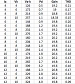
I am trying to figure out a good operating point for 6SN7. Morgan Jones says it is more linear at higher Ia. I tested my Tung-Sol 6SN7's with a common cathode circuit using Morgan Jones' best constant current source in the anode. I measured distortion with WinAudioMLS and a good sound card. The results are in the spreadsheet.
It looks to me like linearity is more dependent on increasing Va rather than Ia. Based on these results, I would pick an Ia=6-10ma, with at least 275-300V on the anode. This seems within the safe operating region.
Does anyone with more than my limited experience have any suggestions? Is the sound different at different operating points? Can this tube handle 3W at idle?
Thanks for your input.

Attachments

  • 6SN7spreadsheet.jpg
    6SN7spreadsheet.jpg
    139.9 KB · Views: 1,452

Physical widget to implement AutoEQ?

Hey all,

There is a fantastic compendium of parametric EQ settings for many models of headphones, in a github repository called "AutoEQ": GitHub - jaakkopasanen/AutoEq: Automatic headphone equalization from frequency responses

The typical route seems to be setting up a parametric EQ at the operating-system level, so that all audio gets routed through it. However, this is a bit of a pain and/or expensive, particularly when you have multiple computers / OS's.

I'd like to look at the possibility of using a DSP to make a physical widget which can implement the AutoEQ repository. I'm a newb when it comes to DSP, so any and all feedback / advice is welcome here.

(meta note: I wasn't sure if this belonged in the "headphones" or "digital source" subforum)

It looks like there is a relatively cheap set of DSP boards from WONDOM built around the Analog Devices ADAU1701: WONDOM | STORE

Does anyone have any experience or opinions with that DSP?

Any other DSP's or boards I should look at? How would you approach this project?

Searching for a multichannel dac DIY solution

Hello
like the title says i search for a diy solution of a nice dac (that maybe even outperforms my current modded topping d10)
i came across this site https://www.diyinhk.com and the dac solution (seperate output stage + dual mono xmos board, tho im unsure if it supports 4 i2s channels) ian has
i need 6 or 8 channels, i know there is this motu interface which seems quite but nice but i wanted to ask if there is a good DIY solution, that i can maybe even mod myself a little bit, it should be fairly plug and play tho (but soldering is no problem)
i dont mind paying a little more in the end since i could upgrade as i go (add more stereo dacs since 4 i2s are possible and just transfer stereo anyway), specially if it would outperform the motu

i would need this to go full active in the future with moode(rpi) and camilladsp

SONOS-DIY Kitchen Stereo System

Hi

For inspiration...

For many years we had a Squeezebox Radio for daily listening in our kitchen.
It was one of the first internet radios and works perfect but over time it becomes a little unstable and I was searching the market for an upgrade.
Must of the alternative for better sound quality was wifi speakers using AirPlay but then there was the SONOS systems but more and more I was searching the more I could see that no ones where using really hifi drivers.

So it was clear that I had to go the DIY way – Absolute no problem in that I like to DIY!
Short story and this was what I ended up with:

2 x IKEA Symfonisk
1 x IKEA remote
2 x SB29RDAC-C000-4/Fabric
2 x SB15NRXC30-4

And cabinets to housing the stuff.

First I had to see what was going on in the IKEA speakers.
Measurements:
PC – REW – TuneBlade to the Speakers

The two IKEA drivers connected to my test amp:
1.jpg


The Ikea drivers and the SONOS amp:
2.jpg


Conclusion:
The Tweeter sensitivity is about 7dB more efficiently than the woofer.
Crossover: 1.400 hz.
Electric LP slope: 24dB octave
Electric HP slope: 12dB octave
Acoustic both: 24dB L/R
Info on the WWW: 2x35W

In stock I had these drivers:
2 x SB15NRXC30-4
2 x Vifa XT25SC90-04
2 x B&G Neo3 planar

3.jpg


It was clear that none of these tweeters could go down to 1.400 hz so I had to find some new.

The SB29RDAC-C000-4/Fabric is very inexpensive and perfect in this setup!
I must say that SB Acoustics drivers are my favourites – they are well made and very reliably!

Measure the new drivers in cabinet – 50 cm:
Woofer + Tweeter + SONOS amp
4.jpg


Complete with and without TruePlay:
5.jpg


The box size is only 3L so too little to get any bas out of that but the TruePlay eq that and it works!
TruePlay Teck
Look at the Blue graph: 40-20.000 hz!
Did I tell you that the sound quality is on the next level for a kitchen system😊

In my Hi-fi setup I have a Lyngdorf TDAI3400 and are familary with RoomPerfect room correction not saying that SONOS TruePlay is on that level but here in this price level it is awesome!

Pictures - Pictures tells more than words…
Unmounting the SONOS amp from the IKEA Symfonisk.
This board is exactly the same as the one in SONOS ONE - Maybe difference DSP settings. No Ikea label on it only SONOS.

6.jpg


7.jpg


8.jpg


The new amp cabinet – made of bamboo also from IKEA - 2 x Monoblocks🤗
9.jpg


10.jpg


11.jpg


12.jpg


The new speaker enclosure made of solid oak + MDF.
Size: 360x240x100 mm.
13.jpg


14.jpg


15.jpg


18.jpg


19.jpg


20.jpg


21.jpg


And the left one is on its way...

Stephens Trusonic tweeter and crossover advice.

Hey all.
I recently inherited a set of stephens trusonic speakers. 15" woofer, 8" full range, and a trusonic 5kt toroidal tweeter. The cabinets were compromised so need to be rebuilt.

The woofers are in general good condition. One 15" has a slight noise with 40-60hz sine wave but it's unotticed with music so far.
The 80fr seem to be in great condition.

One of the tweeters is gone completely.

I'll post pictures soon.

I'm going to rebuild the cabinets in a 3 way configuration.

I'd like to do an econowave tweeter project to replace the tweeters and am wading through the impressive threads on that. If anyone has a direct line to an econowave project with 2khz+ crossover point, id appreciate a link.

Im looking for info on how to extract the theile-small parameters from the woofers in order to make crossovers for them.

Or

If there are some designs for trusonic woofers around, that would be a great place to start.

Thanks.

stand free or in wall?

As we are DIY, we have more choices. I suspect many of us woudl not be afraid to cut a hole in the wall and can build boxes in unconventional shapes.
So, my thoughts are such. For ultimate performance, is in-wall actually a better design? Moves the edges out way further, No 2 foot surfaces to mess up imaging. Of course, many rooms would not be suitable.

I was at my sisters where their HT has the three fronts in-wall with pretty decent plates. Imaging was very good and the top end needed less eq for raggedness. In many rooms, this would allow the speakers not to dominate the architecture. In a HT, not that big a deal but for us who listen in a living room and also live in them. Not good for the ego "mine is bigger or more expensive" market of course. Does not work for Maggies. I have not heard things like the B&G ( gone sob sob) or the Martin Logans in wall.

Any experiences? What may I be overlooking?

Another question I was wondering about is how far away can we get away with a tweeter from the mid? I have a difficult HT arrangement requiring L&R to be at the ceiling. Center brings down the voices mostly, but still image can jump around. I could move the tweeters down a foot leaving the mids up where there is physically room.

Multispeaker headphone?

I was told to post here so please be gentle, I'm a noobie 🙂

I'm in search of holographic 3d like soundstage and when i came across quadraphonic headphones that's exactly what I wanted to do! I ordered an old vintage toshiba quadraphonic phone. I tried to find the sizing of the drivers so I could order new ones but I guess I'll have to wait.

I am going to be making new shells for them since I can't tear apart the great looking stock pieces. I was going to do 2 50mm 32ohm drivers on each side and was wondering if I needed to get any special components to get this done.

Just so you know I am trying to build FUN headphones just to see what happens. I have nothing to do and this seems like a great hobby for me. I already have my other headphones for what I need...but now I want to just build something outrageous for indoor use. Its main use will be for gaming or listening to them on my bed with music or movies.

So I have a few basic questions:

1. They come with 2 6.5mm plugs for the front and rear. I know they make dual 6.5mm plugs that come out to a single 6.5mm plug, could I still that with my XDUOO XD05 that accepts 6.5mm connections? I understand that the sound might be in mono, but would it work or is the electrical system in them totally different.

2. What size wiring should I get for the headphone speakers?

3. Are there any passive components I can add in to change the sound of the speakers? I know this is done at the amp level with tubes or whatever amp you choose.

And yes, I am crazy.

MOSFET replacement queston. K135 and J50 with BUZ900/BUZ905 vs BUZ901/BUZ906?

MOSFET replacement queston. K135 and J50 with BUZ900/BUZ905 vs BUZ901/BUZ906

Hi all,
I have some noise issues in my amp and I would like to replace the mosfets. I already have a thread running about the amp here but I want to know what are my options for the MOSFETS.

I have already dug around but I want to make sure there is not something I am missing.

The originals are: K135 and J50 MOSFETS

People recommend:
BUZ900 & BUZ905 as the exact replacements at $10 each ;( for $120 total from Newark

or I found the

BUZ901 & BUZ906 as alternative replacements at $8 each
frown.gif
for $96 total from Newark

I also found the BUZ900 & BUZ905 on eBay from a Chinese seller for $5 each
BUZ900 Manu IR Encapsulation TO 3 N Channel Power Mosfet | eBay

BUZ905 Manu IR Encapsulation TO 3 NEW Product Under Development | eBay


The parts from China will cost me about $70 with shipping but will take forever to come and I am not sure if they are legit :/


I compared the specs on the BUZ900/BUZ905 vs BUZ901/BUZ906 and the only difference is the Vds respectively being 160V,-160V and 200V,-200V. The Hitachi MOSFETs are rated at Vds 160V and -160V. They also share the same datasheets!

For me it is a clear choise to go with the cheaper and better Vds MOSFET set of BUZ901, BUZ906. What do you guys think? Is it going to screw things up?

Thanks!

Aviation Driver replacement

I have a set of DCs (David Clark's) that are my daily driver for work reasons, lol. Other than that I run HD650s. I've been interested in upgrading the drivers on the DCs but they have a weird diameter (71.5mm) and are 19 ohm.

My question is, has anyone come across and upgrade to these? Additionally, I've flirted with the idea up doing and IEM on one side.

Any input would be very much appreciated!

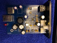
ES9018K2M usb DAC TOSLINK extension - i2c problems

Hello to all. I am new to this forum and this is my first post.

I have started DIY project of extension my old USB sound card DAC with optical audio input (TOSLINK). The usb DAC is based on SA9023 which is connected to ES0918K2M over I2S interface. Idea is to extend the board with Toslink reciever and connect it to ES9018K2M SPDIF input.
IMG_3536.jpg IMG_3537.jpg
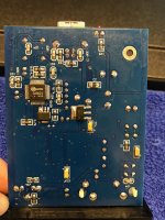
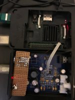
First step was to add Toslink receiver and connect its output to ES9018K2M GPIO2 as SPDIF input, after that plan was to use ES9018K2M GPIO1 as I2S\SPDIF input selector switch. To make that work ES9018K2M registers needs to be configured properly over I2C interface. I used raspberry Pi 3 Model B+ to establish I2C communication with ES9018K2M but was not able to detect the chip address 0x48:
pi@raspberrypi:~ $ i2cdetect -y 1
0 1 2 3 4 5 6 7 8 9 a b c d e f
00: -- -- -- -- -- -- -- --
10: -- -- -- -- -- -- -- -- -- -- -- -- -- -- -- --
20: -- -- -- -- -- -- -- -- -- -- -- -- -- -- -- --
30: -- -- -- -- -- -- -- -- -- -- -- -- -- -- -- --
40: -- -- -- -- -- -- -- -- -- -- -- -- -- -- -- --
50: -- -- -- -- -- -- -- -- -- -- -- -- -- -- -- --
60: -- -- -- -- -- -- -- -- -- -- -- -- -- -- -- --
70: -- -- -- -- -- -- -- --


IMG_3635.jpg

As it can be seen form picture above, SDA and SCL lines are pulled up by 4k7 resistors, cable to RPi3 is short and connected to corresponding GPIOs. I2C is enabled in rpi3 config and baud rate set to 100kHz. USB DAC board is powered from rpi3 via USB cable and works properly. Later, I removed 33 ohm resistors from I2S lines to disconnect SA9023 from ES9018K2M and exclude possible interference, but that didn't fix I2C communication problem.

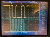
My next step was to connect oscilloscope and check I2C signals when sending command:
pi@raspberrypi:~ $ i2cget -y 1 0x48
Error: Read failed


IMG_3634.jpg

Form picture above it is evident that for some, to me unknown reason, ES9018K2M doesn't put ACK signal to low.
Any help, or suggestion how to fix the issue is appreciated.

Upgrade my LP12 or move on?

Hi all, first post on the forum. Joined a month ago and have been enjoying reading many posts; fascinating stuff!


I have owned a Linn LP12 a few years and did a few repairs and upgrades earlier this year - Cirkus bearing, Armageddon clone, Rega RB202 and a DIY aluminium subchassis. It sounds good but Im not entirely happy with it; so the quest for upgrades continues. The next step was to change the tonearm and make another (mk2) subchassis.


The new tonearm is an Audiomods series 6. It arrived in the post today and looks great!


Reason for this post is to check with guys with more experience whether I am better at this stage pausing and switching to another platform and move on from the LP12. Im trying to get to a point where I have a very good TT I can settle down with and enjoy. Can I get better results with a different unit, for similar cost and effort? I had not heard of Lenko before joining this forum but see that gets good reviews. Is it worth moving on to a GL75 or some other option? I don't want to spend thousands, so a very good new TT is not an option. Also the Mrs likes the retro look (its the only aspect of my hifi she likes!).


It would be good to get some suggestions so I can research further. Im ok spending time and effort upgrading an older unit diy. I have a woodworking workshop and a metal lathe too. Regards, Mark.

HP Agilent 35670A UK4 option

Hi I have a fully optioned 35670A ( 4Ch ) with Basic and operating on a Agilent IEEE488.2 -Lan Network.
I was would like to get the UK4 hardware option but I am stuck for the 7 Pin LEMO microphone.
Opt is 28v or 200v microphone system.
Suggestions in type of mike or amp is required. Also LEMO 7 pin - where do you get a suitable UK4 - LEMP plug?
//Regards nick

Insulation requirements for power transformers (international, CE)?

Or more specifically in terms of breakdown voltage. I participated on CE testing once, but unable to find internet info about the testing protocol being executed. These could be helpful?

If memory serves me right, one of the test consisted of applying High voltage High frequency AC voltage capacitive stressing of the primary to secondary dielectric for a fixed period of time.

P.S. I found these and these as a good start
https://www.st.com/content/ccc/reso...ons/en.Wurth_Design_Considerations_Munich.pdf
https://www.digikey.com/en/articles...-should-be-considered-in-a-transformer-design

Buying Advice Class D amplifier board - no hiss & no "plop"

Dear community,

I am in search of a good Class D amplifier board with small measurements fulfilling the following criteria:

- 24V operating voltage
- no hissing (no high gain required)
- no "pop" sound on turning on the amplifier
- preferably mono design or stereo design (no seperate subwoofer channel etc.)
- preferably small size

I bought 4 of the TDA3116 100w mono boards (XH-M542) and was very disapponited. The board has a lot of hissing and the speakers pop when turning on the amplifier. Modications are not possible because the heatsink is glued to the TDA3116 and cannot be removed without ripping the chip off.

Thank you very much for your help.

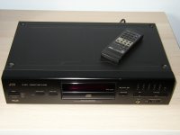
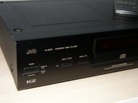
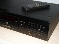
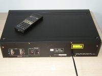
JVC XL-Z674 K2 interface CD player with remote

Hi All,


I have for sale a JVC XL-Z674 K2 interface CD player with remote control unit.
It's an excellent sounding machine. Cosmetically it's overall pretty good, but has some marks here and there. (Please see photos)
It's tested and working fine. ( It's 240V UK model but is also be fine on 230V. )
These don't come up too often, and give a superb sound quality largely due to the K2 processing.
I'm asking GBP85 for it + GBP12 (UK delivery) - for European countries I can quote (around GBP25 to most places like France or Germany)

Please send a PM if you'd like it.

Bank transfer or Paypal friends for payment.

Cheers,
Rob

Attachments

  • jvc 674.JPG
    jvc 674.JPG
    588 KB · Views: 489
  • jvc 674 cl1.JPG
    jvc 674 cl1.JPG
    574.5 KB · Views: 410
  • jvc 674 cl2.JPG
    jvc 674 cl2.JPG
    646.5 KB · Views: 442
  • jvc 674 rear.JPG
    jvc 674 rear.JPG
    651 KB · Views: 571

Best filler for speaker stands?

I can't find anything particularly interesting or original on what to fill speaker stands with. Just the usual lead (toxic, advice is don't use it) and sand. In addition there's Atabites for Atacama stands - tiny shards of steel sold in bags.
http://www.atacama-audio.co.uk/p/atabites-smd-z-7hd-inert-filler
So what about various tiny pieces of metal like screws, nuts etc? Anything that can be bought cheap in quantities?

And how about stone dust which I've seen mentioned? That's available from builders merchants.
https://www.wickes.co.uk/Dansand-No-Weed-Block-Paving-Sand-Stone-Dust---20kg/p/131899
Any bright ideas for something cheap and a heavier alternative to sand?

Looking for some interesting discussion here, including what's the optimum level for filler - 1/3, half, 2/3 etc.?

A BA-1 FE as preamplfier build thread

There are plenty of threads on the burning amps, but none on just the BA-1 FE as a stand alone preamp that I was able to locate. Starting this in the hopes it is needed....if not, ohhhh welllll 🙂

I have spare Antek AS-1220 and AS-1228 transformers, as well as multiple unbuilt Salas BiB kits and a few original peter daniel PS boards.

Here's my questions, to start:

Lightly ( LM317 ) regulated or shunt regulated power supply? ( I haven't built a shunt regulated PS yet )

How much gain will the BA-1FE make?

Can the BA-1 FE gain be easily adjusted?

Would a certain value of volume pot would be preferred? I have alps blue velvet 20K and 100K on hand already.

If this thread doesn't get deleted I fully intend to use it to ask a large amount of stupid questions that other people will greatly benefit from.

😀

LX-Mini + 6-24 Crossover

I built a normal Pass 6-24 crossover and I was impressed with the results vs a passive crossover on the same speaker. I was also interested in the Linkwitz builds and his collaboration with Mr. Pass. I took the plunge and constructed a pair of LX-Minis. Initially I used a MiniDSP HD for correction and was pretty impressed. But already sold on the ACN solution, I wanted to compare to the ACN Nelson constructed for SL for the Mini. LX-Mini XO I built it and it was a huge improvement over the DSP.

I wasn't impressed with the low end on the Minis so I decided to construct another 6-24 to cross from the Mini ACN to a woofer/sub woofer low level output. I internally fed low output from the Mini ACN to the input of the 6-24 ACN board. This allows me to characterize the High Pass curve on the Mini mid-range speaker and the low pass curve to an additional sub-woofer output. Effectively making this a very characterizable three way Mini crossover. It is working extremely well. Thought I'd pass this idea along.

ACtC-3fwuhCWXumNbsJXkUv64zRENuVGSdD9Sv5nrB3cbUJiWVlrh5KTw3MIhJkKqBrOEci77eQO5GUThqH8d5Uxm4BsfMBDp1zz972McRm8NaYyh8wqeRXGpmDug_JlWNUl2RzoE4tnt9MOjzAMWAPq_-_B=w1199-h899-no

An externally hosted image should be here but it was not working when we last tested it.

Does a Gedon power supply have to use a toroidal ?

hello. Im thinking of building a Geddon power supply for my LP12. In the garage I have a old 1000v/a 240v to 110v step down transformer. Its definatley not an auto transformer, it is a old style transformer rather than a torroid. Can i use this ARLEC 240v to 110v step down transformer for a geddon or does it have to be a torroid? thanks

Driver for dual 12" sealed

I'm in the planning stage for a pair of subs to go with my upcoming DIYSG Vortex-15s. Due to the size of the Vortex I'm constrained to a pair of 14.5" wide cabinets and 12" drivers. Power will be a Crown XLS2500 already on hand, with MiniDSP 2x4 for processing and room correction. Based on this I was looking at doing dual sealed 12s, in 60-90 litres and applying Linkwitz Transform. The ability to dial in any f3 and Q appeals to me since I'm not sure what is going to work best in-room. Usage will be both music and HT, but the subs are mostly to cover the 20-40Hz range for movies.

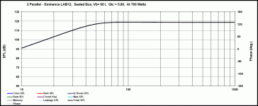
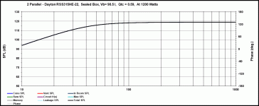
The question I have is around drivers. I think I've narrowed it down to either the Lab-12 or the new RSS315HE-22. A parallel pair of either provides a load 2 ohms or greater across the sub range. The Labs hit xmax at about 700W input in 60L, so the amp would need to be backed off a bit. The RSS pair can take all of the power but wanted a larger box, with 90L being about as big as I can go, and they still have excursion to spare. Surprising to me, the RSS only model a couple dB higher. The main advantage of the Labs is that the box is small enough that I can go dual opposed. With the RSS both drivers would need to be front-firing, and I'm worried that even a well braced box is going to shake from the driver movement.

Graph3 - 60L at xmax.gif

2xLab-12 pros:
- smaller box allows dual-opposed
- more sensitive ~103 dB at 20 Hz on 700W
- about $150 CAD lower cost for 4 and available locally
Lab 12 cons:
- xmax and thermally limited, not using full output of amp
- older design (although highly regarded)

Graph1.gif

2xRSS315HE pros:
- slightly more output ~105dB at 20 Hz on 1200W
- amp limited, excursion and thermal ratings exceed amplifier capability
- double spiders & lower distortion motor?
RSS315HE cons:
- larger box to get more out of the drivers precludes going dual opposed
- only 2 dB more output for nearly double power
- higher cost

Right now I'm leaning towards the Lab-12, based on lower cost, smaller box, and very similar output using less power. Are there other drivers I should be considering that might be better suited to this application?

New Reference Speakers with Full/Wide-Range Driver

Good day to all,

I am just starting to design my next pair of reference speakers. I have been through the many designs and styles, 2 ways, 3 ways, 4 ways, sealed, bass reflex, transmission line, and more, so I have a good idea what I expect and want from a pair of speakers.

My latest and most intriguing experiment has been full-range drivers. I am converted to the concept as flawed as it is, I had just grown tired of listening to crossovers messing up my jazz and vocals. As I have been listening to a lot of acapella music lately, you can always hear a crossover smear somewhere in the vocals. It is just too good to be able to listen to a sax run up the scale and it is smooth as silk or listen to an acapella quartet without the crossover humps or dips.

But(it is always there!) I am finding that the ends of the spectrum just put to much pressure on any single driver that I have heard, you give up good deep bass, and find the highs can be just a little too gritty for my ears.

So to remedy that, here is what I am proposing to do.

A woofer in a transmission line with a full/wide-range driver as the mid-range covering from 90Hz+- to 4,000 - 6,000Hz area where a tweeter or super tweeter will take over. Essentially a three way.

Lets look at each driver and what we want from it and why.

The woofer could be a 10" or 12" Peerless or Scan-speak, with a folded transmission line tuned to a bass cutoff of 30Hz or preferably less. I do not want tubby, fat, or boomy bass, I want clean, quick, fast bass, I will using this for music only. It would need to carry the bass up to around 90Hz and I want to use as simple of a crossover as possible, preferably first order.

The mid range - I want the full vocal range completely free of cross-overs, hence the low 90Hz, I have sang with good bass singers that can smash a C two octaves below middle C, which is only 65Hz, not many but a few. most of the vocal range is from A3 - 87Hz through C6 - 1,050Hz, with a select few sopranos shattering glass a few notes above that. A piano tops out at about 4,200Hz or so, above that you have mostly second harmonics happening. So by covering the 90Hz though 4,000Hz with one driver we completely eliminate all crossovers in the critical hearing, vocal and fundamental range of most instruments. I am completely annoyed with beaming that goes with most larger wide-range drivers, the largest driver I would want would be 4" preferably less. So here is my shortlist of drivers, the Jordan JX92S, Bandor 50AFSW/8, which are fine except are not very efficient. I am open to any suggestions you may have on suitable drivers. I would go for a Manger, but that is such a quick driver that mating a suitable woofer is almost impossible I am told. Again I want to keep crossover as simple as possible, and if possible use enclosure construction to work as passive crossovers. With the two above drivers, a high pass filter is unnecessary because of the roll-off of the drivers. Most likely a low-pass would be unncessary also because we could just tweak the high-pass on the tweeter to pick-up where the mid-range is starting to tire.

Tweeter - 4,000-6,000Hz and above . I have not given much thought to a driver here and would love to hear you recommendations, again remember I have no love for beaming or narrow sweet spots, I prefer a wide, full listening area. So I am assuming a 3/4" tweeter or maybe even a ribbon would be what we need.

I am hoping for a passive cross-over consisting of a first-order low-pass for the woofer, and a first-order high-pass for the tweeter. I may decide to pinch off the top of the midrange just to avoid too much glare and muddiness because of expecting to much of the mid-range in complex and difficult passges. Plus some possible pads to bring everything into line.

OK, fellow full-range junkies, let's hear your ideas and criticisms. I know there are some very experienced full/wide-range listeners in this forum including Planet10 aka Dave(with some very interesting driver ideas), Dice45 aka Bernhard, Mohan Varkey, just to name a few. A budget is not really an issue here, except like everyone, I am always interested in spending less instead of more.

Cheers,

Surf, Sun & Sound
Scheduled for resolution UX improvements

Hi;
I'd like to post about some UX improvements that could be made in CSS.


  • These buttons aren't lined up 🙁
    1639745655977.png

  • Certain buttons/actions lack feedback:
    • "Okay" button is grey, whether or not you have chosen an avatar or not. It's usual for this button to turn 'active' when the action is available (after uploading.)
    • There is no hover feedback on Okay
    • There is no hover feedback on Delete for the purpose of warning a user they are performing a destructive action.
  • The Paid Member icon seems a pixel too small for the star to center properly (this is a lower-dpi or lower-zoom related issue.)
    1639745862660.png
  • The Paid Member icon could use a text feedback/marker. I did not know what this icon was until I opened the debug console.
    In the below code, I found that the user banner text (which is in bold/strong html5 tags) is hidden by virtue of setting the font size to 0, inherited from the parent container that holds both the icon and the text (<em class="userBanner diy_paidUser">.)
    HTML:
    <em class="userBanner diy_paidUser">    <span class="userBanner-before"></span>
        <strong>Paid Member</strong>
        <span class="userBanner-after"></span>
    </em>
    CSS:
    .userBanner strong {
        font-weight: inherit;
    }
    
    .diy_paidUser {
        font-size: 0;
    }
  • The icons on the side bar under a user could use some improvement in consistency. As with precious display, the UserBanner that shows paidUser has a tag (in <strong>), but hidden. The OP/Original Poster tag does not; but it's also styled and sized differently, leading me to believe it might be simply an oversight 🙂.
    1639747337556.png
  • Some more cut off text :s
    1639747978799.png
  • Hovering here does not turn the text white to contrast it with the purple - or it's not supposed to turn purple
    1639748058281.png

  • This icon has done a disappearance trick.
    1639748186576.png

How do I make a Linux/ALSA loudspeaker crossover DSP?

Hello everyone!

I was wondering if it was possible to take a stereo signal from, say, the line input of the computer, route it through LADSPA plugins that would control the filtering and delay of the signal, and then output it to the physical outputs of the sound device.
I recently accomplished this using JACK in this thread, and while it was quick and easy to do, I've found that asound.conf has always eluded me, and wanted a lower-level challenge 🙂
I have seen that there are a number of threads here that document how this work is done when chained to a music player's output, but I would like to do the same with the live input, if possible, without the need for an application.

So, to recap, is it possible to:

  • Receive the stereo signal from the line input
  • Split the signal into 3 stereo pairs
  • For the first pair, use a low pass filter for Bass
  • For the second pair, use a bandpass filter for Mid
  • For the third pair, use a high pass filter for Treble
  • Output each pair to a different output (I'm only using one audio device)

Thanks for the help!

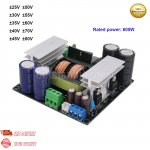
600W LLC Power Amplifier Switching Power Supply .... not giving the correct secondary voltages!

Have bought one of these SMPS on eBay:

https://www.ebay.com/itm/154164805607?hash=item23e4f03fe7:g:uzgAAOSwlxRfVvpt
I actually also have one running +-70V and a new one for +-35V, all for supplying class d amps.

The +-70V one did work and is running in my main amp right now. I checked the additional supply voltages, and was a bit surprised they where a bit off, not delivering +-12V or +12V, as I recall they where a bit higher, but thought this was down to these to being regulated, and as I'm regulating the +-12V down to +-6V on the amp board, and as the +12V which I referenced to the -70V for supplying the Gate driver, it all worked fine.

But with the +-35V supply, I'm getting only +-6V and +6V!!!!!

Anyone have the same experience with these SMPS?

I'm wondering if the transformer is the same for all the different output voltages you can chose from?? Or whether this is a fault altogether.

As the output is not regulated you'll need more windings for getting 12V on the +-35V SMPS, than for the one giving +-70V!
There is a small resistor on the bottom side of the pcb, and I'm wondering if this is actually how they change the main output voltage, and that this is not done using different transformers!

Attachments

  • s-l1600.jpg
    s-l1600.jpg
    232.6 KB · Views: 266

MOSFET amplifier : NMOS Quasi output stage

I have previously designed BJT complimentary output stage based
amplifier. It is first time i am going to do a mosfet Class AB amplifier.
I want it to be Quasi Complimentary NMOS output stage, preferably IRFP240
as Models are easily available
How to protect mosfets from blowing up due to oscillation as the
amplifier will work up to 300Khz?

Design Target:
*2W class A region before moving to AB
*300Khz Bandwidth
*At least 100V/us Slew-rate
*Low phase shift [ Less than 6degree]


Ripple eater are taken from Wolverine Amplifier

Please help me to setup spice to find out THD, and output stage.
How to measure slew rate and check out phase margin under Lt-spice?

Preliminary Input and VAS stage , i have attached

Edit: Removed *Low Phase Margin [Preferably Under 6d]

Attachments

Any new Tube Charts for NRI Model 70 Tube Tester?

Hi all,

I have recently acquired and completely restored and calibrated old NRI Model 70 Tube Tester.

It works perfectly, but I miss a lot of tubes in my chat (on build-in roll).

Mine roll is indexed as NRI-70 3-53," (assuming from 1953) and the previous tester's owner included another Tube Chart Roll, indexed NRI-70 3-59" (assuming from 1959).

I know it's old model, but the latest data I found was in NRI Journal from 1962, stating the latest Tube Chart of the time is indexed as: "NRI-70 1-61".

So now I know that I am missing at least two years of Tube Chart updates for sure and possible even more (not sure what year NRI stopped updating Model 70's charts).

Does anyone have later Tube Chart for NRI Model 70 than "NRI-70 1-61"?

Or have any helpful information about this tester, especially compatible charts I can use or data how to add a new tube to it's chart, etc?

Thanks in advance!

Old Hush

P.S. I have the original manual and schematic already.

Newby Q: in a CRCRC filter, can a damper tube be an "R"?

Silly question but if I replace one of the resistors in a CRCRC filter with lets say a 6AU4 damper diode (25 V drop). Will that RC stage still behave effectively like one of the filter stages or does it not? I understand an L can replace any resistor. But what about a damper diode? Assuming I needed to drop 25 volts vs dropping it with a resistor, did I lose a filter doing this?
Projects by fanatics, for fanatics
Get answers and advice for everyone wanting to learn the art of audio.
Join the Community
507,781
Members
7,888,175
Messages

Filter

Forum Statistics

Threads
406,225
Messages
7,888,175
Members
507,781
Latest member
Ronny2001