So my Christmas present this year is the digital input of my system two 2322 dying with no prior notice.
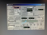
During a routine self test it did not recognise any of the 3 possible inputs (BNC, XLR and Toslink) and threw "check connections" error. In normal instrument operation digital input voltage readout is always few millivolts. Only exception is BNC to BNC (cable loopback) when output is set to 2.5Vpp and Hi-Z the input readout is 2.9Vpp (?!), at 2.2Vpp output readout is 1.9Vpp and below 2.1Vpp output readout is always few millivolts. No more working (always few millivolts) if set to 75 ohm. The same with no cable connected an GenMon input or any other combination XLR and Toslink. It looks there is a kind of crosstalk because if I connect BNC to BNC and set input to XLR I still say valid data but voltage is, again, few millivolts. I probed the output of digital generator with an oscope and signal is OK.
So I am starting checking for any clue. I noticed on the digital connectors board there is a MAX310 multiplexer. Should I start replacing it? I know there are very competente users about AP old stuff. Like Audio1Man user. So it's great if someone could put me in the right direction.
Lack of schematics does not help for sure.
Thanks!
Hi danilsSo my Christmas present this year is the digital input of my system two 2322 dying with no prior notice.
During a routine self test it did not recognise any of the 3 possible inputs (BNC, XLR and Toslink) and threw "check connections" error. In normal instrument operation digital input voltage readout is always few millivolts. Only exception is BNC to BNC (cable loopback) when output is set to 2.5Vpp and Hi-Z the input readout is 2.9Vpp (?!), at 2.2Vpp output readout is 1.9Vpp and below 2.1Vpp output readout is always few millivolts. No more working (always few millivolts) if set to 75 ohm. The same with no cable connected an GenMon input or any other combination XLR and Toslink. It looks there is a kind of crosstalk because if I connect BNC to BNC and set input to XLR I still say valid data but voltage is, again, few millivolts. I probed the output of digital generator with an oscope and signal is OK.
So I am starting checking for any clue. I noticed on the digital connectors board there is a MAX310 multiplexer. Should I start replacing it? I know there are very competente users about AP old stuff. Like Audio1Man user. So it's great if someone could put me in the right direction.
Lack of schematics does not help for sure.
Thanks!
1. if toslink works the MAX310 may be OK
2. The LM6172 is typ the failure for big signal inputs
duke.aguiar@ieee.org
My 2522 was broken 3 times and always it was Fairchild logic chips(SSOT24 MUX or DEMUX I don't remember but you'll easy to see them). Interesting, that nearly to these chips are Ti's similar chips and they are still fine.
In one case 2522 digital input was broken but anyway, the problem was Fairchild logic.
In one case 2522 digital input was broken but anyway, the problem was Fairchild logic.
Hi danils
1. if toslink works the MAX310 may be OK
2. The LM6172 is typ the failure for big signal inputs
duke.aguiar@ieee.org
Hi duke,
1. Yes, toslink does work but there's something strange going on: I connected toslink output and input with a cable, but if I switch to XLR or BNC output, I am still reading a valid signal with toslink port input selected, so it looks like the input is active on toslink, BNC and XLR at the same time... I think I am supposed to lose the signal if I switch the output from Toslink to either one of the other ports. Problem does not look to be on the output side because I checked with oscope that switching the output port, inactive ones have no signal.
Just for reference, you can see also with the GenMon option I have no signal amplitude readout, and this is the issue that triggers the "check cable connection" during system tests.
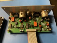
2. I did not find LM6172 on the digital board. I found LM6171 (voltage FB opamps) on the main board ("1" in the picture) and CLC432 (current FB opamps) on the input board, please find in attachment photos of my boards. Which one do you refer to? Maybe you have in mind another board revision?
Any clue?
Thanks and merry Christmas!
Attachments

Some PCB'S used single OP's others used Dual. Follow the signal path with a scope. Email me duke.aguiar@ieee.orgHi duke,
1. Yes, toslink does work but there's something strange going on: I connected toslink output and input with a cable, but if I switch to XLR or BNC output, I am still reading a valid signal with toslink port input selected, so it looks like the input is active on toslink, BNC and XLR at the same time... I think I am supposed to lose the signal if I switch the output from Toslink to either one of the other ports. Problem does not look to be on the output side because I checked with oscope that switching the output port, inactive ones have no signal.
Just for reference, you can see also with the GenMon option I have no signal amplitude readout, and this is the issue that triggers the "check cable connection" during system tests.
2. I did not find LM6172 on the digital board. I found LM6171 (voltage FB opamps) on the main board ("1" in the picture) and CLC432 (current FB opamps) on the input board, please find in attachment photos of my boards. Which one do you refer to? Maybe you have in mind another board revision?
Any clue?
Thanks and merry Christmas!
Dear Duke, I am going to mail you but I got some interesting findings for other users that could have the same trouble. Faulty part about missing input signal voltage could be that opamp that is part of signal conditioning before multiple input ADC that I think measures the input voltage amplitude on digital inputs.
It looks there are oscillations at the output and a big temperature drift if I put my finger on the opamp.
Aside of this, there is a 1:1 signal transformer before and I found no output on the secondary winding, despite it does not look interrupted (0.32R resistance as per data sheet).
Another issue I am experiencing is, if I connect digital XLR output to XLR input and I switch to BNC output and BNC input I'm still receiving a valid signal, that does not look a correct behaviour. A first check of the MAX310 multiplexer on the inputs board looks it works properly.
I'll keep you updated about how situation evolves
Attachments
@danils
I seldom use digital IO on my 2322 but this is what I get:
With input to GenMon and no cables connected I see fair tracking of input to output levels and correct data down to low levels (only below 200mV the XLR seems to catch more noise and give significant higher reading than BNC)
So it looks like your main problem is what I marked in boldface in the quote and maybe you could concentrate on the GenMon path first. That behavior (going from clipping to signal drop-out just by varying send level, and no signal when terminated) is weird...
This is basically an illegal operation mode (user error) and thus I think what we see is completely OK. We get a reading and we get a behavior but it must be ignored as we are in the wrong mode wrt to the actual connection.
Takeaway: basically we should always remove the input connections not in use to avoid seeing semi-plausible but actually incorrect signals from wrongly selected inputs. Yeah, AP should have impemented this with true muting / 1:N select to avoid user errors but for probably technical reasons they didn't.
Hope this helps.
I seldom use digital IO on my 2322 but this is what I get:
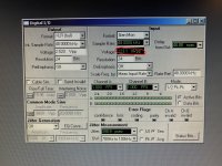
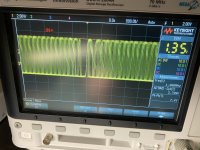
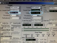
In high-Z mode the input clips at ~3Vpp ("1.5Vpp" send level). Below that it follows the 2x relation nicely (and 1x when terminated), down to 20mV levels.Only exception is BNC to BNC (cable loopback) when output is set to 2.5Vpp and Hi-Z the input readout is 2.9Vpp (?!), at 2.2Vpp output readout is 1.9Vpp and below 2.1Vpp output readout is always few millivolts.
No more working (always few millivolts) if set to 75 ohm. The same with no cable connected an GenMon input or any other combination XLR and Toslink.
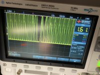
With input to GenMon and no cables connected I see fair tracking of input to output levels and correct data down to low levels (only below 200mV the XLR seems to catch more noise and give significant higher reading than BNC)
- output XLR and BNC : gain of 2x (eg 1V --> 2V), regardless of input terminations
- output others : gain of 0.5x (eg 1V --> 0.5V) , regardless of input terminations
So it looks like your main problem is what I marked in boldface in the quote and maybe you could concentrate on the GenMon path first. That behavior (going from clipping to signal drop-out just by varying send level, and no signal when terminated) is weird...
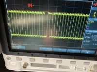
Switching input to BNC I/O while having XLR connected gives some 17mVpp reading here, not changing with output level and with error flags coming on at any send level. Switching to High-Z gives wrong reading (the same 17mV) but now I get correct transmission down to 1.1Vpp send levels.Another issue I am experiencing is, if I connect digital XLR output to XLR input and I switch to BNC output and BNC input I'm still receiving a valid signal, that does not look a correct behaviour.
This is basically an illegal operation mode (user error) and thus I think what we see is completely OK. We get a reading and we get a behavior but it must be ignored as we are in the wrong mode wrt to the actual connection.
I'm seeing this here as well, so again I think this is the intended behavior (and yes, I was also puzzled by this odd behavior). The settings and reading will only be correct when switching both input and output to optical.toslink does work but there's something strange going on: I connected toslink output and input with a cable, but if I switch to XLR or BNC output, I am still reading a valid signal with toslink port input selected, so it looks like the input is active on toslink, BNC and XLR at the same time...
Takeaway: basically we should always remove the input connections not in use to avoid seeing semi-plausible but actually incorrect signals from wrongly selected inputs. Yeah, AP should have impemented this with true muting / 1:N select to avoid user errors but for probably technical reasons they didn't.
Hope this helps.
I also note the sections in the manual about digital I/O's, on page 8-7ff:
Note that the digital Gen Mon connection is electrically made to the center conductor of the BNC or across pins 2 and 3 or the XLR, whichever is selected as the digital output connector on the DIO panel. This point is therefore subject to loading by the input impedance of the device under test, [...]
...
The peak-to-peak signal amplitude of the serial pulse train at the front panel XLR or BNC (input) connector selected in the Format field is shown in the Voltage display. The display is not operational when optical or the rear panel general-purpose serial or parallel connectors are selected.
...
The XLR, BNC, and optical (output) connectors are all functional whenever any one of these three is selected in the Format field.
The actual output voltage/light intensity will correspond to the setting in the Voltage field only at the connector selected in the Format field, with the voltage/light intensity at the other connectors being in error.
I think that settles most of the other questions wrt to signal flow.
So it looks like your main problem is what I marked in boldface in the quote and maybe you could concentrate on the GenMon path first. That behavior (going from clipping to signal drop-out just by varying send level, and no signal when terminated) is weird...
Thank you for the useful insight! The same here, I almost never use the digital I/O part of the 2322 because being limited to 48k makes it almost useless for my purpose. So I struggled to remember how it was the normal behavior when it was operating. Btw I'd like to have it operating properly and learn something about the device trying to fix it (stunning piece of artillery still today...)
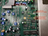
TBH all the measurements in the digital domani (FFT, etc.) are properly working, only the input digital voltage amplitude is messed up. So spending hours following the signal path, I came to the conclusion that the digital signal is redirected to that ADC chip in my picture that reads that amplitude. Before entering the ADC the signal is conditioned by that elantec opamp as per my picture and some measurements underline oscillations at the output, plus a temperature drift if I put my finger on the opamp. The failure mode is consistent with measurements because increasing the amplitude at input, the output of the opamp suddenly jump to the value that gives a reading of 2.1V on the user panel. I managed to find the same opamp on ebay and I am waiting for it. Thankfully it is in a quite easy position to be replaced without disassembling the DIO board.
Let's see what will come out 🙂
I checked the GenMon path with the scope and the set output voltage on the user panel is consistent with the measured value.
My understanding is that they routed the signal throught the lowest possible number of components in order to avoid affecting measurement precision (it would be not audio precision indeed lol). I sometimes had the impression that there is not a robust ESD protection on the signal path, relying on internal clamping of ICs and I am suspecting it could be the root cause of my fault. I'm guessing tho. Another user in the thread pointed out he got several faults on multiplexer of the same brand, maybe because of poorer ESD protection compared to the other brand? Again...guesswork.Switching input to BNC I/O while having XLR connected gives some 17mVpp reading here, not changing with output level and with error flags coming on at any send level. Switching to High-Z gives wrong reading (the same 17mV) but now I get correct transmission down to 1.1Vpp send levels.
This is basically an illegal operation mode (user error) and thus I think what we see is completely OK. We get a reading and we get a behavior but it must be ignored as we are in the wrong mode wrt to the actual connection.
I'm seeing this here as well, so again I think this is the intended behavior (and yes, I was also puzzled by this odd behavior). The settings and reading will only be correct when switching both input and output to optical.
Takeaway: basically we should always remove the input connections not in use to avoid seeing semi-plausible but actually incorrect signals from wrongly selected inputs. Yeah, AP should have impemented this with true muting / 1:N select to avoid user errors but for probably technical reasons they didn't.
Hope this helps.
It helped so much, thanks!
Hopefully the OpAmp swap fixes your issue ;-)
Given that the design of the 2322 is more than 20 years old I think we can live with it's shortcomings (one of them is less than perfect serviceability).
ESD (or general overvoltage) protection sure isn't stellar but one could argue that this often is user error. So far I've been lucky...
Given that the design of the 2322 is more than 20 years old I think we can live with it's shortcomings (one of them is less than perfect serviceability).
ESD (or general overvoltage) protection sure isn't stellar but one could argue that this often is user error. So far I've been lucky...
And last but not least, 20 years is the guaranteed data retention of CPLD / FPGA. Some of those old AP boxes (mine included) are over that period. So I am also quite anxious of switching it on one day and get erratical behavior because firmware starts to go nuts.Hopefully the OpAmp swap fixes your issue ;-)
Given that the design of the 2322 is more than 20 years old I think we can live with it's shortcomings (one of them is less than perfect serviceability).
ESD (or general overvoltage) protection sure isn't stellar but one could argue that this often is user error. So far I've been lucky...
The smart move would be trying to extract those firmware with a programmer (if ICs are not read-protected) and store it for eventual part replacemente.
I think AP would not complain about IP violation because it is old, EOL and not serviced anymore equipment.
That said, if I think about the prices those old AP boxes are currently sold on the internet, I think they are all overpriced. Not because their performances do not worth the price but because they are basically time bombs waiting to be disposed of if a fault triggers in a FW-containing part.
Yeah, buying potential time bombs (simple but unrepairable faults when a programmed/digital or unobtanium part fails) is an issue with any old and complex measurement gear and AP units which are 20+ years old are certainly overpriced most of the time. Mine is now 25 years old and I'm aware it might blow up any time.
In the days of Compuserve user groups, there were a number of folks in the HP/Agilent and TEK universe who described how to copy the code in the EEPROM
Replacing the opamp as per my post #7 fixed the issue. Now the signal amplitude is consistent and the test procedure correctly pass the relevant test.
Hope it provides guidance to people experiencing the same problem on their equipment.
Hope it provides guidance to people experiencing the same problem on their equipment.
Attachments

- Home
- Design & Build
- Equipment & Tools
- System two SYS-2322 digital input dead