Local feedback between grid-cathode

Hi,
I was investigating about generic feedback and its use and I ran into a particular local feedback loop between grid and cathode of a tube (triode, ecc.). I noticed it's employed especially in certain guitar amps. I wondered if it has any use in tube audio systems too. And how to calculate the the proper cut-off frequency for a generic case. Some informations of the subject are messy.

Attachments

  • Immagine.jpg
    Immagine.jpg
    35 KB · Views: 1,198

Orion HCCA 2100

Ive got a weird problem with this one, which if I hunt around some more I'll probably figure out but currently has me scratching my head.

Amp came in said to power but not produce output. After fumbling a minute, I found only half the power supply fets were operating, and the other half only intermittently. This causes only half the audio circuit to see rail. I believe I narrowed the issue down to the one sides' PS fets MPSA06 drivers not (always) seeing positive rail voltage on collectors and therefore the drive signal from the TL494 is not always getting past the drivers. I say not always because I can let the amp half idle and sometimes that PS will briefly start up. When it does, the signal on the FET gates looks shaky and weak and dies almost instantly.

I removed the two sets of MPSA06/56 from the PS thats not operating correctly and I get fluctuating positive voltage on the MPSA06 NPN collector. All other pads look good including the drive signal, ground, and pulldown. To me it seems like something is dragging the positive supply voltage down after the 68Ohm 3w resistor, whereas on the good PS all NPN collectors are stable at 3.4vDC. The 10uf axial caps at these 68ohm 3w resistors are OK.

Theres a 2n6488 standing up between the PS toroids which is connected to the intermittent PS drivers, and directly connected to the MPSA06 NPN collector. If I remove the 2n6488, I get stable ~12vDC on the pad of the PS NPN collectors. Re-installed and I get anywhere from 0v to 7vDC on the NPN collector pads - fluctuating.

What could be dragging/fluctuating the drive circuit components you think? Is there a schematic or drawing for this area of these type of amps anywhere?

Redesigning JmLabs Electra905 crossover

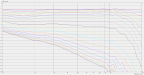
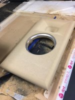
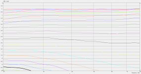
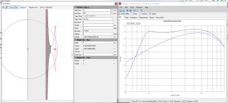
Hi guys, I have been working on this for, well on and off, years now, trying to find a good solution. I bought a pair of electra 905's from the Focal distributor around 7-8 years ago, maybe longer. I got a good deal, but at the same time, I spent so much, I can't bring myself to move on to a new equal level DIY project. I've built smaller projects using focal drivers, some seas projects, etc. I like certain attributes of the Focal's, certain others not so much. Anyway, I decided to finally test my crossover skills, or lack of, on the factory crossovers. I asked the distributor for the factory crossover schematic, which he sent. I measured the drivers in the factory enclosure without a crossover, one at a time. Unfortunately, when I pair up the midbass drivers, I get a really strange measurement, and I'm not really sure how to properly do this. I talked with someone else who mentioned that I could get a reasonable approximation by just telling the crossover software I have two of these midbass drivers, but only measuring the one. My concern is that, well they aren't the same, one is on top, the other on bottom, so the distance between the two is over a foot, and it seems like this isn't the best method. None the less, I do think I am getting a reasonable approximation, so I put the factory crossover into my software, and came up with a graph, using my actual measured responses. I then tried to come up with my own crossover, adding some baffle step compensation, a better contour, and even a notch filter. Before building this, I wanted some opinions on what I have. First I will post my response charts, maybe someone can tell me if, from those, something looks funny. Then when I get a schematic for the crossover together, I can post that.

Attachments

  • electra905oe.gif
    electra905oe.gif
    15.5 KB · Views: 365

Amplifier Clipping or Speaker bottoming out?

24, 2022 - 9:54pm

Hi All.
Yesterday I was listening at pretty loud level (according to Phone SPL meter 83db average with 87db peaks at distance of 9 feets from the speakers) and I did hear I belive "thumping" noise from the Low Frequency driver of my Sonus Faber Olympica 2 speakers only on the drum kick parts of the song (was playing Max-O-Man song by Fourplay on TIDAL 16bit/44khz).
I could see the woofer doing very long excursions but I'm not sure weather I was clipping the amp or was pushing the limit of the speaker. The amplifier is Primare I35 Prisma which according to hifinews can deliver 190W / 395W Continuous power (<1% THD, 8/4ohm) and 192W / 415W / 510W / 260W Dynamic power (<1% THD, 8/4/2/1ohm).
The volume control of the amplifier was at 70 out of 100 units. According to Sonus Faber user manual, the speakers can handle 50 – 250W and the Long-term max input voltage (IEC-268-5) is specified at 20 V rms.
So, does anyone have clue what is happening, am I clipping the amp or is it the speaker defective or is it the song having just to much low bass notes?

Aleph 30 weak bass

Hi, I have an Aleph 30 from about 2004 that exhibits weak and distorted bass; midrange and treble seem fine. I've measured the rail voltages, bias currents and output offsets and all seem fine. Although physically, everything looks fine, I'm suspecting the 16+ year old power supply caps. Does that seem reasonable, or is there something else I should be taking a closer look at?

Metalwork tips and tricks for Cabinetry.

Hi All.

I thought about writing this thread as I am often making things, and whilst I am practical I am constantly blown away by the knowledge of the 'practical' types of the generation senior to me.

I intend to keep this thread as concise as possible, and it was somewhat inspired by a recent thread posted about panel drilling and broken drills.

Question:

I often drill aluminium cases, sometimes 10mm Copper or Aluminium plate, up to perhaps 1/2".

The single largest issue I find is binding of aluminium swarf onto the tool face, be that jobber drill, carbide mill, file, cone/step drill.


What lubrication, or methods can I use to keep clean/clean off the tools?

Will the right cutting agent prevent this binding of Aluminium to the tool?


I mean...in all honesty, I prefer trying to work Copper 🤣

Do MSO/multisub systems show improved waterfall / ETC / CSD plots?

I have seen dramatic before and after frequency response plots of a single sub vs. after MSO tuning of a multisub system.

However I haven't seen before and after waterfall or energy-time or spectral decay plots - (I have seen the big improvements from active bass traps a la Bag End or AVAA.)
I presume these are improved too because the MSO tuning to an extent makes each sub cancel the standing waves from the other subs?

Cheers

class A Buffer

I have attached the schematic and board layout for the buffer. I plan to copy and make 2 channels on the same pcb and use a single heatsink (along the length of the pcb) for all the 4 transistors. Any issues with this.
Do I need both R4 and R5 for ring of two ccs stability.
How does the layout look.

Attachments

  • schm.png
    schm.png
    90 KB · Views: 2,765
  • brd.png
    brd.png
    77.2 KB · Views: 2,569

Audio research VT200 Biasing & Schematic

Since Audio Research Corp. will not provide a PCB schematic for the biasing of my VT200 behemoth I would request anyone with a circuit board scan and/or schematic to come forward. Although I can do this with merely their 2 page biasing instructions I also know any tech, even at ARC, would refer to a detailed image of the printed circuit board component values and test points.

Thanks,
John

Philharmonic Audio BMR Tower clone -- 2 Tectonic TEBM46C20N-4B or 1 Vifa NE123W-08 or TC9FD18 FAST/WOW ?

I have these woofers -- ScanSpeak 22W/8857T
I have these tweeters that I like -- Vifa XT25BG60-04 and HiVi RT1C-A
This mid, but I'm not sure I like it -- Dayton RS52AN-8 (TC9FD18 has 3.57 times the Vd of this driver)

Thinking of getting 2 Tectonic TEBM46C20N-4B or 1 Vifa NE123W-08; which one is better option?
Or stick with RS52?

I might just given up and go with TC9FD18 FAST/WOW. I'm not really into dome tweeter like highs.

I think a rough clone of the Philharmonic Audio BMR Towers would be okay.

I've never seen a speaker or can't recall, with one of the most expensive tweeter and woofers and then cheapest mids, so I figure the BMR's must be okay. And the build quality is acceptable to me on the BMR's, from what I see in the pics. I also require a really good horizontal dispersion pattern. But I need the drivers to "sum" at a close distance also. Around 2 meters.

Attachments

  • A7C03063-683x1024.jpg
    A7C03063-683x1024.jpg
    89.9 KB · Views: 232
  • A7C03064-scaled.jpg
    A7C03064-scaled.jpg
    252.1 KB · Views: 409

Yamaha RX-V2500 servicing

Hi
Just for fun, I want to service my Yamaha RX-V2500, it is not in use at the moment and I already exchanged the flipflop IC and C4 cap and improved cooling by adding a resistor to the fan powersupply, now it has a 100 hz hum in all speaker outputs, it is always there, not loud but hearable...any thoughts what could cause that, I am planning to exchange the big powersupply caps, could those be the problem?
Thanks for any info and tips,
Tojoko.

bypass capacitor in a speaker, same type?

Hi Everyone,

I'm hoping some one with empirical experience can help me. I have clarity caps in my tweeter crossovers and wonder what you've tried. Pure theoreticians need not feel obligated to contribute. 🙂

I know many try to roll together more expensive sounding caps by mixing medium quality with small bypass high quality caps.

I'm wondering if anyone has tried bypassing caps with the same kind? For instance, a Janztzen superior 4uF with a Jantzen Superior 0.1uF or the likes. Is it worthwhile, or is it more worthwhile when mixing up caps?

I was thinkng of bypassing the Clarity's with other clarity's, but their bypass caps are expensive, like $30 for 0.1uF. I'm trying out Audyn True Coppers right now, at about half the cost of the CC's. Still about 5 days short of their break-in period.

Thanks,

Erik

Question about class D amps in general and FX502S PRO in particular

Hi Guys - first post here:

The amp FX502S PRO I have gets quite warm when I am not using it but then the temperature drops considerably when I am listening to some music. Is this normal for Class D amps or maybe the OpAmps self oscillate at high frequency?

This was happening with the original NE5532 OpAmps. I replaced them with OPA2604 - the same situation in terms of temperature.

Speaking of sound difference - it is really difficult to tell, however one of the channels now have popcorn noise that is clearly noticeable when I crank up the volume to max without any audio input. I got the OPA2604 on AliExpress - they were used so I am guessing one of them is shot.
By the way OPA2604 appears to have much less gain than the original NE5532.

Not wanting to admit defeat and go back to the NE5532 I ordered SOIC8 to DIP8 adapters with OPA1656 installed.
OPA1656 is high gain bandwidth product - so if there is indeed self oscillation - I don't think this OpAmps will solve the problem.

I don't have access to oscilloscope - is there any other way to check for self oscillation?

Cheers,

E.D.

Easiest cabinet for Fostex FE206en

Hello All, I have the oppertunity to get a used pair of Fostex FE206en drivers.

I used to have these drivers in some very elaborate cabinets & the fostex back loaded horn and absolutley loved them.

I am not in a position to have big speakers any more ( wife!) and I cant build anything complex.

Can any one recomend a very simple cabinet for a fostex fe206 please?

I`m not looking for the ultimate & bass extention isnt important - I just need something slim and easy to build that the wife wont hate.

Currently using frugal horn mk3 with 4inch drivers.


Thanks

Help - my Infinity TSS-SUB500 is making a weird noise and the standby light is flickering.

Noise is as if it is being played and outputted through the subwoofer even when it isn’t even plugged into my receiver. Keeps making the noise when I play audio and it sounds very distorted. The speaker is designed to turn on from standby automatically when an audio signal is present. Sometimes it works fine but 100% of the time about less than a minute after no music is being played, it goes into standby mode which is when the light begins to flicker and the subwoofer will make an odd sound. Sometimes it makes the odd sound even when playing music which makes any bass sound very distorted and the standby light continues to flicker between red(standby) and green(on).

I posted a video of the sound it makes on Reddit (they redirected me here): Login to view embedded media

Upgrading Sanyo type SK 522 3-ways bass reflex for wallhanging

Greetings fine gurus.
I intend to renovate and upgrade these beauties. They are for a friend to hang on his walls a meter or two from each side of his TV. They will be driven by his Denon AVR with Audysey.

I will make a test-baffle for the drivers

Should I align acoustic centres to limit delay?

I ripped a pair of Proson stand mounds, and hope I can use some of its components to create a decent crossover

Do you guys think its doable? I have some hi end car networks with more parts

1643136969832.png


Here is the original filter:
1643137644658.png


Here is the donor which hopefully will provide some of the components. I may have some more lying around
:
1643137864297.png


The little ones:
1643140362698.png


Cheers!

Luxman F-105 problem

Just a shot in the dark here. I have a Luxman F-105 with no audio output. There is a blown 1/4 watt resistor near a voltage regulator which I suspect is the cause. The markings are burnt off so I have no way of telling what the value should be. Oddly it's in series with a 2 watt 12 Ohm resistor . Would anyone here have access to a service manual for this piece ? The resistor number on the board is R809. See pic for an idea - the 2 watter is the one beside the regulator and the blown resistor has been removed . TIA for any help. Mike.

Attachments

  • IMG_1510.jpg
    IMG_1510.jpg
    629.4 KB · Views: 296

For Sale Sonus Faber Grand Piano Domus MINT CONDITION

Sold!!


Another sale because I have to make room for my new speakers and now they are in my storage room:
A pair of Sonus Faber Grand Piano Domus in mint aesthetic and working condition.
Located in Malaga Spain, shipping within EU should be like 100 to 150€ maximun.
I have the original boxes (and documentation) as can be seen in pictures.
Asking 1300€ + Shipping + PP fees if apply, a real bargain


Elekit 8600S

Hello all

i have just purchased a Elekit 8600S from the diy store .
Hiwever i would like some advice about possibly purchasing a second unit and run them as monoblocks ? I have never done this before and am unsure how to hook the system up ? Is it ok to only connect 1 speaker to each monoblock ?? Stress on the output transformer esp with a tibe amp - ? Do i parallel the speaker connections

what would be the sonic benefits of running them as monoblocks ??

Anyone run drivers full range (no crossovers) in their DIY speakers and prefer it? Li

Like epos es did.

Obviously you can't do it with tweeters because you'll fry them, but does anyone do this and like the sound?

One of my favourite speakers over the years have been the old British epos speakers, es range. These were infamous for never using crossovers at all. Apart from a capacitor on the tweeter which acted as a high pass and stopped low frequencies destroying it. Of course the cabinets become a tuning mechanism and drivers have to be sourced or spec'd to roll off appropriately, possibly, but they were a very successful speaker here in the UK. And obviously component matching was another factor, lots of naim users liked them, because they were designed on naim amplification.

I have to say owning hundreds of speakers over the years epos were always one of my favourite and they did have a sound which others I thought couldn't quite match in certain areas. I know their designer Robin Marshall was a bit of an advocate against crossovers at the time.

But anyway anyone have similar feelings about no crossovers or using drive units in such a fashion with good results?

A crossover of whatever form is allways another thing to send a signal through after all. It influences the sound.

Screenshot_20210415-165513_(1).jpg

Which woofer should I use for Audioengine A2 replacement?

Cut to the chase, I need new woofers.

And this one stands out among the rest due to how low it can go:

Option 1
An externally hosted image should be here but it was not working when we last tested it.

An externally hosted image should be here but it was not working when we last tested it.


However I am concerned about the rising bass response. Since Audioengine A2 already has its own bass boost that it is known for. I would be fine with either one of the bass boost for a small speaker, but both combined would probably be too much.

Option 2 - Less bass, higher FS
T2NK2dXg8XXXXXXXXX_!!725684343.jpg

T2TG6dXnxXXXXXXXXX_!!725684343.jpg


Options 3 to 9001 (All roughly around the same feeling) - Bass starts falling at around 100Hz, Fs over 100Hz.

But this particular unit catches my attention because it does not lose too much 1kHz - 2kHz unlike other 3", including Audioengine A2. It also has a low Fs.

TB2AAt6XZH_F1JjSZFKXXbcvFXa_!!3364615349.jpg

TB2o7cZXwD8F1Jjy0FoXXbcmVXa_!!3364615349.jpg


I understand that these frequency charts need to be taken with some iodine sea salt. My aims are 1) Give the modified A2 as much bass extension as possible (The stock woofer's extension is horrid), but at the same time 2) Fix the rancor pit at 1kHz.

And 3) Avoid changing A2's own EQ if possible. I am fine if the speaker's own frequency response is completely flat, because I run a similar bass boost on my Marantz amp and I love it.

In this situation, which woofer is the best? If not for the rising bass response, I would have chosen the first one due to bass extension. Or does anything with a low Fs work? In that case I can choose option 3.

Thanks a lot.

Why is my measurement so horrible?

Up until now I always built my crossovers by using modeling software and FRD and ZMA files provided by the manufacturer (or I traced graphs if not provided). Recently I bought a measurement mic, the Dayton iMM-6 (the TRRS thing). I started a cheap project to get to know the process, a small 2-way based on the Dayton TCP115-4 midbass and ND25FA-4 tweeter.

First I imported the drivers' provided FRD files in VituixCad and generated versions with baffle step and diffraction taken into account (based on baffle dimensions and driver placement).

Next I did driver measurements. I assumed the responses would look a lot like the provided FRDs (with step and diffraction effects). But they were far off.

Below is the measured (gated) and modeled unfiltered response of the tweeter. The midbass driver did a bit better, but still far off the provided FRD.

Any idea why? Would it help to use a different mic, like a UMIK-1 or something? Or do you think the measurement is correct, and the provided FRD is just way off?

Attachments

  • Measured vs modeled.png
    Measured vs modeled.png
    58.7 KB · Views: 762

Any resemblance to actual speakers and related concepts is coincidental

Hello!
I share with you a project considered and designed for years.
The project is 3 strips, each strip in its own volume.
First to show the speakers involved in the project.
https://photos.google.com/share/AF1...gcKI7snz0zc60A?key=ZHdEdndCcXotTS1NSHR1VXnXve
Bas
https://www.visaton.de/index.php/en/products/drivers/woofers/tiw-300-8-ohm

Among:
https://www.visaton.de/en/products/drivers/woofers/al-170-8-ohm


High frequency
https://www.visaton.de/en/products/drivers/ribbon-tweeters/mht-12-8-ohm


On the next link you can see the process of making the volumes.
The materials are birch plywood
https://photos.app.goo.gl/ypTtccbxvq4QMqbz8

In the following link the volumes are already painted by special technology.
https://photos.app.goo.gl/Spb4Zuoin8mVjo499

And here are the finished built speakers
https://photos.app.goo.gl/8j1CvY6hT7nbvJJY7
And in the following videos, in addition to seeing them, you can also hear them
Login to view embedded media

I apologize if there is a misunderstanding of the text, but I use an interpreter and mistakes are possible.

My problems with Measurement Microphones and REW

I have been using a UMIK-1 microphone for a few years but decided I needed to switch to an Audio Interface with an XLR microphone so I can do Semi-dual channel measurements. I bought a Beringer UMC204HD and a Beringer ECM8000 microphone. My problem is the measurement range, if I try to measure at 75db at 1 meter I have to set the level on REW to -36db or the peaks are all flat. I thought the ECM8000 was the problem so I sent it back an got a SonarWorks SoundID Reference Measurement Microphone. It is slightly better but it still doesn't have the range of the UMIK-1. Is it just me or are these microphones the problem. Attached shows my problem, green is -30dB, red is -27dB and purple is -24dB. The problem is easy to spot, 95.5bB maximum around 10khz.

Attachments

  • Microphone.jpg
    Microphone.jpg
    99.7 KB · Views: 466

Kef 104 Crossover help.

Hi guys I'm doing a restoration of my girlfriends old Kef 104, the driver units are workin fine so I will change the internal wire and Capacitors and inductors and move it to a bigger wooden board because the Auricaps where much larger then the original.

I'm not good with reading shematics so I hope you guys can help me with that, when I look on my crossover at home I can see 3 capacitors and 3 inductors, but when I look on the schematic I got from internet one of the inductors have 3 frequencies? what does that mean? I've bought the capacitors now and will change the inductors in the future but I need to know what to buy🙂

My first post here and I'm from Sweden so I hope you will have som understanding if I spell things wrong.

Happy New Year.
/Mattias

Attachments

  • kef104.jpg
    kef104.jpg
    36.3 KB · Views: 971
  • KEF104Crossover.gif
    KEF104Crossover.gif
    7.6 KB · Views: 1,117

LTspice model for Dynaco A470 Output Transfomer

A while back I posted a message concerning LTspice models for output transformers and got some helpful guidance. Thanks to everyone who offered advice.

Rather than tackle a generic U/L transformer model complete with a drop down list, I decided to start small and create a simple .asc file for a single transformer: the Dynaco A470 for the ST-70 power amp. I've attached that file here.

Drawing the symbol was easy enough but determining the appropriate inductances for the transformer sections turned out to be more difficult than I thought it would be. I tried using Robert McLean's excellent spreadsheet but I suppose I don't understand that as well as I thought I did. Could someone help me out with the inductance values for L1 through L7, possibly including series resistances? If it's easier to get the specifications for the Hammond 1650N (which has the same 4300 ohm primary impedance) I'll be glad to use that instead.

My goal is to figure out how to do this once so that I can create additional models for the Dynaco Mark III output transformer (model A431), and the Plitron PAT4004 and PAT4006. Any help you can provide to educate a newbie would be greatly appreciated.

Thanks in advance.

Ray

SUPRAVOX 400 GMF - 15" / 97dB / 20Hz - 5000Hz / 8 Ohm / 38cm / 120W

FS: SUPRAVOX 400 GMF - 15" / 97dB / 20Hz - 5000Hz / 8 Ohm / 38cm / 120W

A brand new, unused matched pair of Supravox 400 GMF drivers.
I bought 2 pairs, but only one is enough for me.
RRP: €1500
Made in France.

70d1071352218630.png


  • Membrane material: Paper;
  • Efficiency: 97dB;
  • Usable frequency range: 20Hz - 5KHz;
  • Impedance: 8Ω;
  • Power: 120W;
  • Fs: 21Hz;
  • Re: 6.5Ω;
  • Qts: 0.2;
  • Qes: 0.21;
  • Qms: 10;
  • Mms: 70g;
  • Bl: 19.6;
  • Cms: 0.47;
  • Sd: 855 cm2

Photos:

c4fb321352759082.jpg
55a3101352759079.jpg

9924bc1352759054.jpg
b1d72e1352759060.jpg


Asking price for the pair: €999

Will be shipped securely.

========

Location: Sofia, Bulgaria
Contact me here or on email veselin.karavelov@gmail.com

Single-secondary transformer for no coupling caps amplifier

This is a way to use a single-secondary transformer in a dual rail supplied amplifier with no coupling capacitors.
To achieve that, I used an OpAmp (LTP can be used too if one wants discrete solution) to split single rail into dual-rail PSU.
The 24V AC gives about 32V DC after rectification and filtering and we turn it into +/-16V DC by using a voltage divider (R3,R13) and applying its middle node to OpAmp's input so the feedback loop keeps amp's output at the same potential (which we declare to be a ground so the output sits on zero volts potential and the 32V supply voltage turns into +/-16V maintained by OpAmp).
One thing worth mentioning is that PSRR is really good, the amp is totally silent on 93dB/1W speakers (the output noise is less than 100uV and I can't measure lower than that at this moment) with only 2 x 10,000uF filtration per channel.
I chose inverting topology because my preamp is inverting too, but non-inverting mode can be used with the same result.
I tested different OpAmps (AD797, AD825, AD829, LT1122, OPA637, to name some) but the ADA4898-1 sounds best to me. Of course, each of them needs different compensation scheme to stay stable (AD825 and LT1122 are stable without any compensation - not even C10 is needed - and they sound very good too).
The gain is 20dB (10V/V, set by R7/R2 ratio). Zin is determined by the value of R2 and the feedback loop provides very low Zout (we have 3 digit damping factor here so speaker choice is not critical).
The output power is about 20W_peak at 8 Ohms load and about 36W_peak at 4 Ohms load which i consider more than plenty for home use.
The bias current of the output stage is set by voltage drop at D1-D4 diode string - 4 diodes give about 350 mA through MOSFETs (2.1V of total Vgs). If 3 diodes are used it will be about 200mA and 5 diodes will generate a bit over 0.5A bias current so you can choose in accordance with your preferences and available heatsinking, but more than 0.5A will not bring much since we here enjoy the square law output characteristic of the MOSFETs which enables them to stay "longer" in the class A regime.
Output waveforms look pretty much the same as they do here (post #1)
At the end, it sounds so good that I decided to move it into this small case (post #28) which is now a bit heavier than before (weight difference between SMPS PSU and two 80VA toroids).
Off course, one can choose the topology freely: OpAmps, discrete, BJTs, MOSFETs, etc... - power can be up/down scaled too if you wish - the main point is not to discard good single- secondary transformer just because one thinks that it makes coupling caps mandatory :cheers:

srncc.gif

srnccb.jpg

Does multiple NE5532 board need separate transformers ?

Hello,

I am working on my first DIY amplifier (class D) and I am sure how to split power supply.

The three stage of my 5.1 amp are :

  • 3x NE5532 preamp board : One toroidal 12-0-12 transformer wired in parallel.
  • 3x TPA3116 amp board : One 24VDC SMPS wired in parallel.
  • 3x UPC1237 protection module : One 24VAC transformer with three separate winding.

I am still at a stage where I test component channel per channel, so I don't know if all channel with one toroidal transformer (for preamp) is viable ?

Bonus question : How do you know the power requirement of preamp ? I took a 50VA transformer by pure guessing.

Thank you.

Suggest Newbie(ish) equipment kit recommendations please.

I am wanting to start doing my own work in replacing capacitors, installing upgrade boards, other restoration of old audio gear, etc. So I need some gear. I have previously worked on connecting power supplies and jacks on guitars, and replaced pickups in a strat, though my soldering was a mess. Got it to work well eventually after cleaning it up. In the pic below is the gear I currently have. A cheap Chinese solder gun that I purchased from a guitar pedal building site, with not very precise temperature settings, that holder magnifier extra hand thing, which needs to be mounted on something to stand up better when I am working, as it tends to fall over, that solder sucker thing, and that solder. Worked well enough for my former projects, but I always felt like I was not controlling the temp very effectively.

Was thinking about getting a used, good basic professional solder gun at least, and anything else I need for a basic kit. Also, I am looking at online courses or info for soldering techniques so I can improve that before working on anything I really care about. My goals are upgrades of Hafler amps and pre-amps, recapping, old receivers, etc., rebuilding speaker crossovers such as in my old Dahlquists, etc., recapping or etc. in old turntables, etc. And it looks like there are practice kits you can get online, and I have a couple old receivers that are not worth much I could start with after a little study/practice, that if I can get right, I will give away as gifts to someone who wants a little system. And if I don’t get it right at first, I can work to fix it, or it won’t be the end of the world if these pieces end up unusable after my practice.

So, can anyone help me with upgrading my kit? I will also add some really good lighting, as my eyes need it, and getting that Helping Hand magnifier set up right will be key.

Thanks in advance.

Attachments

  • 85D65CAC-0960-4774-A50B-6D7F3DE72E8C.jpeg
    85D65CAC-0960-4774-A50B-6D7F3DE72E8C.jpeg
    576.8 KB · Views: 113
  • 60DDD340-48D5-4756-9583-A0889963C64D.jpeg
    60DDD340-48D5-4756-9583-A0889963C64D.jpeg
    374.7 KB · Views: 117

Question for Dr. Geddes about his WG foam plug

I've read on your website a brief description and purpose of the open cell foam that you use in your wave guides. I'm looking for a little more information.

Are the foam cells random in size/distribution or are they ordered in such a way as to scatter (or perhaps absorb?) sound at certain angles to combat unwanted reflections and NOT scatter at other, more favorable, angles?

Is this discussed in any of your publications? I'm on the verge of buying your waveguide book. If this is discussed there, just might push me over the edge 🙂

Crossovers for GPA 416-8B/Altec 802-8G

I would like to build crossovers for my speakers and I need to find the right path to do this.
The following is a list of components that I would like to use:
Woofer - GPA 416-8B in 8.3 cu ft cabinet
Driver - Altec 802-8G with 511B horn
Tweeter - Altec 3000H

I am currently using the ALK AP700 crossovers that I previously used with Klipsch Cornwalls, there is no tragedy but I think it could be better because the Conwall woofer and the new cabinets are completely different.

Is there any proven ready schematic or should I measure the speakers and simulate them in the crossover software?
What measurements should I take? I have access to a measurement microphone and DATS V3.

Thanks in advance for the hints.

Sundown SAZ 1500D

This amp briefly powers with blue LED but then falls into protect red LED after about 1 second. Amp draws ~8A quickly then falls to about 2A before going into protect. I was able to determine +-15v regulators are working, but now the amp goes into protect so quickly I cant get a solid read on anything else like the +-12 and +-5 supplies. I also checked Q7, Q11, Q19, Q22 and they seem to be OK. Relay clicks twice - at REM and again when going into protect.

No blown fets. TH1 is measuring about 12k. No significant DC on speaker terminals

Any clues why it might be falling quickly into protect? Any way to keep it powered so that I can locate faults?

GPA Stonehenge V build

Great Plains Audio Stonehenge V build
In years past I owned a pair of Altec A5, and despite their shortcomings the things they did very well were dynamics, efficiency, and the way they loaded a room with sound. Having read about Great Plains Audio (GPA) of Oklahoma city making new Altec Lansing 604-8H-III two way I ordered a pair and built a Stonehenge V enclosure, decided to post my build for those who are interested. By the way if you have any questions about GPA and their products give them a call, excellent people to deal with a true American company.

Attachments

HF10AK + 12P80ND + custom WG

Hi!

I've fallen down a rabbit hole of making a new speaker with the following drivers.

HF10AK
12P80NDv2

I have designed a constant directivity wave guide using ATH4 for the HF10AK. The simulated response is flat to +/- 0.5 dB between 1k and 10k out to 45deg off axis with a drop of 2.5dB by 15k. Plots are based on 100 points, 4mm mesh resolution.

I spotted a few posts from LineSource regarding "clever" enclosures so I will try that too - it looks like the Beyma can be forced to an f3 of about 85Hz.

The Beyma is mounted such that the acoustic center is similar to the Faital and held in place from the rear with a mouting ring of alumnium.

More to follow. Thanks for looking.

Attachments

  • pic4c.png
    pic4c.png
    138.4 KB · Views: 952
  • pic5.png
    pic5.png
    43 KB · Views: 915
  • pic2.png
    pic2.png
    107.7 KB · Views: 939
  • iteration 39 chart.png
    iteration 39 chart.png
    53.7 KB · Views: 995
  • 2020-10-01 at 21.24.18.jpeg
    2020-10-01 at 21.24.18.jpeg
    186.2 KB · Views: 1,010
  • pic8.png
    pic8.png
    26.4 KB · Views: 557
  • pic9.png
    pic9.png
    83.2 KB · Views: 503

Dell system(replacing the 3.5mm jack with 2 x rca)

Im unsure of the model but it is two speakers and a subwoofer. The speakers connect to the subwoofer via an orange dsub cable(looks like a monitor cable plug kinda) . Anyway. I love these speakers, but two days ago they started cutting out in one channel and i traced the issue to a break in the cable going to the 3.5mm output jack. (Red cable was severed). Since my audio interface has RCA outputs, discrete left and right, i was going to mod the dell cable for left and right RCA instead of putting another 3.5 mm plug on.


The problem is this.


I wired the dell cable like this : white : left channel


Red: right channel


Silver:shield


Connecting to the rca plugs the same way(except i combined the shields on the two rca plugs)


But only one channel is working. I know its something with me wiring wrong/pinout because ive tried 3 different (butchered) rca plugs.


Please help? a green 3.5 mm plug came with the speakers. Inside the cable there are white , red, and silver cable. One each. I want to terminate to left and right(discrete) rca plugs NOT another 3.5mm stereo/mini jack.


What am i screwing up?

Need reasonable explanation for (Tube Amp RCA line out -> SS Amp performance)

When I pipe Darkvoice RCA line out to SS amplifier in order to listen to Sundara, the sound is so anemic and weak. It does not help to crank up volume or increase gain in my SS amplifier (Topping) - it just gets louder with no bass LOL.

But when I pipe Eufonika H5 RCA line out to SS amp, it sounds so impressively powerful to drive Sundara while retaining the awesome tube sound.

Both tube amps are simple OTL amps.

The question is, what would account for this difference...? Obviously some kind of circuit design, but would it be the more powerful capacitors in Eufonika ? Or would it be due to the fact that Eufonika has "input and output stages have separate power supply." ? Whatever the reason, the RCA out from Eufonika is so much more powerful.

Thanks...

ELMA Relay Attenuators X2 w/ IR recevier and IR remote NIB

SOLD SOLD SOLD SOLD SOLD SOLD


New in static bags; never used. Complete set costs $538.19 See attached PDF for info.

Kit No.1: The RELATT-00 unit is without resistors so you can add your own. X1 IR receiver and one IR remote.

Kit No.2: RELATT-010-64 had SMD resistors soldered in; 10K. X1 IR receiver and one IR remote..

$300 OBO Takes both kits. Shipping is $12 for USPS with signature conf. 3.3% for PayPal or send me a USPS Money order.

SHIPPING TO LOWER 48 ONLY, please.

Attachments

  • Relay-Attenuator-Datasheet-ENG.pdf
    Relay-Attenuator-Datasheet-ENG.pdf
    587.3 KB · Views: 112
  • IMG_20220124_202848.jpg
    IMG_20220124_202848.jpg
    317.4 KB · Views: 108
  • IMG_20220124_202858.jpg
    IMG_20220124_202858.jpg
    264.5 KB · Views: 121
  • IMG_20220124_202923.jpg
    IMG_20220124_202923.jpg
    360.1 KB · Views: 131
  • IMG_20220124_203005.jpg
    IMG_20220124_203005.jpg
    260.3 KB · Views: 121
  • IMG_20220124_203006.jpg
    IMG_20220124_203006.jpg
    242.5 KB · Views: 116

Expanding foam for custom seat

I need to make a seat mold for myself and I'm trying to figure out witch type of expanding foam makes the most sense. Not concerned with fire retardation since this isn't for a race car. Just something that sets up quickly and is at least somewhat durable. It would be nice if there's some flexibility/softness to it but it's not critical. Does anyone have experience or suggestions?

Multimeter limit for capacitor testing?

I'm using a Fluke 115. I was trying to test my 22000uF 35V capacitors for the power supply and I'm just wanting to get some input. It was just saying OL, so I went to the manual and it says 1 - 9999uF. I have only measured capacitors for the ACA and the moreplay I built so they were pretty low.

Am I reading this upper limit of the Fluke 115 correctly?

Identifying optimal value / rolloff frequency for coupling capacitors

I'm trying to understand the theory behind coupling capacitor value selection, specifically the desired -3 dB rolloff frequency. I understand that too low of a value can lead to negative effects, and too high of a value obviously will hamper bass response. Within that range, is there any particular logic for aiming higher or lower? Is the salient factor if and where you want to insert a rumble filter?

Advise on a 2 way kit

I’m looking for a 2 way kit with drivers and crossover only (no cabinets) and would like to spend no more than $1000-1100. I have a complete wood shop so cabinets are no problem. I would like to do a stand mount type rather than floor. They will be for music only and driven by a Yamaha RN602 (80 watts/ch). I know I could use more power but that’s what I have at this point.
The room size is 14’x20’ with 8 ft ceiling. Placement position is open to experimenting. I have looked at the Helios CM from Meniscus and the Criton 1TD-X from CSS. Has anyone heard both of these speakers and have any insight to differences? There are a number of YouTube’s on the CSS but other than the Facebook group not much on the Helios CM that I’ve seen. Thanks for any suggestions.

Protection due tue secondary ground voltage offset

Hi guys,

I've had several amps in a row which had enabled TL494 protection or not engaging the relay's due tue a voltage offset on the secondary GND (- speaker terminal).

After tracing the whole protection circuit of the amp looking for clues, it happens often that a single good reading resistor or capacitor connected to secondary GND makes the amp to go in protect. Grounding the secondary GND to the main GND with a 10k-1k resistor can mostly take the amplifier out of protect when I measure an offset.

The amplifiers are then working properly and nothing heats up or anything.
Do you guys also have the same defect sometimes? What can cause the secondary GND to have offset?

Onkyo Multichannel Receiver TX-NR1009 and TX-NR509 - no Sound at all Inputs on all Channels

A friend of me have purchased this devices in used and no working condition.
He have heard, that this defect was a typical bug, which occurs at most devices of this series after using several years.
Are there experiences about which component on the processor board represents the weak point and is causing the error ?
Thank you very much for an advice.
.
Instruction manuals are here:
https://www.intl.onkyo.com/downloads/manuals/pdf/tx-nr1009_manual_e.pdfhttps://www.intl.onkyo.com/downloads/manuals/pdf/tx-nr509_manual_e.pdfService-manuals are here:
https://elektrotanya.com/onkyo_tx-nr1009.pdf/download.htmlhttps://elektrotanya.com/onkyo_tx-nr509.pdf/download.html

Looking for a 300b SE design

Hi,

Having sucesfully completed my first KT88 based PP amp this year, I feel the urge of trying to go for a purely single ended triode design as my next project. 300B based preferrably. I'm not keen on too much iron in the signal path, so interstage transformers or mandatory input transformers are a no-go.

I am looking at a design I stumbled across a while back that I set up in LTSpice to learn about that I find quite compelling. It would be great to hear from you guys if a) anything raises red flags for you in that circuit and b) if you have other recommendations of a somewhat proven design that I should look at...

Screenshot 2021-09-29 at 23.14.04.png

Cheers,
Lars

TLBP6 - Paraflex

51097234381_f824cdc163_b.jpg
51097773043_c88a0d09ac_z.jpg


I have long thought about making a bandpass box with two transmission lines connected to the same driver. If I have understood it right, that is possible to model with Hornresp using the paraflex (PH1) configuration.

My goal is not to design anything for professional use but instead for my small living room. I am looking to make something that will dig low and hopefully also provide some punch in the mid-bass.

My living room is quite small and the back wall behind the speakers is 3,6x2,4 m. I want the sound to emanate from each corner 1/4 of the with and height of the room to suppress standing waves. In my room, there will be full corner loading up to about 100 Hz.

51074452766_fb88ce346f_c_d.jpg


The form factor I then have chosen as constraints, as furniture blocks anything wider, is 60x94 cm as also the furniture is in the way &#55357;&#56841; If I had more space I could have made the mouth larger as I believe that is beneficial in many ways. Now I have to suffice with a ratio between the driver sd and area of the mouth of 1:1.

The driver I am using is the Eighteensound 12LW800.

May I ask, what are your thoughts on this? Could it be worth making some sawdust?

51097231416_b293d7919d_z.jpg


51097327727_ccaf65f86f_z.jpg


51097313369_8d6f9dbe7d_w.jpg


51097231431_56428fa8ef_z.jpg


51097311644_81d78eb63b_z.jpg


51098036525_9efb14b3e6_z.jpg


51097773033_e53b478524_z.jpg


51097231456_daf35ce09b_z.jpg

A question regarding hornresp and end corrections for port length

Hi. I try to build for myself a sub enclosure that plays around 20ish to 40hz with the possibly best SPL and a total volume of max 600 liters. I tried some builds on hornresp for a 6th order bandpass series enclosure and got two portlengths. Hornresp has one-sided flared ports and suggests me "port end" corrections. I tried to look up on google and on the help-window of hornresp itself without any explanation of what this port end correction is supposed to be and on what port geometry hornresp refers.

Can anyone tell me when you apply this port correction and wether you shorten or elongate the port with that suggested amount? I tried once to experiment with a port length of around 2cm but hornresp still tells me to correct it by around 10cm for my 1000cm² (just an example, idk if im right here) portarea. I cant imagine that hornresp tells me to shorten the port into an impossibly negative amount. Although i have never heard of port corrections on winisd to add any aditional length to a port for a tuning correction.

Screenshot 2022-01-20 190705.jpg

🟢 DIY speaker engineering

Dear friends, I bring here a challenge from a dream of many years that is getting closer every day.
I am assembling the magnetic assembly to receive the recone kit from a commercial speaker.
It will not be commercialized but made available here in my DIY community, we have good diy amplifiers, but lack of speakers, we have absolutely nothing for a quality residential system.
This drawing is amateur, I'm not a professional designer, but I ordered a drawing in SW that will be ready soon.

JBL2235H.jpg


*I got inspired by the JBL2235H and made some changes

Attachments

  • JBL2235H.jpg
    JBL2235H.jpg
    250.5 KB · Views: 208

FS Purifi PTT6.5 Extended Stroke Woofers and Passive Radiators BNIB

PRICE LOWERED

PTT6.5 W04-01B aka PTT6.5X04-NFA-01: $500 obo per pair+shipping and PP fee
Data Sheet: <https://purifi-audio.com/ptt6-5x04-nfa-01/>
Pair 1 Serials: SN00009; SN00010
Pair 2 Serials: SN00012; SN00013

PTT6.5PR-01B aka PTT6.5PR-NF1-01: $250 obo per pair+shipping and PP fee
Data Sheet: <https://purifi-audio.com/ptt6-5pr-nf1-01/>
Pair 1 Serials: SN00001; SN00002
Pair 2 Serials: SN00003; SN00004


Hello,

I picked these up for a project that's been put on hold indefinitely.

Never mounted, never connected, brand new in original boxes.

PLEASE NOTE: The Purifi naming system has changed confusingly since purchase so to be clear: these are the "Extended Stroke" version of the PTT6.5 with Linear Xmax = +/- 10mm and Mechanical Xmax of +/- 14.5mm.

They are NOT the "6mm Linear Stroke" version of this driver.

I'll ship anywhere at the buyer's full cost. Please don't ask me to undervalue them on a customs form.

I did not get these as part of the group buy. I sincerely hope I'm pricing these appropriately; feedback on my pricing is welcome 🙂

PTT6.5 W04-01B aka PTT6.5X04-NFA-01: $600 obo per pair+shipping and PP fee
Data Sheet: <https://purifi-audio.com/ptt6-5x04-nfa-01/>
Pair 1 Serials: SN00009; SN00010
Pair 2 Serials: SN00012; SN00013

PTT6.5PR-01B aka PTT6.5PR-NF1-01: $300 obo per pair+shipping and PP fee
Data Sheet: <https://purifi-audio.com/ptt6-5pr-nf1-01/>
Pair 1 Serials: SN00001; SN00002
Pair 2 Serials: SN00003; SN00004

Attachments

  • IMG_1106.JPEG
    IMG_1106.JPEG
    742.5 KB · Views: 346
  • Driver Pair One.JPEG
    Driver Pair One.JPEG
    826.1 KB · Views: 328
  • Driver One Pair One.JPEG
    Driver One Pair One.JPEG
    532.3 KB · Views: 310
  • Driver One Pair Two.JPEG
    Driver One Pair Two.JPEG
    634 KB · Views: 305
  • Driver Pair Two.JPEG
    Driver Pair Two.JPEG
    730.5 KB · Views: 310
  • Driver Two Pair One.JPEG
    Driver Two Pair One.JPEG
    601.3 KB · Views: 198
  • Driver Two Pair Two.JPEG
    Driver Two Pair Two.JPEG
    619.7 KB · Views: 192
  • PTT6.5PR-NF1-01-Data-Sheet-2.00.pdf
    PTT6.5PR-NF1-01-Data-Sheet-2.00.pdf
    1.1 MB · Views: 88

DAC11001: New 20-bit, R-2R Precision DAC

As there were a few questions about this device in the OPA1656, I figured I would start a new thread.

The TI precision DAC team recently released the DAC11001A, a single-channel, unbuffered, R-2R DAC.

Info available at:http://www.ti.com/product/DAC11001A

Here are some highlights of this DAC:
  • 20-bit monotonic: 1-LSB DNL (max)
  • Integral linearity: 4-LSB INL (max)
  • Low noise: 7nV/√Hz
  • Code independent low glitch:
    1 nV-s
  • Flexible output ranges: VREFPF to VREFNF
  • Integrated, precision feedback resistors
  • Excellent THD: –105 dB at 1-kHz fOUT

We found some interesting needs for a device like this in control systems and arbitrary wave-form applications, where excellent DC performance was required, as well as good dynamic behavior. The device features a robust sample-and-hold subcircuit that removes code-dependent glitch behavior.

We thought it would be fun to evaluate the device for audio applications, as there are some audio designers and enthusiasts that still want that R-2R architecture 🙂

I am working on releasing an audio reference design, but that will probably be online in Q2-2020.

FS: Burning Amp BA-1 PCB, for small cases

For sale BA-1 OS boards designed by me to be used in smaller cases as a stereo single ended amplifier, with only 4 output transistors.
I attached the schematic and layout for these. They are symmetrical and can be used for left and right channel.
BA1-PCB.jpg
Photo 2022-01-23, 1 47 21 PM.jpg

Attachments

FS: Burning Amp, BA-1 assembled boards

For sale 2 Burning amp assembled boards without the output transistors.
Boards are designed by myself form the original schematic but only 2 deep, with 4 output transistors. I think is better with less output transistors and higher bias current, look at First watt amps.
This suitable for those who don't have big heatsinks and want to build a SE stereo amp in the same case.
I also have bare boards left over, and power supply boards.

Attachments

  • Photo 2021-06-03, 2 43 30 PM.jpg
    Photo 2021-06-03, 2 43 30 PM.jpg
    621.8 KB · Views: 231
  • Photo 2021-06-03, 2 43 36 PM.jpg
    Photo 2021-06-03, 2 43 36 PM.jpg
    789.2 KB · Views: 218

Audio Research $30 FET!

A friend of mine was swapping tubes in his Audio Research Reference One preamp when he bent and broke one of the leads on an FET that has a heatsink very close to a tube so I contacted Kalvin at Audio Research for a replacement "Green White Brown" FET.
What I received was a Green Green Brown FET in a mailer envelope. They charged $15 for the FET and another $15 to send it in the mailer envelope!
Not to mention the whole parts process took 2 weeks from start to finish and I don't even have the correct "hand painted" part yet.
Needless to say, Audio Research will not be getting any more of our hard earned money for their "hand painted" parts. Or any more components for that matter.
I've heard of and experienced similar situations with other companies and most of them are appreciative of you buying their products and would gladly have dropped the ten cent part in an envelope and sent it our way and not committed highway robbery. I would hate to think what tubes from Audio Research would cost?

Which woofer suits better to W5-1611SAF FR driver?

Hello everyone!

I would like to ask you for your opinion regarding plans for my first DIY speakers. I have basically two options, which I am deciding. I hope I can use one offer and buy Tang Band W5-1611SAF full range drivers for very good price. I would love to build FAST speakers with them. Honestly, I dont have much experience with speaker design, therefore I have decided to ask you for an advice regarding woofer selection.

I have generally two options (as my budget is very limited):
A: Vifa M22WR-09-08 (8")
B: Dayton Audio DS270-8 (10")

Generally, I would prefer the 8" Vifa driver, as it has lower Fs (26hz), and the 8 inch suits my "appearance design" better. However the sensitivity is 88db, while the 10" dayton has Fs 32hz but similar sensitivity as the full range (DS 90.7 and TB 90db).

Could someone please provide any opinion? I would appreciate it a lot!

Thank you and all the best in 2022 to everyone!

FM aerial advice for UK please

I have a Sony 5000F tuner lined up to join my system.
Its a vintage but good unit.

I will need to sort out an FM aerial for the roof.

Before I have used the alloy horizontal hoop type but is this the best option or am I better with a directional type?

If so are you then limited to what comes from one transmitter? If going on the roof rather than in the loft adjusting won't be an option after install.

Some things I know about, aerials is not one of them so appreciate some advice.

Thanks Rob

Power supply imbalance

Consider the enclosed power supply.

dual power supply.png

The loads on the positive and negative rail are not equal.
The supply transformer is 24volt centre tapped and the data sheet says it is capable of 210 mA RMS on the secondary.

Theoretically it ought to provide +/- 17.5 V but it provides about +/-15.7 V.
The power supply powers two OPA2134 op amps.
In addition, the positive rail feeds two additional LM317 regulators, one at 3.3V and one at 5V (for a PCM2134 DAC and a CS8416 input chip)
Both downstream LM317s output correct (and theoretical) voltages.

With this arrangement the power supply's positive rail drops to +10.5 V.
This is a bit concerning, and adjusting the resistor values around the LM317 doesn't do much to increase the output.

Based on these observations, I'm thinking maybe the transformer is undersized? Maybe a 36VCT transformer would be better?

Digital Designs Z2HV

I’m starting a new thread on this amp to keep everything straight no confusion .

I’ve been rebuilding this amp from the ground up . Since it’s been blown more then once .

I’m almost at the preamp section of this amp gonna upgrade a few electrolytic capacitors since all the other caps in the amp are new I went with Nichicon caps instead of the sam young that were In it since they were out of spec .

When it comes to opamps in this amp they are using TL074CN and BA4558 .

One of the 4558’s is bad and needs replacing .

Wondering if o could use TL072’s instead of the 4558’s? Or doesn’t it make any difference and I should stick with the 4558’s?

Massdrop noise?

Hey I have a Massdrop Cavalli tube hybrid headphone amplifier with an Electro harmonix 6922he valve and the left channel has like ssshhhhhh noise it’s like a faint white noise you know the noise that some powered speakers have naturally. You see it’s only in the left channel and I was wondering what would cause it? With nothing playing through the rca I turn it up about half volume and it nearly goes away but when I turn it up further to 100% it slowly comes back as I turn it up.
Any thoughts on this?
Cheers🙂
Projects by fanatics, for fanatics
Get answers and advice for everyone wanting to learn the art of audio.
Join the Community
507,772
Members
7,887,787
Messages

Filter

Forum Statistics

Threads
406,200
Messages
7,887,787
Members
507,772
Latest member
Hypertone