Transistor heating up on pcb.

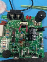
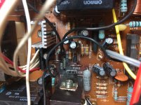
Hi Everyone, This is not related to audio but i would be great full if someone could help. I have a Petsafe RF-1010 that got hit by lightning. I’ve got the psu (18v dc) that came with it also not working although on the schematic it states using a 12vAC psu 800mA

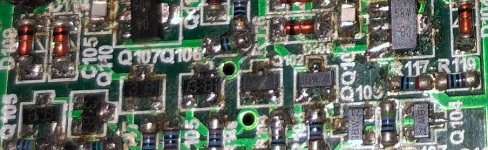
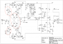
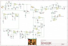
My Dc power supply showed a short straight away with increased power consumption. I detected shorts on various transistors. I replaced these. Now the unit is working at a lower voltage of 12vdc but when increased to 18vdc or powered by the AC PSU of 13vAC it is causing one transistor Q2 2N5401 to heat up real bad and the circuit is not operating correctly. Please see attached schematic.

I checked voltages and they are correct at points mentioned on the schematic 16.6vdc with 13vAc tx as power source. ( I don’t have an exact 12vAC transformer psu so nearest I can get is a 13vAC)
I replaced U4 lm741 with another similar opamp IC still no difference. I’ve checked all other components resistors caps and the zenor diodes D3 and D4 IN4148 are good.

Any ideas on where I go from here would be great. It’s strange that the circuit behaves perfectly when powered by 12vdc lab psu. But when voltage is increased to 18vdc it shuts down power supply showing a short. I have changed this particular transistor to another one of same but no change. I take the transistor out and test it on peak tester it’s perfect. So something is not a happy camper and I can’t find it when operating st suggested voltage.

Hope someone can help

paul
5A7DE508-D06C-4E0E-9E1D-2D668C5451E3.jpeg

Attachments

  • 5E8CDD93-14AE-4359-93F1-CD24A086CF9D.jpeg
    5E8CDD93-14AE-4359-93F1-CD24A086CF9D.jpeg
    624.3 KB · Views: 132

20 Hz subwoofer options - large low tuned BR or?

I plan to extend the low end of my current system with a subwoofer covering the band of 20 - 60 Hz or better, 20 - 80 Hz. The band above would be covered by a LaScala sized (mid)bass horn or a Paraflex C2D. I have a pair of RCF LF15X401 drivers that could be used in this application. This sub will be placed in a corner, the largest dimension cannot exceed 2 m.

So what are my options...I started simulating a long pipe that would work (with EQ of course). That gives me 180 l volume and a quite good form factor to place it upright in a corner:
1643015870376.png

1643015927166.png


This pipe was inspired by bentoronto and this 17ft sub. This one is slightly shorter.

And then I thought - how about the plain old bass reflex tuned to 20 Hz in the same volume box (including the vent):
1643016197519.png

1643016233495.png


A third option would be a ML-TL, but I do not feel skilled enough to design one. A sealed box of the same size would loose too much efficiency if I understand things correctly. A tapped horn would most probably not fit the 180 l limit?

My output will be limited by the excursion of the woofer anyway, so is there any point why to build a pipe/TL as a sub instead of a plain old BR? I actually see a point in bracing - a dual fold in bentoronto's style should result in a quite sturdy box with minimal effort. Also the form factor is appealing since it would allow for some easy placement in my room. On the other hand, the bass reflex box could be built in the same form factor - with the speaker close to the floor and the vent close to the ceiling.

Any thoughts on this? My idea would be to build one sub in this large size and use the other driver in a smaller box to fill in for room problems.

Attachments

Newbie Sony amp repair

Hello dear community,

I recently bought a Sony TA F170. It was hooked up to some speakers in the (charity) shop so I expected it to work. When at home however I just got terrible noise. First I discovered that the speaker foam of the drivers of the speakers had completely disintegrated.
I since then replaced the foam but I still don't get any clear sound. In fact it was working a bit on one speaker output but then slowly got quieter and finally died completely.

I'm actually more of a analog guy but since I don't know of any place that repairs such old units I wondered if a repair can be carried out by myself?
This forum is a bit overwhelming and I would love to get some step by step instructions if at all possible.

I also have two Lepai amps that both stopped working on one channel, I shall post in the relevant forum to find help there.

Many thanks to you all,
Cuypers

Is this KT88 gone?

I may have done something stupid, I bought a Fatman iTube 182 on Gumtree. The owner reported "motorboating", and that sounded OK at low volume. The amp was recapped, I can see that all capacitors are new. I paid £80, hoping that at least the chassis and power transformer is worth that, the rest is a bonus.

I have not plugged the thing yet, just looking at the KT88 tubes, one seems to be on the way out, do you guys agree? The other tube seems to be OK.
IMG_20220126_155146.jpg
IMG_20220126_155206.jpg


Thank you!

Jose

Creek Destiny: Replacing transistors in amp stage

Hi All,

I'm trying to figure out if I should replace the paired transistors in my amp according to the schematic or stock. I noticed the transistors on my Destiny are printed with 3B and 1B, which are BC856B and BC846B. While the schematic lists BC856C and BC846C. The twist is I've also found a close up photo of another Destiny that has markings 8AC and 9AC (BC856C and BC846C) on those same transistors. The only difference between group C and B that I can determine is the hFE values. Are there any sonic differences I might encounter with one versus the other in this stage of the amp? Does the different hFE apply in the circuit? Do I follow the schematic? The BC856Cs and BC846Cs are difficult to find but available through Diotec, a marketplace seller on Digikey. Any help is appreciated.

Attachments

  • Screen Shot 2021-12-07 at 2.22.35 AM.png
    Screen Shot 2021-12-07 at 2.22.35 AM.png
    670.3 KB · Views: 501
  • Screen Shot 2021-12-07 at 2.23.43 AM.png
    Screen Shot 2021-12-07 at 2.23.43 AM.png
    428.5 KB · Views: 543
  • Destiny Amp R01 P4B Main Board.pdf
    Destiny Amp R01 P4B Main Board.pdf
    415.5 KB · Views: 254
  • BC856B_Nexperia.pdf
    BC856B_Nexperia.pdf
    205.7 KB · Views: 176
  • bc856C_Diotec.pdf
    bc856C_Diotec.pdf
    141.6 KB · Views: 134
  • Screen Shot 2021-12-07 at 2.41.42 AM.png
    Screen Shot 2021-12-07 at 2.41.42 AM.png
    218 KB · Views: 657

Utility of this buffer ?

Hello all,

I'm here because I have build a power amp base on an Onkyo topology.
The preamp board (build by me) use a NJW1194.

All is nice with a power output from 0 to around 50W, but at this point, I see on the scope that the signal on the output of the NJW1194 is degraded (noise), and the the signal voltage decrease when the power increase !

I seen for example that on the ONKYO A9010 (use NJW1194) that they have added a "buffer" between the NJW and the power amp (L-OUT and R-OUT is the P-amp):

njw.jpg


Is it a solution for my issue ?

Without power amp connected, my NJW work fine when I increase the volume, no noise or distortion on the scope.

Edit : I measured 140W RMS with 6ohm load, for information if need

Pioneer PD-M6 CD opamp upgrade

I just swapped out the opamps in my vintage Pioneer PD-M6 CD player. The originals were NJM072B
I replaced them with LME49720. Real easy swap. Two 8 pin DIPs on a single sided PCB. Installed machine pin sockets etc..
Was even able to de-solder the original opamps for re-use if needed.

I didn't think there would be much difference. Oh boy was I wrong!

The distinction and clarity on the mids and highs is incredible. Channel separation seems better. Bass is firmer.
I should have done this a long time ago...

However I am now in a quandary. Most of my CD's have been ripped to .FLAC files. But I don't think I have
a media player that is up to the task. Presently I am playing them out of a Raspberry Pi through HDMI into my TV and then audio out from
my TV into my pre-amp. I don't think they sound nearly as good as my now much improved CD player.

New Issue Link Insert

I wish to report possible glitch.
Iam using Android smartphone to access this board. When I wish to insert a link into my post I hit the link icon, paste URL, write Text and hit insert. What happens each time is that whole post is sent at the same time without me hitting the Reply button. Very annoying if I need to insert more than one link into my post.

Humming noice from Z5500 Subwoofer

hello,

I have a humming noise coming of sub-woofer (for sure caused by me), maybe someone can help me how to get rid of it.

At beginning I would like to give a bit of background to my issue.

I live in EU and I have Z5500 Logitech Speakers imported from USA (this means working on 110V). For many years I was working in setup where I had one transformer converting 220V->110V and then connecting to it Z5500 - and it was working fine (except of few inconveniences of such setup). This Year I decided to switch transformer in my Z5500 so I can power it directly from main power without any additional converters.

I ordered transformer dedicated for Audio devices with proper output levels and switched it in my Z5500.

After switch everything works fine except of one issue. From sub-woofer there is hum coming out (and it seems that this only affects sub-woofer speaker) - hum is very silent and constant (changing volume does not affect hum volume).

At first I thought about some noise from main power so I've added filter on incoming main power line to transformer - didn't changed anything in terms of hum.
Then I thought that transformer inducts power in speaker (since transformer is close to speaker), so I taken transformer out of Z5500 and started speakers with transformer being external, but this also didn't fix the problem.

What might generate this noise and how to get rid of it ?

Glassware Audio A3 Mini Stepped Attenuator X2, X1 32 metal film resistor pack 1% 20K NIB

Two A3 mini stepped attenuators NIB with one pack resistors, 1% metal film 20K with -1dB resolution.

Link to info: https://glass-ware.stores.yahoo.net/a3mini.html

Asking $50 for the whole lot. Shipping is $9 USPS Priority Mail small flat rate box to LOWER 48 only, please. Add %3.3 for PayPal, but I'll take USPS Money order as well.

Any suggestions before building this?

1643153582520.png

Simulation
It is a preamp circuit I made to boost mics and instruments up to line level.

I want to power it with a single 9v battery. The opamps are all NE5532.
The first part of the circuit is a high pass filter to block external DC and a buffer that also bias the signal to 4.5v. Then an inverting amp that has a max gain of 30 or 334 (depending on the switch and the 20k pot).
I also plan to use this as a kind of "saturation pedal", I added another opamp so i could clip the signal and then attenuate it. Then another high-pass to eliminate the 4.5v bias.

Im not sure if the gain of the second opamp is right (not to high or to low)... I based myself on this image:

Is 300 gain to much for a NE5532?
Could I replace the third opamp with a potentiometer? (I didnt do this, to maintain output impedance low).
Is it safe for a computer input (as long as I dont go beyond 1.22v)?

Any other advice is appreciated. It is a circuit I designed myself and it sure has some flaws...

Active Noise Cancelling (ANC)?

I'm sure many of us have a workshop where we make our speakers / amps etc with some very noisy tools. Among those tools in my workshop the worst offenders for noise are the air compressor and the dust extractor.

Given the very cyclic nature of the noise these tools produce it occurs to me that active noise cancelling might be rather effective, especially placed close to the source.

I wondered if anybody has some tips on maybe existing ANC boards, DSPs or micro controller libraries etc.. that could get me testing this idea quickly and easily?

I could just use an inverting opamp and a fader, but I'm sure there are more advanced self tuning dsp systems with suitably low latency.

Height of 3rd sub for MSO-tuned Geddes multisub system

Hello peeps,

I'm looking to use at least 3 subs in a multisub MSO-tuned Geddes-like system.
I have a relatively open living, dining, kitchen area with drywall construction and an irregular shape.
8 ft ceiling with crawl space. So I think the strongest mode will be floor-to-ceiling.

If 2 subs will be on the floor, and the 3rd sub will be raised, what is the best height for it? Halfway to the ceiling? 25%? 60%? 75%?

For this I'm thinking of building a sealed sonotube sub with a 10" or 12" long-xmax driver.

Right now my current single sub is a large servo 12 incher which plays deep enough.
Mains are Linkwitz LX521 dipoles which play down to 40 Hz.
Processing includes Audyssey in my 2016 vintage Denon.

Cheers

Deceptive description?

The

Beston RT002A Ribbon Tweeter​

Is listed as a ribbon, yet it looks to have a kapton membrane with a printed stator. So it is a planer speaker? Or as some invent terms "iso-dynamic" By syntax I expect, a ribbon will have a transformer as the conductor is a strip of foil.

Any experience with this driver? I have a theory on what makes some amps and DACs sound different and to do some testing, I am looking for pretty low distortion drivers with an extended response, but no breakup issues. Some ribbons maybe. Some planers maybe. I saw come comments on modifying AMT drivers to control edge resonances. And of course well behaved soft domes with a bit of ferofluid. A good old school SS D2905 is probably a safe choice.

Looking for a project - large room, large sound

My wife and I are looking for a project to work on together and speakers came to mind.

I had looked into DIY speakers a long time ago and did a few Dayton kits but soon after life changed, got too busy and just starting buying stuff.

We moved into our new home and bought of set of Kef LS50's for our great room with a Emotiva TA-100 which was really too small of an amp for the speakers but we enjoy it.

Our main setup downstairs are Salk HT2-TL's with a Emotiva 600W amp driving them.

I upgraded the LS50's to LS50 Meta's and a Cambridge CX-81 Integrated which was more in line with the speakers along with a SVS 16" sub.

We really like the Meta's and the sound, so much that we didn't use our main system downstairs for much more than watching TV.

I was reading on another forum about speakers, a link to this site and others came up and it re-interested me in sitting down and just listening to music in our basement.

We both love the Kef's, but after sitting down and really listening to the others for comparison the SQ is great from both but just miss the big speaker sound, even with the sub.

We want that big speaker sound and want to do a project together.

WAF is not a consideration, in fact we want something that stands out and is a center piece to the room. Cost is also not too much of a concern. Our original plan was to get a set of Revel F228BE's for our main room and move the Salk's upstairs but we want to try something ourselves. I do not want to spend 228 money on something we are doing ourselves but we're not too constrained by cost but we do want something with the similar audio quality.

The room is 22x18, with 18' ceilings. It opens up into a kitchen and foyer. The one issue I thought we would have with floor standers is there is a wall that comes out just under 2' from the wall where they will go which might create some reflections.

Our only constraint is the table in the pic has to stay where it is. We had considered large line arrays but completely open to suggestions.

I know audio is a personal preference but I can tell you about the Salk's(Seas mids and Raal ribbons) we love the volume of sound, their accuracy but they can lack emotion outside of music which is heavily focused on vocals.

The LS50's we enjoy everything about them just would like more of it.

We have good woodworking skills, large table saw, couple of routers with tables and moderate mechanical skills but we also have a master carpenter who we can rely on and access to a 2D CNC and waterjet.

Here is the room and open to suggestions:

AF1QipOxE4tHNOZq_F2FgGdbYzl7dVXrS81KItikvCtd

Any of your family member is interested in your audio hobby?

In my case, only my elder brother is.

My wife loves music, but she does not care about the sound quality at all. Absolutely zero interest. (Am I lucky?)

I gave my son HD-600 headphone and headphone amp, but I recently found he only brought HD-600 to his college and he left the amp in the closet. LOL.


Happy holidays to you and your family.

Soldering tips for odd chassis-mount RCA

I got a set of chassis-mount RCA connectors, and they have a slightly odd case design (see attached). I'm wondering what the best way to make a good solder connection would be. Wrap the ground wire around the whole thing to anchor it? Tack-solder? Wrap it between those two notches?

Attachments

  • HiFi-conector-hembra-RCA-grueso-de-Cardas-GRFA-conector-de-montaje-en-Panel-de-chasis-adaptado...jpg
    HiFi-conector-hembra-RCA-grueso-de-Cardas-GRFA-conector-de-montaje-en-Panel-de-chasis-adaptado...jpg
    28.9 KB · Views: 128

Dreaming of a DIY power amp

Long story short,

(I never menage to keep it short...), I have a vintage system with AR SP9, Sony ES505, Gyrodec, JBL L220 (90dbW/m) and push pull of KT88 (also an Adcom GFA 535 which is undergoing restoration and upgrades), small listening space, 90s rock, house, some jazz, little little classic... it sounds pretty nicely with my kind of music, I like the tubes vs SS but to keep entertained during these weird times I asked a friend, who's got a true audiophile system (he listens with Sonus Faber Electa bi-amped with twin mono Red Rose power amps...) what about a DIY little power amp with, say, 20-30W and he said, with no hesitation, "Pass First Watt".

Questions:

- would such an amp suffice demand of 90db speakers as by above specs?

- is it something easy to build provided one can retrieve kits/parts and can handle a soldering iron and a multimeter?

- is price/quality ratio favourable vs a commercial product?

- enough current to drive the big JBL woofers?


Suggestions and hints very welcome

Thank you for your patience


Giovanni

EBP, Tapped Horns and Hornresp

EBP, Tapped Horns and Hornresp

Hi there.

So as I understand from reading online, tapped horns (and possibly bass horns in general) require a relatively high EBP. Also that the Qts factor can be too low as well as too high. (And I assume then EBP can be too high).

Is there any way of studying a Hornresp simulation that can tell you whether the EBP is optimal or not?

Is there any consensus on whether or not Qts can be too low? And what would the problem be there?

Thanks

high speed diode to-220 package for Aleph-x

I recently bought 4 of peranders rectifier pcb's for my upcoming Aleph-x:

An externally hosted image should be here but it was not working when we last tested it.


however the pcb only accepts to-220 package diodes. Most schottky's or the like which allow for the current used in the Aleph-x are in to-247 style package.

Anyone have a tip on high speed soft recovery diodes in to-220 package which allow for + 20A ?

Ralph

Altec 601/604-like multicell horn dimensions and parameters - please advise

I would like to try out a small single piece 3D printed multicell for a 1" CD as a tweeter for the large 5x3 multicell that is now waiting in my basement to be measured (some pictures here: https://www.diyaudio.com/forums/multi-way/136964-construction-multicell-horn-47.html). I would like to make a baby-multicell to match the visual style.

The Altec 601 horn is a 900 Hz cutoff, 3x2 cells, 60x40 coverage and around 10-12 cm width estimated from the pictures. It should be relatively simple to make a model of it, if I could get the dimensions more precise.

However, I am not sure if that is what I need. To match a 5x3 multicell with 12 cm cell size for use around 3 kHz and up, what would be some good dimensions to start with? Should it be a 5x3 cells, too?

Heathkit Amp & Preamp

Folks,

I just found this forum today. The looks like there is a wealth of knowledge among the good people posting here. Please enlighten me.

My question is about a Heathkit amp AA-1800 and preamp AP-1800 that I have laying around the house. My father built these about 20 years ago and I’ve now got them. He gave them to me several years ago and I used them for a while but the preamp started having some issues (not wanting to play both channels if you selected “stereo”). I’ve hooked up the amp in another setup and both L & R seem to be working fine. I guess my question is…are these units any good ? Is the preamp worth getting fixed? Are they quality units? Is there any market for these if I wanted to sell them? I know nothing about them so any information would be great.

Thanks for any help I can get.

Murph

SinusLivee SL-A3000 hard sound

My SL-A3000 has a loud sound. Some sounds are amplified too much so for example soft blues get some loud sounds ( Login to view embedded media )
I have a pioneer prs-d1200m which plays this music without loud sound.
Perhaps the impact on the bass string gives very low frequencies with high signal strength
I also wondered "about the red jumper wire from U3 to U2 and resistors between pins of U2. Are these from factory" as mentioned in an earlier thread.
Have made a schematis, hope it's reasonably ok
Best regards
Michael

Attachments

  • SinusLiveSL-A3000_Input.jpg
    SinusLiveSL-A3000_Input.jpg
    269.2 KB · Views: 104

Radian 5208c coaxial project

lol... so its really funny. started this post and it shows the similar threads and all the threads written about the 5208c have been started by me. Just goes to show that maybe i should FINALLY start something with these drivers.

So couple of questions:

1) Using the T/S parameters I get about a -3 of 70hz in a 23L enclosure. With room gain is this really low enough for a set of bookshelf speakers?

2) Is there a company out there that does custom xovers and measurements of drivers?

3) If i wanted to add a helper woofer onto the 5208c would it be better to run the 5208c in a sealed ... say a 11L enclosure and run the 2nd woofer in a ported. Should this extra woofer be better on front next to the 5208c or on the back? I was looking at the Ciare FXC8-3. Just have to blend the responses and sensitivity of the drivers.

What is everyone's thoughts??

help!!! thanks in advance!!

Get regulated 6.3 VDC from 6.3VAC

I’ve been testing various options for creating a clean and stable 6.3 Volt DC from the 6.3 Volt AC heater transformer winding. Why DC? I discovered earlier that DC on the driver tube’s heaters did lower the residual hum and noise of my tube amplifier. Even though the hum was inaudible I could still measure some.

Therefore I use DC for two 6SN7 tubes per channel in my amplifier. This means each channel draws 1.2 A average heater current, with of course a current surge for cold tubes when switched on.

Of course this solution can be used for lots of other tubes with a 6.3 volt heater.

I started with rectifying the AC voltage with a full Schottky bridge, using SB540 diodes. These fast switching diodes can do 5 A up to 28 Volts AC RMS with a voltage drop of approximately 480 mV with full load. The bridge is feeding 3 capacitors of 22000 uF each (66000 uF in total).

Of course I could use the raw voltage for the 6SN7 heaters. But I wanted to do better than that, by adding some sort of regulation.

I tried with a LT1084 regulator at first, because I had them lying around. With 1.2 A load, the voltage dropped to 6.2 Volt. This will work quite OK, but we’re at the limit of the LT1084 as far as regulation is concerned.

Next I tried a XL6009 DC-DC Step-up boost converter, as sold very cheap on Aliexpress and Ebay. It worked for a while, but the output voltage can only be set with the appropriate load. This means when you only have one of the two tubes inserted for whatever reason, the remaining tube will get a lot more than 6.3 Volt. I further noticed the output voltage was not always stable. On these cheap boards the XL6009 chip is not cooled, so there we have another issue. I abandoned the idea of using two of these cheap boards in this project.

Then I came across the Microchip MIC29303WT Low Drop regulators. I bought mine from Mouser and made a prototype PCB for two regulators on a single heat sink. The heat sink is just a piece of thick aluminium.

The MIC29303WT is the adjustable type of the MIC29XXX range, with a current rating of max. 3 A. It’s using a 5 pin TO220 package. For adjustability I added a 500 Ohm potentiometer (R1 in the datasheet and in the diagram below). The combination of this variable resistor and the 100 Ohm fixed resistor (R2) is just enough minimum load to get a stable output voltage. According to the datasheet we should expect approximately a 250 to 300 mV voltage drop with a 1.5 A load. Not bad for such a cheap device!

Due to the cold tubes current surge I use two regulators, one for two 6SN7 tubes.

The MIC29303WT has an Error Flag connection, which signals output out-of-regulation. It can sink up to 10 mA, so I added a LED with a resistor in series to make use of this option. The LED blinks when the unit is switched on and off, so it’s working! I also added a green LED to show that the output voltage is present.

The most important thing is of course if we get the 6.3 Volt DC? And does it regulate properly? I made some measurements and the results are even better than expected.

Not shown in the schematic diagram, but visible on the picture is a 47 Kohm resistor. This is added to allow heater elevation by elevating the minus contact of this board to a voltage of approximately 40 volts from the main power supply.

I also tried to make some basis measurements for residual AC (hum/noise) on the output. Unfortunately I had quite long measuring leads, so I measured 0.6 mV with the power off. When I switch the power on I cannot measure any increase of the AC. I haven’t had time yet to make further measurements with my spectrum analyzer.

Happy DIY!

Gerrit

Attachments

  • MIC29303WT regelaar.png
    MIC29303WT regelaar.png
    182 KB · Views: 750
  • MIC29303WT regelaar foto.png (2).jpg
    MIC29303WT regelaar foto.png (2).jpg
    228.4 KB · Views: 721
  • MIC29303WT metingen.png
    MIC29303WT metingen.png
    14.2 KB · Views: 707

Anomaly Tang Band W4-1320

I've recently build 2 closed cabinets for my Tang Band W4-1320 bamboo (neodymium version), effectively about 2 liter per driver.

Cabinets are on the right:

5s52zJ2.jpg


There are large peaks at 3, 6, 9, 12, 15 and 18 kHz in all my measurements in the range of 10 to 15 dB. I've measured inside the house on different locations and heights, with different amounts of stuffing and outside, yet the peaks persist.

Does anyone know what the cause of this anomaly might be?

With and without EQ:

I forgot the peak at 18 kHz, its mostly gone as well.

dyczfBU.png

Can I remove the fan from this power supply?

I was about to remove it, but keep finding there is more to everything.
I very much appreciate the help I get as a noob.

I am fairly confident on this one but would love some clarification before I melt my psu.

I have a TPA3255 amp.
It came with an Aliexpress power supply.
I am pretty sure it is this:
https://www.aliexpress.com/item/100...8;-1;GBP+0.01@salePrice;GBP;search-mainSearch

States on the side:
S-800-48D
Output DC 48V 16.7A
I have plugged a watt meter into the mains socket and it is only using 16W.
Am I right in thinking that at 16W, 48V, it is only using 333.33mA?
In which case well under its limit.

It has a NOISY FAN. (not ideal when using for an amp eh?)

Am I right in thinking that I can remove the fan as it is well below its limits or is there something else I need to consider?

Thanks.

Tubelab SE C4 - is high end worth it?

Hi All,

I am in the process of changing out my power transformer for my TSE-II, which requires changing out the choke, and most likely C4 (I have a Motor run cap as well).

Because I wasn't sure what value I'd need in the end, I ordered a bunch of different caps for C4, all in the cheapish / mid-range, like this:

https://www.mouser.ca/ProductDetail/647-UCY2H470MHD

(Nichicon 47uf 500V 20%, ~$6, down to $2-$3 for lower values)

I do remember someone discussing this before, but can no longer find the thread, so apologies if this has been answered: Am I going to regret not spending a few more bucks on a capacitor while I have the whole amp open? I remember someone saying that if you have a Motor Run cap than the quality of C4 becomes less important -- or am I mixed up?

Thanks!

opamp regulator using supply rail

hi there,
in some power amp designs a opamp in the input stage dumps its output current in a resistive load using the supply rails to bring the signal to the next stage (e.g. alexander cfb amp, pax, SAC igel). as far as i know this topology was never applied to a power supply or voltage regulator, so i ask wether this would make sense:
regulator.png


i did not built the circuit, in simulation it seems to work, but i have no idea wether its stable or worth to try...

cheers
thomas bachert

Does this reading seem right?

I’m rewrapping the inductors on my Kicker 06zx750.1 class d monoblock car amp as the shielding on 1 was compromised throughout, 2nd doesn’t look too bad to where it would malfunction so I tested it on my cheap-o LCR tester and got a reading of .12mH and .32-.36ohms. Does that seem anywhere near right for this amps inductors?

As far as the inductor itself has a brown(green on 1side) core that measures 40x23x15mm with what seems to be 10awg magnet wire (waiting for wire gauge) it has 35 turns total, 20 1st wrap, 152nd wrap. I apologize if some of this I go is off or not needed, still learning about inductors, etc.

Came across a calculator that says the core should be a 98 AL with above specs, seem legit? Still searching for a site that explains the type of inductors used in this amp, Im also seeing color of core has a play on what’s what as well, like a designation of building material? Can’t seem to find a brown/green combo unless it’s just discolored but both are same. I’ve included some pics. But ya any help or direction to self help would be appreciated, thx.

Also I guess I could just rewrap each core with appropriate length/size/turns of magnet wire and just be done with it, but I would like to know the what’s what of it, common ratings for a core this size like this used in this manner, etc. but ya, lol.

Attachments

  • 91B22F0C-AEC2-4FA8-8B7D-2D02C39033C7.jpeg
    91B22F0C-AEC2-4FA8-8B7D-2D02C39033C7.jpeg
    458.3 KB · Views: 95
  • 47560188-80EE-410F-AC62-744438FD15FE.jpeg
    47560188-80EE-410F-AC62-744438FD15FE.jpeg
    371.6 KB · Views: 90
  • 765D7E21-265A-4B4F-B296-7DF2D290F9A4.jpeg
    765D7E21-265A-4B4F-B296-7DF2D290F9A4.jpeg
    339.3 KB · Views: 99

First SSE build noob ?

Okay I have my resisters tube sockets soldered to board just got my caps and thermistors and terminal blocks from Mouser, my question is does my CL90 go in TR1 or is there another place for it and I have a CL140 for power in do I solder right after power plug ? This Forum is awesome Thanks in advance Kevin
PS mother nature can be tough, wildfire burned within 200 yards of house 2 days ago still burning has taken over 6000 acres choppers dumping water on flare ups 1/2 mile from houes!

The Left-overs

Had a few good drivers & cabs left over from other projects, decided to put them together;
Drivers: Wavecor 6.25" woofer in 30L tuned to ~ 50Hz for an F3 of ~44, crossed over 1st order to a Vifa TG9 at 800Hz (Baffle step freq due to small mid/high box),
& topped off with a SEAS 22TFF @ 4KHz (2nd order, inverse).
1st listening impression: remarkably big & clear sound, I even impressed myself! Better than my usual voicing & all out of my parts stash..

Attachments

  • LOs.jpg
    LOs.jpg
    382.7 KB · Views: 140

information on audiomobile sa1600?

i'd appreciate any information on audiomobile sa1600, even if it's 'if i remember correctly.....' styled information. i know it's signal-sensing for turn-on, has a crossover, i believe it's 1ohm-stable. it has pico-fuse output protection, 40w/channel, 4ohms (i think).

here's what i don't know: there's a switch on one side next to the level adjusting screw. i forget if it disables the crossover or bridges the low side. i have the line input pigtail but if anybody had a pin-configuration diagram, that would be great (yeah, not likely, i know!).

The Midlife Crisis - My 833C Amp Build

-My wife, upon seeing the 833C triodes in person - "That's not an amp, that's a Midlife Crisis!"

-My reply, "Hey, it's cheaper than a Corvette..."


So was born my 833C SET monoblock project.

The 833C is a ruggedized version of the 833A, with thick graphite plates capable of 400W dissipation with forced air cooling to prevent melting of the glass envelope. See picture #1. It's a BIG tube, and I'll need some sort of containment vessel due to the exposed ultra-HV plate caps...I'm thinking a tempered glass cylinder on each mono.

This tube loves voltage, so I'm building with a B+ of 2300VDC, using a choke input supply. To do this I need a very high voltage PT, and a custom made first choke that can take the pounding of thousand of volts from the rectifiers; more on that in a minute. I've chosen the Hammond 733A for the 833 supply, bridge rectified with 16 Cree 1200V SiC schottky diodes per bridge, and the Hammond 369KX for the input/driver supply. One of the 733A is on backorder from Digikey until early April, but there's plenty to do before that gets here. Seven Panasonic T-HA and TS-HB caps in series will handle the C2 and C1 duties, respectively, with the appropriate balancing resistors.

The schematic is in picture #2. It borrows a bit from Michael Koster's Meteor, with a few differences, especially in the power supplies. I'll be using the K&K Audio versions of the Salas HV regulator to supply the bias voltages. Rod Coleman filament regulators (2 in parallel per 833C) will handle the 10V@10A filaments on each side. Driver is the 6E5P, triode strapped.

The key to all this is, of course, the 12K:4 series feed OPT. It will be custom made by Monolith Magnetics, with a 15kg amorphous core! They are also building the custom first PS chokes to withstand the pounding of the HT. They have guaranteed 8Hz to 60kHz small signal response and full power saturation at 35Hz max.

Full power, by the way, sims to be 195W at 2.5V input.

All this does not come cheaply. Total cost for parts will be ~$10K...but it's not a Midlife Crisis if it doesn't cost at least 5 figures, right!

Stay tuned.

.

Attachments

  • 2013-01-30 22.25.07.jpg
    2013-01-30 22.25.07.jpg
    33.6 KB · Views: 10,847
  • Midlife Crisis Amp.jpg
    Midlife Crisis Amp.jpg
    120.1 KB · Views: 10,717

Power factor of CLC B+ supply

Hi All,

My HV supply is a 5AR4 followed by a 50uF-10H-660uF CLC filtered supply. What power factor can I reasonably expect from such a supply? I know pure capacitive supplies are about 0.5 and LC filters close to 1, but not sure what it would be for a CLC filter.

The reason I ask is I am pulling about 150mA from a 200mA rated transformer secondary and it is getting very hot. I was hoping to pull even more current with some larger tubes but perhaps I'm already overdoing it.

Appreciate any thoughts!

Greg

Local feedback between grid-cathode

Hi,
I was investigating about generic feedback and its use and I ran into a particular local feedback loop between grid and cathode of a tube (triode, ecc.). I noticed it's employed especially in certain guitar amps. I wondered if it has any use in tube audio systems too. And how to calculate the the proper cut-off frequency for a generic case. Some informations of the subject are messy.

Attachments

  • Immagine.jpg
    Immagine.jpg
    35 KB · Views: 1,198

Orion HCCA 2100

Ive got a weird problem with this one, which if I hunt around some more I'll probably figure out but currently has me scratching my head.

Amp came in said to power but not produce output. After fumbling a minute, I found only half the power supply fets were operating, and the other half only intermittently. This causes only half the audio circuit to see rail. I believe I narrowed the issue down to the one sides' PS fets MPSA06 drivers not (always) seeing positive rail voltage on collectors and therefore the drive signal from the TL494 is not always getting past the drivers. I say not always because I can let the amp half idle and sometimes that PS will briefly start up. When it does, the signal on the FET gates looks shaky and weak and dies almost instantly.

I removed the two sets of MPSA06/56 from the PS thats not operating correctly and I get fluctuating positive voltage on the MPSA06 NPN collector. All other pads look good including the drive signal, ground, and pulldown. To me it seems like something is dragging the positive supply voltage down after the 68Ohm 3w resistor, whereas on the good PS all NPN collectors are stable at 3.4vDC. The 10uf axial caps at these 68ohm 3w resistors are OK.

Theres a 2n6488 standing up between the PS toroids which is connected to the intermittent PS drivers, and directly connected to the MPSA06 NPN collector. If I remove the 2n6488, I get stable ~12vDC on the pad of the PS NPN collectors. Re-installed and I get anywhere from 0v to 7vDC on the NPN collector pads - fluctuating.

What could be dragging/fluctuating the drive circuit components you think? Is there a schematic or drawing for this area of these type of amps anywhere?

Redesigning JmLabs Electra905 crossover

Hi guys, I have been working on this for, well on and off, years now, trying to find a good solution. I bought a pair of electra 905's from the Focal distributor around 7-8 years ago, maybe longer. I got a good deal, but at the same time, I spent so much, I can't bring myself to move on to a new equal level DIY project. I've built smaller projects using focal drivers, some seas projects, etc. I like certain attributes of the Focal's, certain others not so much. Anyway, I decided to finally test my crossover skills, or lack of, on the factory crossovers. I asked the distributor for the factory crossover schematic, which he sent. I measured the drivers in the factory enclosure without a crossover, one at a time. Unfortunately, when I pair up the midbass drivers, I get a really strange measurement, and I'm not really sure how to properly do this. I talked with someone else who mentioned that I could get a reasonable approximation by just telling the crossover software I have two of these midbass drivers, but only measuring the one. My concern is that, well they aren't the same, one is on top, the other on bottom, so the distance between the two is over a foot, and it seems like this isn't the best method. None the less, I do think I am getting a reasonable approximation, so I put the factory crossover into my software, and came up with a graph, using my actual measured responses. I then tried to come up with my own crossover, adding some baffle step compensation, a better contour, and even a notch filter. Before building this, I wanted some opinions on what I have. First I will post my response charts, maybe someone can tell me if, from those, something looks funny. Then when I get a schematic for the crossover together, I can post that.

Attachments

  • electra905oe.gif
    electra905oe.gif
    15.5 KB · Views: 365

Amplifier Clipping or Speaker bottoming out?

24, 2022 - 9:54pm

Hi All.
Yesterday I was listening at pretty loud level (according to Phone SPL meter 83db average with 87db peaks at distance of 9 feets from the speakers) and I did hear I belive "thumping" noise from the Low Frequency driver of my Sonus Faber Olympica 2 speakers only on the drum kick parts of the song (was playing Max-O-Man song by Fourplay on TIDAL 16bit/44khz).
I could see the woofer doing very long excursions but I'm not sure weather I was clipping the amp or was pushing the limit of the speaker. The amplifier is Primare I35 Prisma which according to hifinews can deliver 190W / 395W Continuous power (<1% THD, 8/4ohm) and 192W / 415W / 510W / 260W Dynamic power (<1% THD, 8/4/2/1ohm).
The volume control of the amplifier was at 70 out of 100 units. According to Sonus Faber user manual, the speakers can handle 50 – 250W and the Long-term max input voltage (IEC-268-5) is specified at 20 V rms.
So, does anyone have clue what is happening, am I clipping the amp or is it the speaker defective or is it the song having just to much low bass notes?

Aleph 30 weak bass

Hi, I have an Aleph 30 from about 2004 that exhibits weak and distorted bass; midrange and treble seem fine. I've measured the rail voltages, bias currents and output offsets and all seem fine. Although physically, everything looks fine, I'm suspecting the 16+ year old power supply caps. Does that seem reasonable, or is there something else I should be taking a closer look at?

Metalwork tips and tricks for Cabinetry.

Hi All.

I thought about writing this thread as I am often making things, and whilst I am practical I am constantly blown away by the knowledge of the 'practical' types of the generation senior to me.

I intend to keep this thread as concise as possible, and it was somewhat inspired by a recent thread posted about panel drilling and broken drills.

Question:

I often drill aluminium cases, sometimes 10mm Copper or Aluminium plate, up to perhaps 1/2".

The single largest issue I find is binding of aluminium swarf onto the tool face, be that jobber drill, carbide mill, file, cone/step drill.


What lubrication, or methods can I use to keep clean/clean off the tools?

Will the right cutting agent prevent this binding of Aluminium to the tool?


I mean...in all honesty, I prefer trying to work Copper 🤣

Do MSO/multisub systems show improved waterfall / ETC / CSD plots?

I have seen dramatic before and after frequency response plots of a single sub vs. after MSO tuning of a multisub system.

However I haven't seen before and after waterfall or energy-time or spectral decay plots - (I have seen the big improvements from active bass traps a la Bag End or AVAA.)
I presume these are improved too because the MSO tuning to an extent makes each sub cancel the standing waves from the other subs?

Cheers

class A Buffer

I have attached the schematic and board layout for the buffer. I plan to copy and make 2 channels on the same pcb and use a single heatsink (along the length of the pcb) for all the 4 transistors. Any issues with this.
Do I need both R4 and R5 for ring of two ccs stability.
How does the layout look.

Attachments

  • schm.png
    schm.png
    90 KB · Views: 2,765
  • brd.png
    brd.png
    77.2 KB · Views: 2,569

Audio research VT200 Biasing & Schematic

Since Audio Research Corp. will not provide a PCB schematic for the biasing of my VT200 behemoth I would request anyone with a circuit board scan and/or schematic to come forward. Although I can do this with merely their 2 page biasing instructions I also know any tech, even at ARC, would refer to a detailed image of the printed circuit board component values and test points.

Thanks,
John

Philharmonic Audio BMR Tower clone -- 2 Tectonic TEBM46C20N-4B or 1 Vifa NE123W-08 or TC9FD18 FAST/WOW ?

I have these woofers -- ScanSpeak 22W/8857T
I have these tweeters that I like -- Vifa XT25BG60-04 and HiVi RT1C-A
This mid, but I'm not sure I like it -- Dayton RS52AN-8 (TC9FD18 has 3.57 times the Vd of this driver)

Thinking of getting 2 Tectonic TEBM46C20N-4B or 1 Vifa NE123W-08; which one is better option?
Or stick with RS52?

I might just given up and go with TC9FD18 FAST/WOW. I'm not really into dome tweeter like highs.

I think a rough clone of the Philharmonic Audio BMR Towers would be okay.

I've never seen a speaker or can't recall, with one of the most expensive tweeter and woofers and then cheapest mids, so I figure the BMR's must be okay. And the build quality is acceptable to me on the BMR's, from what I see in the pics. I also require a really good horizontal dispersion pattern. But I need the drivers to "sum" at a close distance also. Around 2 meters.

Attachments

  • A7C03063-683x1024.jpg
    A7C03063-683x1024.jpg
    89.9 KB · Views: 231
  • A7C03064-scaled.jpg
    A7C03064-scaled.jpg
    252.1 KB · Views: 407

Yamaha RX-V2500 servicing

Hi
Just for fun, I want to service my Yamaha RX-V2500, it is not in use at the moment and I already exchanged the flipflop IC and C4 cap and improved cooling by adding a resistor to the fan powersupply, now it has a 100 hz hum in all speaker outputs, it is always there, not loud but hearable...any thoughts what could cause that, I am planning to exchange the big powersupply caps, could those be the problem?
Thanks for any info and tips,
Tojoko.

bypass capacitor in a speaker, same type?

Hi Everyone,

I'm hoping some one with empirical experience can help me. I have clarity caps in my tweeter crossovers and wonder what you've tried. Pure theoreticians need not feel obligated to contribute. 🙂

I know many try to roll together more expensive sounding caps by mixing medium quality with small bypass high quality caps.

I'm wondering if anyone has tried bypassing caps with the same kind? For instance, a Janztzen superior 4uF with a Jantzen Superior 0.1uF or the likes. Is it worthwhile, or is it more worthwhile when mixing up caps?

I was thinkng of bypassing the Clarity's with other clarity's, but their bypass caps are expensive, like $30 for 0.1uF. I'm trying out Audyn True Coppers right now, at about half the cost of the CC's. Still about 5 days short of their break-in period.

Thanks,

Erik

Question about class D amps in general and FX502S PRO in particular

Hi Guys - first post here:

The amp FX502S PRO I have gets quite warm when I am not using it but then the temperature drops considerably when I am listening to some music. Is this normal for Class D amps or maybe the OpAmps self oscillate at high frequency?

This was happening with the original NE5532 OpAmps. I replaced them with OPA2604 - the same situation in terms of temperature.

Speaking of sound difference - it is really difficult to tell, however one of the channels now have popcorn noise that is clearly noticeable when I crank up the volume to max without any audio input. I got the OPA2604 on AliExpress - they were used so I am guessing one of them is shot.
By the way OPA2604 appears to have much less gain than the original NE5532.

Not wanting to admit defeat and go back to the NE5532 I ordered SOIC8 to DIP8 adapters with OPA1656 installed.
OPA1656 is high gain bandwidth product - so if there is indeed self oscillation - I don't think this OpAmps will solve the problem.

I don't have access to oscilloscope - is there any other way to check for self oscillation?

Cheers,

E.D.

Easiest cabinet for Fostex FE206en

Hello All, I have the oppertunity to get a used pair of Fostex FE206en drivers.

I used to have these drivers in some very elaborate cabinets & the fostex back loaded horn and absolutley loved them.

I am not in a position to have big speakers any more ( wife!) and I cant build anything complex.

Can any one recomend a very simple cabinet for a fostex fe206 please?

I`m not looking for the ultimate & bass extention isnt important - I just need something slim and easy to build that the wife wont hate.

Currently using frugal horn mk3 with 4inch drivers.


Thanks

Help - my Infinity TSS-SUB500 is making a weird noise and the standby light is flickering.

Noise is as if it is being played and outputted through the subwoofer even when it isn’t even plugged into my receiver. Keeps making the noise when I play audio and it sounds very distorted. The speaker is designed to turn on from standby automatically when an audio signal is present. Sometimes it works fine but 100% of the time about less than a minute after no music is being played, it goes into standby mode which is when the light begins to flicker and the subwoofer will make an odd sound. Sometimes it makes the odd sound even when playing music which makes any bass sound very distorted and the standby light continues to flicker between red(standby) and green(on).

I posted a video of the sound it makes on Reddit (they redirected me here): Login to view embedded media

Upgrading Sanyo type SK 522 3-ways bass reflex for wallhanging

Greetings fine gurus.
I intend to renovate and upgrade these beauties. They are for a friend to hang on his walls a meter or two from each side of his TV. They will be driven by his Denon AVR with Audysey.

I will make a test-baffle for the drivers

Should I align acoustic centres to limit delay?

I ripped a pair of Proson stand mounds, and hope I can use some of its components to create a decent crossover

Do you guys think its doable? I have some hi end car networks with more parts

1643136969832.png


Here is the original filter:
1643137644658.png


Here is the donor which hopefully will provide some of the components. I may have some more lying around
:
1643137864297.png


The little ones:
1643140362698.png


Cheers!

Luxman F-105 problem

Just a shot in the dark here. I have a Luxman F-105 with no audio output. There is a blown 1/4 watt resistor near a voltage regulator which I suspect is the cause. The markings are burnt off so I have no way of telling what the value should be. Oddly it's in series with a 2 watt 12 Ohm resistor . Would anyone here have access to a service manual for this piece ? The resistor number on the board is R809. See pic for an idea - the 2 watter is the one beside the regulator and the blown resistor has been removed . TIA for any help. Mike.

Attachments

  • IMG_1510.jpg
    IMG_1510.jpg
    629.4 KB · Views: 296
Projects by fanatics, for fanatics
Get answers and advice for everyone wanting to learn the art of audio.
Join the Community
507,765
Members
7,887,482
Messages

Filter

Forum Statistics

Threads
406,178
Messages
7,887,482
Members
507,765
Latest member
aleminx