Dual 10" in steel enclosure

Hey guys

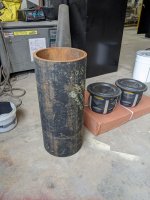
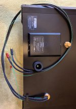
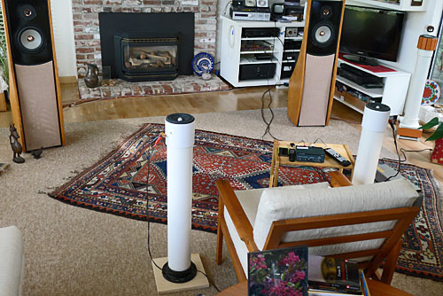
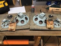
I thought I'd share the dual 10" subwoofer enclosure I'm building for my 2 channel setup at home. It is being build from a 10-3/4" piece of schedule 80 steel pipe, this is because I absolutely hate everything about woodworking and I'm very good at working with steel. I'll be using a pair of Hertz Mille ML2500 drivers I've had kicking around for ages, I'll be powering them with a Behringer EPX2800 pro audio amplifier.

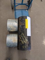
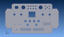
The large tube will be cut to accept the smaller tubes and they will be recessed so they only stick out about an inch. The excess material left on the inside will be cut off after everything is welded. I will be getting steel rings laser cut to mount the drivers to.

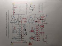
I will post up my blueprints tomorrow to give a better idea of exactly what I'm doing.

pxl_20220228_174350824-jpg.1030148


pxl_20220228_211857612-jpg.1030149

Attachments

  • PXL_20220228_174350824.jpg
    PXL_20220228_174350824.jpg
    590.9 KB · Views: 166
  • PXL_20220228_211857612.jpg
    PXL_20220228_211857612.jpg
    562 KB · Views: 171

For Sale Rega P5 Turntable for Repair or Parts

The problem with the Rega P5 is that the turntable speed does not sound as stable as it should. The RPM iPhone app shows that it runs close to 33RPM, but that the W&F measures 0.4-0.5%. I couldn’t find any published specs. I have decided to get a better turntable instead of chasing this problem and trying upgrades.
I am the original owner and have used the P5 sparingly over the past 10 years.
I also have the OEM box. Cartridge not included. Asking $500 + shipping.

Will sell individual parts if no one interested in the whole unit.
  • RB700 Tonearm with Incognito wiring upgrade
  • TTPSU
  • Glass Platter
  • Plastic cover

Attachments

  • P5 Front.jpg
    P5 Front.jpg
    116.2 KB · Views: 305
  • P5 Bottom.jpg
    P5 Bottom.jpg
    448.1 KB · Views: 342
  • P5 Box.jpg
    P5 Box.jpg
    285.8 KB · Views: 259

Mounting a Grayhill switch in a 10mm faceplate

I purchased an enclosure from the diyAudio store with a 10mm thick faceplate for the Kuartlotron I'm building. I purchased a Grayhill switch for the inputs but I didn't think this through when reviewing the drawing for the switch. The threads on the switch have a flat spot, clearly to stop any rotation of the switch body when selecting.

My plan is to drill a recess into the plate to mount the switch. My thought is to drill through the plate and file/Dremel away the mounting hole to size. I doubt it will be perfect, but taking it slowly, get a decent fit. If anyone know of a better option, let me know, as long as it doesn't involve expensive tooling for one switch installation.

Sony C37 Valve mic question

I'm having a go at building my first valve mic , and looking at various circuits. The Sony C37 appealed because of it's simplicity and offboard output transformer, but there is one aspect that intrigued me - it's a Cathode Follower design but there is no capacitor between the cathode and the output transformer so there is a fairly high DC on the transformer. All of the non CF designs I have seen have a large high voltage capacitor blocking DC from the plate , and all CF designs I see in amps and have used myself have capacitors too. Is there any downside to this ? I'm assuming it doesn't affect sound quality or the mic wouldn't be as revered as it is , but does it change the tolerance of the winding wire used?

Screen Shot 2022-03-02 at 14.17.33.pngScreen Shot 2022-03-02 at 14.17.46.png
  • Like
Reactions: krivium

Oscillations

After so many troubles with making and testing amplifiers with push pull buffers before the feedback point, I have decided to make a document which reflects what I have found.

An attempt has been made to make the document as concise as I can, just a few pages. Of course, the most important part is last.

The document concentrates, only, on simple weapons against oscillations, such as, a Zobel network and resistors. The new finding, which, I cannot find anywhere, is the possibility to eliminate or significantly decrease oscillations without any capacitors an Zobel networks, just, with simple resistors, which provide stable potentials and resistive paths for oscillations. The most important of them is a simple, load resistor in parallel to the speaker with a value of ten fold the value of the resistance of the speaker.

Of course, a combination of a few or all weapons against oscillations is possible.

Here is the document, called " Oscillations.doc " :

https://drive.google.com/drive/folders/1SXkcSbGwEz8DTH_6DdtDwolBuergbvyh

GFA-555 JFET AFE

I have such a great experience modifying my 555 (s) that I can't help but think that a cascode SK170 SJ74's push pull on the front end of this BJT amp would be oh so sweet. I just love my modified hafer jfet amps and want to have the same love for the BJT Adcom amps. I'm not going to go into the weeds here about the engineering details. My hope would be that this community might help to educate me as to why I cannot use a F5T FE to drive an Adcom 555 output stage. I happen to have a surplus of these board so that I can get enough output pcbs to realize 6 pairs. I do realize there is no feedback circuit, but what else am I missing beyond using ohms law to adjust voltages and current ? I suppose I am more keen on understanding these circuits than anything else.... Does the F5t FE rely on the precision output stage so as not to require a feed back circuit? For me, I have to say it seems like Mr. Pass gives enough of the goods inspire the drive to want to learn more. Peace.

what is the difference between linkwitz-riley crossovers and butterworth crossovers

Hi all. do I know what I'm doing? So I looked at schematics of Linkwitz-Riley 3rd order and butterworth 3rd order crossovers for tweeters and they appear to be the same. Is the only difference the values of the caps and inductors? Attached is the schematic of my outboard XO which looks like the schematics for LR and Butterworth I've seen. Then again I may be totally wrong and not understanding the schematics.

3rd order XO.jpg

Recording Software advice??

Hi all. So I am relatively new to bass, but not to music. But I've never tried to seriously record anything. My question to you guys today is about that. I know nothing at all about it and would like to look into building a basic setup. Software, audio peripherals, etc. My end goal is to record tracks into a laptop and do some basic arranging, I can get cash advice online and buy expensive software. Any and all help is appreciated. Thanks!

Amp Blowing Mosfets, Tired of the Guess and Check Method

I have reached the limit of what i know (which is basically 0) and have resorted to randomly de soldering and testing various resistors and transistors in hopes of getting lucky but maybe somebody on here has some extra patience and would be willing to suggest at least a direction?

it's a Rolls RA200 amp and it's blowing all 4 mosfets and fuses. got it used, fuses and mosfets were blown, replaced all powered it on while everything was pulled apart on the bench and they all blew again (within maybe 30 seconds). replaced again and then reassembled with heatsink and this time it worked for about a month then it blew while i was out of the room sending 50v to my speakers taking one out.

At this point i started attempting to trace back on the schematic from the power switch to the mosfets assuming that whatever is failing must be something common to both channels? i've pulled a lot of transistors and other components to test and so far everything tests good.

the last time they blew i had a multimeter on the mosfets, measuring voltage and i noted there was 50v on both the gate and source and 3v on the drain. mosfet started getting warm to the touch and before i could power off they blew. (after they go then the fuse also goes).

hoping somebody might be able to give me a hint, i have attached the schematic below.
rolls.PNG

TCJ Unanticipated Amp with some variants including auto bias and Class-G

The TCJ Unanticipated Amp in Blog 546 17 October 2021 has some pretty interesting ideas such as 1) the singleton input stage that John calls a Bastode (aka Rush pair) instead of a differential input stage that drives a push-pull VAS, and 2) a Class-AB+C output stage (aka DoubleCross).

My simulation, as close as possible to the original, is attached.
TCJ-17102021-unanticipated-amp-Org-cct.png

To get it stable I used shunt compensation (C8, R21) and minimised the feedback resistors shunt capacitor (was 300pF now 56pF). This gives roll-off at 1.5MHz. Clip recovery also looks good with no spike in the d(V(out)) plot (LHS corner). THD is low at 0.047% at full output (+/-24Vpk).
TCJ-17102021-unanticipated-amp-Org-Av.png

An interesting feature of the distortion profile is dominant 2nd harmonic which according to John gives "single-ended-quality sound". This feature appears to be due to the Bastode (Rush) input stage which does not cancel even harmonics like the usual LTP input stage.

The Class-AB+C (DoubleCross) output stage can be seen in action in the plot above. The idle current is quite high at nearly 200mA in Q9 and Q10 and covers the first watt in Class-A. Above 400mA the Class-C transistors Q11 and Q12 conduct and they blend in smoothly with no Gm-doubling effect above 1 watt. Nice.

One down side I noticed is a relatively low slew-rate of 3.3V/us (with compensation that I used). This only allows full output swing to 20kHz before it slew limits. I would prefer more like 100kHz so I tried some things to increase the slew rate. Mods are in following threads. I also tried adding autobias and Class-G.

Attachments

Quad ESL63 Restoration - dustcover frame

Hi,
I am restoring a beat up and messed with late model ESL63. The panels and electronics are fine and I have successfully finished 1 speaker.
However one speaker is missing all the dust cover frame pieces. The rest of the frame is in poor condition. The plastic base where the extruded Aluminium side pieces are screwed in have broken on both sides. The grill cloth is missing.

I will hunt around for hard rubber or plastic "C" section strips and possibly glue them to hard plastic strips to try and recreate the original. I am not sure if I can source the bits locally and if they would hold on firmly enough under tension.

I am hoping someone has found a solution or can think of a suggestion.
Thanks,
Kffern

New kang... 15SQV + AC15D + AP1200 + CX2100

So I decided I want to play with a subwoofer in the house but I didn't like the price/performance of any of the powered subs for home I saw that were affordable for me.

But: I used to put subs in my car, and I have a Yorkville AP1200 sitting around so...

I bought:

https://atrendusa.com/products/15-single-vented
and

https://planetaudio.com/product/ac15d/...
I'm going to use a CX2100 active crossover that's dialable down to 10Hz, and the Yorkville can push almost 1kW into 8R in bridge. I have a small apartment so efficiency isn't important, just low frequency. My main speakers are 31Hz -3db so this will just fill in the bottom for things like explosions in movies or super low notes on some music.

Even including what I paid for the Yorkville, this build cost less than 300$ since I had the crossover.
Thoughts?

Hypex DSP module(s)

Digital audio processing is slowly coming to the modern DIYers. Whenever someone plans to build a preamp, an active speaker system or a multichannel room setup, DSPs are an alternative to the well established (and widely accepted) active or passive crossovers using RC-filters.

The goal of this thread is to summarize the possibilities (and possible deficiencies) of current and future DSP products and developments of Hypex Electronics B.V. from Groningen in the Netherlands. Other manufacturers' products, such as the Mini DSP line by DSP4YOU Ltd., are already covered in some other threads.

Current DSP-based Hypex products (as of this writing) are the AS2.100 (Digital) and the (still preliminary) PSC2.400 (for the more professionally minded).

A standalone DSP board was anounced a while ago. Matthijs Oskam (of Hypex) made a comment about it's development over here:

Matthijs_Hypex said:
We restarted the development of the 6-channel (DLCP) last month and have one person working on it full time. We are also looking for the most flexible setup for this board

So, currently no separate DSP unit is available form Hypex, yet the platform seems to work well, as users of the aforementioned AS2.100 acknowledge.

What's everyone's requirement in an integrated module?
What's everyone's requirement in a separate DSP unit.

Cheers,
Sebastian.

Compact PA-sub ideas with 12-280/8-W

Hi Guys.

I´ve looked at this kind of problem before and (spoiler alert) for at compact PA-sub nothing beats a standard bas-refleks.
- at least when the only design-goals are output, freg.-range, size and complexity.

BUT, lets say that other factors are included in the design-requirement: Cooling of driver and amp-module and "novelty". For the design at hand the power is limited and thus cooling is maybe an mental-exercise, but the considerations should be valid for other designs as well. (Maybe I´m just bored with standard design).

Design-goals:
  • Driver: 12-280/W-8 (Thomann link: https://www.thomann.de/dk/the_box_speaker_12_280_8_w.htm )
    • Got the driver already
  • Cabinet-size max 50-60Liter internal ( including, braces, dividers, ports, ect)
    • Storage-space is limited and use-case is portable in small car to "venue"
  • Freq-range: 50Hz(-3dB) minimum, better 45Hz. 180Hz upper limit.
    • I've analyzed quite a few relevant music-tracks in Audacity and primary bass is centered at 50-60Hz. Information at 40Hz is often 3-10dB down.
  • Active driven. 200-400W available. active filters. simple electronic EQ and notch acceptable.
    • DIY classD, LCC-supply, analog peak and RMS-limiter
  • Somewhere between Hifi-and PA-sound.
  • Sensitivity between 90 and 95dB
  • "PA" as in party-music and robust, not stadium, Drum´n´bass and 1000 people 🙂
  • I can accept some distortion at high levels, but not physical driver-damage.
Horn-resp ideas for different designs will follow.

Please comment and suggest.

Kind regards Troels

Driver-1.PNG

Attachments

FS 'Riegstra' MM phono amplifier DIY project

FS For Sale - 'Riegstra' MM phono amplifier DIY project.

Unfinished project. Please check photos. This is the so-called 'Riegstra' design as published in Elektor and AudioXpress. Advantage of the circuit is that small and even 'loud' clicks are 'eliminated' by the first opamp circuitry, the clicks are less noticeable. Riegstra from the Netherlands build this circuitry and found out by coincidence the specialty of this circuit.

In fact two cheap standard 'Audiowind' stereo MM boards are used for the project, these boards are transferred to mono, this to fit the 'Riegstra' circuitry.

Included:
1. 2x MM mono boards
2. 1x power supply board, discrete design, low-noise, if I am correct this is the 'STAX' design (as can be bought on Ebay).
3. 'double opamp' PCB to single opamp use.
4. box with parts, including Vishay 128 SAL-RPM as coupling caps (very close to Black Gate).
5. aluminium case.
6. separate AC power supply using power transformer, including connector (black plastic box in photo).
7. transport box.
8. all documentation in PDF format (very well documented).
9. included 4x AD845 opamps (not clear if these can be used in this circuitry). Any opamp like a single opamp as the NE5534, OPA134 and for example OPA627 can be used (4 single opamps are needed to make the project work).
10. project to be finished by you, no help or support is guaranteed, it is you to make it up and running.

Price unknown, but will make it interesting for you. You may send your price idea on this.

Attachments

  • IMG_20220302_201913313.jpg
    IMG_20220302_201913313.jpg
    304.3 KB · Views: 127
  • IMG_20220302_201940392.jpg
    IMG_20220302_201940392.jpg
    302.1 KB · Views: 107
  • IMG_20220302_202005099.jpg
    IMG_20220302_202005099.jpg
    245.9 KB · Views: 109
  • IMG_20220302_202035243.jpg
    IMG_20220302_202035243.jpg
    202.5 KB · Views: 122
  • IMG_20220302_202102623.jpg
    IMG_20220302_202102623.jpg
    345 KB · Views: 116
  • IMG_20220302_202113784.jpg
    IMG_20220302_202113784.jpg
    319.4 KB · Views: 121
  • IMG_20220302_202140726.jpg
    IMG_20220302_202140726.jpg
    466.6 KB · Views: 113
  • IMG_20220302_202140933.jpg
    IMG_20220302_202140933.jpg
    481.5 KB · Views: 117
  • IMG_20220302_202147831.jpg
    IMG_20220302_202147831.jpg
    417.3 KB · Views: 121
  • IMG_20220302_204249638.jpg
    IMG_20220302_204249638.jpg
    286.6 KB · Views: 122

Taramps smart 3 behavior?

I am running 5 jl audio 8w1v2 single 4 ohm woofers for a total 0.8ohm load.

The electrical system is a 240a alternator, one stock battery and one 14ft run of 4ga ofc to a fused distribution block. The distribution block supplies a taramps smart 3 and a jl audio e6450.

Before running the smart 3 I had a RE audio usx65.1kv, then a US amps Merlin MD3D which is nearly identical to the RE amp.

The issue I have is the Taramps goes into low voltage protection (two flashes of the red led) when turned up but significantly below clipping.

Using the min/max function on a Fluke multimeter, the lowest voltage measured at the amp input terminals during a shutdown incident was 12.54 volts.

My question is: Is the smart 3 so smart the 0.8ohm load is shutting it down? Or will these amps shut down if the voltage briefly dips below 12v?(which could be happening and my meter may not be quick enough to see it.)

I have not been able to drive the smart 3 anywhere near the power level of the previous two amps. Neither of the previous two amps ever shut down or went into protect ever even after long periods of abuse.

This is the first time I’ve ever seen a taramps in person, therefore, have no experience with them until this week. Any input from those experienced with taramps is greatly appreciated!

Any experience with these (cheap) Chinese prefab Bluetooth/FM/MP3 modules?

Hi, I was investigating building my own low-budget boombox with prefab FM and class D amp boards (and was worried about poperly combining them in away to avoid RF/EM interference), but I see that these (cheap) prefab integrated multi-function units are available on eBay, partsexpress, etc.

There are many variants built with the same basic LED control panel (actually, there are two out there: one is rectangular, and one is oval). Some have only preamp outputs, while others are advertised with 3 watts amps and others are up to 15-25 watts per channel (hah). I see that those have various sized PC boards attached to the base unit, all pesumably using their own circuitry/amp choices. But none of the pics is clear enoughto see, for example, which amp chipset is used. Some show some possible filter caps onboard.

There are reviews online, including on Youtube, but unfortunately, they mostly don't give enough detail about which "variant" or amp chip/circuit is used. Amazon reviews are all over the map (not suurpisingly). Several are not in English, so I can't understand them. This one shows a few variants: Login to view embedded media
Does anyone have experience with these and can recommend the betterversion/supplier? I am mostly interested in whether or not they have adequate FM broadcast radio gain/reception with minimal EM/RF Interference.

https://cntronic.com/car-12v-color-...ecoder-board-module-audio-refitting-71409skn1https://www.parts-express.com/Bluetooth-5.0-FM-Media-Player-2-x-25W-Max-Amplifier-Board-320-642https://www.ebay.com/itm/-/175055546593https://www.ebay.com/itm/-/373858239053https://www.amazon.com/dp/B07SN1PFYC/ref=cm_sw_em_r_mt_dp_VWDW1KHT79A7QD8C0JHRttps://www.ebay.com/itm/-/115210604729


Thanks!
Lou

Attachments

  • s-l1600-10.jpg
    s-l1600-10.jpg
    120.8 KB · Views: 136
  • s-l1600-9.jpg
    s-l1600-9.jpg
    101 KB · Views: 134

where would the ground on a mobility scooter/gopher be?

The inbuilt battery charger let go of the magic smoke so I threw it out because it was beyond economic repair. There are three wires for the new portable charger to plug into, Red positive, Black negative and Green ground, I've got the Red and Black sorted but I was wondering where the ground would be, would it be the chassis? I don't want to risk frying any of the microprocessors on this thing by experimenting. Any help will be appreciated.

Diaphragm heat treatment

I read somewhere that Quad performs a heat treatment after tensioning the diaphragm to 'set' the film.
I am curious if anybody has a clue or good guess as to what perpose this serves. I mean what are the effects on the performance of a panel? Does the tension hold longer? I'm also wondering how one would deduce the obvious parameters like temperature and duration of the heating.

Thanks for any insight into this process!

Arend-Jan

Idler wheel repair options QRK 12C

Hi,

I have a QRK 12C turntable in great condition, but the idler wheel as a little indent probably due to the idler resting on the motor spindle.
The rubber is in OK condition and I found information on how to restore the rubber using different methods, including rubber rejuvenator products.
What are my DIY options? I found some replacement alternatives but they will cost me between $150 to $200 Canadian dollars.
  1. Can I sand the wheel? If yes, before rejuvenating or after?
  2. Can I machine the rubber to remove a layer and then put a rectangular o-ring around? Do I freeze the rubber before attempting this?
  3. Other options?
Here's a picture of the idler wheel
idler.jpg


Francesco

Neurochrome preamp - options, ideas, tips?

Hello Forum,

Last year I built a modulus-86 from Neurochrome. It was a great project and @tomchr was very helpful, enabling a person like me without a lot of electronics knowledge to build a working amp.
I didn't have a proper preamp to run the mod-86 with, only a cheap mini bluetooth input selector and volume control. None of my other amps have outputs for an external power amp. Problem: it doesn't get very loud. But I guess I can change this by allowing more gain either via the resistors on the modulus boards or with a universal buffer. First imression was still good, it sounded more precise than before with an old NAD 3020e. The big disappointment came when I compared it with a 1992 Creek 4040s3. The modulus with the chinese preamp sounded -surprise- awful in comparison. I expected it to be worse than the Creek but it was no match at all. The creek is to this day the best amp I ever owned, the "size of the room", the location of the instruments and the warmth of the sound are just fantastic.
So of course the next step would be a diy preamp, preferrably from Tom. I ordered the input selector and the preamp psu to start with and want to add one of his universal buffers to provide a balanced connection to the power amp. Got the parts from mouser and assembled the input selector, switch and volume control.

So I started planning an enclosure and realised that the psu, volume control, input selector and buffer fit into a really small box. Now I wonder if it would make sense to build one enclosure for both, preamp and modulus. The advantage would be that I have to buy fewer connectors if I can wire it internally instead. I could also add an arduino for the remote contol, stepper motors for volume, a hifiberry dac and a display in the same box.

A few questions about the wiring:
What kind of cable would be best to connect the RCA sockets to the input selector? The RCA sockets to solder straight onto the boards are all totally unshielded. I assume I want to keep the wires as short as possible?
Is the length of the ribbon cable for the volume control a problem? If it is a problem I'll get the volume pot near the input selector and connect it with a long rod to the volume knob. Otherwise the volume knob goes into the front, I guess that would make the assembly easier.

Although I've seen quite a few now, please share pictures of your (Neurochrome) preamp designs, just to get more ideas.

Thanks for your time
Stefan

Massdrop Airist discrete R2R DAC controversy

JB7clo6kQj2lUW9y9iir_AI7B7978%20copy_new.jpg

wmqAg9BSQxOuGDadwNlz_airistinterior%20copy.jpg


This orig $350.00 USD of this DAC was low enough for it to be sold out quickly on Massdrop.
The forum discussion on Massdrop is huge (2-3k responses), and there is controversy on how "original" this design is.
Of relevance to the DIYA community is the comparison to the Soekris DAC. Charges of intellectual property theft have been slung in multiple directions.
I've seen Soekris here at DIYA for years, but the Airist is relative newcomer.
That said, discrete R2R topology has been around for decades.
So what is the source for the orig. Airist R2R DAC design?


REFS:
Drop: Passions lead here (formerly Massdrop)
RDAC Drama: Allegations of Airist Audio and Massdrop copying DIY work. Details in comments. : headphones

============

Gzh6-HM55-Ecke56-B5s6c-NSp-Svy-U5-Hm-Inz97-e-DJ-Pm-Uo.jpg

Help on connecting 2 device through I2S on ADAU1701

I'm planning to build an audio mixer using Wondom ADAU1701 and I want to get an audio signal from multiple devices from I2S, one ADC converter which are CS5343 (I need to give extra since the ADAU1701 DSP only have 2 ADC). The other audio signal is from HDMI converter which I use WM8804 to get I2S at the end. However, the CS5343 & WM8804 will give 2 signal of I2S to my ADAU1701 which confuse me, and not sure how to combine them. I see through the internet that we can get multiple I2S device data but only need to make sure they have the same clock, is this right? Or is there another way?

Can I use a teleporter to feed DSD and PCM to the BIIIse pro?

I'm building a new BIII pro se 9028 and would like to feed I2s directly to it with a teleporter. I want to use a denafrips Iris to send the I2s from my PC to the DAC.

https://www.denafrips.com/iris
I have both DSD and PCM files and will be using DimDim's isolator and Arduino control code to control the BIII so it will allow PCM and DSD to switch one the fly. My question is can the teleporter receive both signals and send it to the DAC without changing the connection or is it one or the other and not both?

Remote losing power real fast

Hi
I got a Yamaha RX-V2400 remote that when I put in new batteries, works a while, then stops working, after a a day or so, when I check batteries they are near empty, The remote is not sending out signal, checked with phone camera and also the emitter light stays off, so no sticking of remotepads causing this, there is one cap I have not replaced yet, a 220 µF 6,3 volts, can this, when bad, cause this problem?
Cheers, Tojoko.

I feel hitting "register" could be a watershed moment.

I hit that button though, so here I am!

I used to be in to HiFi as a teen, that lead me in to pro-audio field of education.

After that (music tech, for the gear more then making music) I have worked mostly in AV, but had a good stint in a London based Mastering Studio (Restoring the audio for CD re-issue using a Cedar Cambridge)

Having FINALLY moved in to a house where I can make as much noise as I want (owning your 4th wall outright is expensive, but we got here)... I'm being drawn back in to HiFi.

I've already bought a Marantz CD273 (A seemingly forgotten TDA1541a model that shares it's CDM and PCB with higher models such as the Philips CD650, probably doesn't help it looks EXACTLY like a CD45).. but this is due to be replaced, any day now, with a Marantz CD65 (mk1).

Yes.. they do have the same internal parts. I'm not convinced the 273 is healthy, so between the two players some modding and repairing will now occur and I'll hopfully end up with the CD player I hope too.

Looking forward to contributing 🙂
Rob.

That's What She Said RH84 Build Log

"That is WAY too small!"

"Where do you think you're sticking that??"

"Wow, nice wood."

With an extra 120V secondary power transformer from Antek (w/ 2 x 6.3V heaters @ 2A) , some 6BQ5's and 12AT7s from my stash of tubes, and a few feet of nice walnut left over from another project, I've embarked on an extremely small footprint RH84 build. The top plate on the chassis measures 6" x 10". Because of the small size of the chassis (and the 120V secondary), this will use a voltage doubler to achieve 300V B+ (see this thread where I talked about the PSU).

Here's a layout picture now that I've received all my parts:


The walnut is 1/2" thick mitered at the corners and the top plate is 1/8" aluminum. I used small blocks at the corners to support the top plate and to reinforce the miters. The bolt near the front left is for the toroid under the deck, the choke (back left) is a Hammond, and the OPTs are 5W Transcendars (I'm very excited to use these).

All holes are drilled and the switch/IEC/fuse is mounted (upper right of this pic):


As you can see, this is a tight fit (that's what she said!). I'll mount the voltage doubler 'module' (built on a terminal strip) just behind the power transformer. I'm still working on the best place to fit the filter caps (2 x 220uf, rather large). Anyone have practical advice on placement of these with regards to the OPTs or tube sockets? I'm thinking 'between' the OPTs on the underside to give me as short as possible B+ runs after the filtering.

Finally, here we are with everything test fit:


I'm thinking inputs on the front right of the top plate and volume control on the right side of the front walnut 'apron'.

So far, so good. I'm a bit worried about how tight the power supply is, but you know what they say about good things in small packages (that's what she said!).

Marantz 7T preamp power up?

Hi,

Some days…are wonderful 🙂

I was just gifted a Marantz 7T pre amp.

I have no idea how long this has been sitting, but it’s been at least 2 years. It looks to be all original inside, and is in like new condition in there. So clean!

Now, I don’t have a varistor. Any thoughts on how to go about turning it on safely? I have a dim bulb tester and a light dimmer wired into a short extension cord.

Any thoughts would be greatly appreciated.

Thanks!

P

1E31B4E4-57BF-448D-9532-F9D07E9CE935.jpeg
44F1D9F6-48D3-4B9B-AA25-A7DAB84E5E21.jpeg

GB query interest for RemoteDial

Hi,

I finished a new project RemoteDial.
It is a Infrared Remote Control with following features:

- very compact
- min. amount of parts
- teach mode (learnable) for most IR protocols
- 6 functions only with one push button rotary encoder
(for example Volume -, Volume +, Input -, Input +, Mute, Standby)
- run with a CR2032 battery or alternative (AA or AAA)
- qiescent current 3-9uA
- battery life >30 month

Actually we build some Dials in a german forum.

Is someone interested?
In this case I will start a new batch pcbs and I will translate the documentation.

Attachments

  • 7240E519-F7A4-4435-90C4-AF0A6516F54A.jpeg
    7240E519-F7A4-4435-90C4-AF0A6516F54A.jpeg
    66.5 KB · Views: 883
  • 88B1B276-80B1-4382-80B8-F09688D66C4D.jpeg
    88B1B276-80B1-4382-80B8-F09688D66C4D.jpeg
    55.9 KB · Views: 937
  • E85ECFD1-C6CD-4DC4-8505-BA1BE673CFFE.jpeg
    E85ECFD1-C6CD-4DC4-8505-BA1BE673CFFE.jpeg
    59.9 KB · Views: 901

Onkyo CR-L5 standby trouble

Hello again!

I'm having trouble with an onkyo cr-l5 that doesn't come out of standby. There was a leaking supercap that I already replaced without any change. If anyone has it or fixed one of these with the same problem that would be very helpful. I tried forcing the power relay to close by shorting one pin to ground (with a dim bulb tester), the amp comes on (dim bulb flashes and turns almost off) but the standby light stays on and the display doesn't come on, no commands work and there's no sound. I'm guessing like the Onkyo cr-305 thread there is something wrong with the standby power supply but without schematic it's really hard to troubleshoot. I do have +5.6V and +10.6V coming from the board with the little standby power supply.

Doubler PS sanity check

Good day,
I have some 120VAC transformers I would like to put to good use. I need about +260V at circa 140mA, and -260V at circa 20mA. Doubling the 120VAC will do the job easily, but is it possible to also extract the -260V from it? One solution I came up with is shown in the schematic (done in multisim) + simulated output. C1 and C2 are 200V caps, C3...C6 are 450V.

what do you think? Any suggestions for improvements?

many thanks,
Erik

Attachments

  • DoublerSupply.jpg
    DoublerSupply.jpg
    117.4 KB · Views: 134

DIY network streamer and internet radio

Hey everyone,

I've been wanting a NAS streamer (renderer 🙄) and internet radio for a while.
The 'problem' seems to be I already own a good amplifier with a perfectly serviceable AK4490QM DAC. I have no requirement for a streamer wit a built in DAC.

Also, I find streamers a very bad investment : the technology advances so quickly your few thousand USD/EUR/UKP investment in a high end unit will be worthless a few months from now since it's old hat.

So I started with a Pi, tried, Moode (edit : not Roon, I'm an idiot) and now I'm testing Volumio. I've tried several PC hardware based solutions, like Audirvana, JRiver and a few others, but I find them inefficient and mostly clumsy. I like the Pi thing.

Now I want to start upgrading the Pi setup. I've bought the IanCanada Station Pi and the Dual Linear Pi, and a nice toroid. This I will assemble first. It should be pretty much plug and play for the existing Volumio Pi.

I just can't seem to figure out what the next step would be. I think it would be cleaning up the PI USB with some kind of isolator ? I've seen the Ian Canada one, but it looks a tad expensive.
Are there cheaper alternatives you could recommend ? I would like to stick with the USB, as it offers the fastest datarate (384 kHz), and I use the coax and optical inputs on the dac for other things.

What would you recommend ? I'm staying away from supercaps and batteries for now.

Thanks, Pete

Clear sale

I would like to clear diy pcb board
1: 5 PCs of power filter $70
2: firstwatt f3 $15
3 : power supply total 8 PCs $50
4 : aleph p pcb and match IC $30
5 ; TAsa v4 3 Chanel 1 Chanel good condition
And two are need to service come with power supply boards $150?
6:Ryan Tda1541 dac v3 $20
7: ssr03 power board $30
All are not including shipping
Ship from Asia

Alpeh J complete board

Hello ,
I would like to sell my alpeh J stero complete board only .
left channel is no basic and no sound you need to service .
Right Chanel all perfect .
chassis is also not included and but if you afford shipping coast I can let go .
Alpeh j module stero price $150 + shipping.

best regards

Attachments

  • 6632C251-8E7B-48A6-8659-753A84B0C40B.jpeg
    6632C251-8E7B-48A6-8659-753A84B0C40B.jpeg
    367.9 KB · Views: 155
  • 856C4572-4167-46B8-94DF-AF959C49CF5D.jpeg
    856C4572-4167-46B8-94DF-AF959C49CF5D.jpeg
    453.2 KB · Views: 162
  • B4E7C9A9-FB67-4AAE-8A5D-93DE195A90DC.jpeg
    B4E7C9A9-FB67-4AAE-8A5D-93DE195A90DC.jpeg
    443.4 KB · Views: 159

Custom chassis design & manufacture sources?

Outgrew original ChiFi chassis- added outboard project box to house some SS front end features... EQ, DAC, BT and phono preamp. Looks ok way it is- but that's not how hobbies work- lol. Just finished CAD layout of new chassis and began sourcing metal- 20ga 304 SS, and fabricators.
Have used Xometry and 3D hubs for 5 axis cnc of 1018 steel and 6061 AL stuff in previous automotive perf projects, but not sheet metal. When 2D design below was submitted, 3D hubs online quote tool showed $153 + the ride. I thought that seemed high- idk.

Lil more searching I found couple raw mat'l sources... but still need fab cut source if piecemeal it out.

https://www.speedymetals.com/pc-1613-8280-20ga-0035-304-stainless-steel-sheet-4-finish.aspxhttps://www.ebay.com/itm/233297812591?hash=item3651a21c6f:g:DR0AAOSwHb9ZcM0~
Did quick search diyaudio, but didn't see any other forum threads for fab sources, methods, software used...
So thought this thread might shed some sources here and across the pond.

Jim

Attachments

  • Tube chassis.jpg
    Tube chassis.jpg
    78.7 KB · Views: 172

DavidLouis VX8 wide band

After going through some 7 or 8 wide bands,, I finally hit on the speaker I feel is the wide band to beat.
I madea series of YT vids, you can hear everything I have to say about the perf of this speaker.
Some tech geek in china knows how to build a very musical high fidelity speaker.

I had the Voxativ AC1A, has a series of **pill* style neodymium magnets,, = what a piece of ______, Fill in the blank.
Lost $900+ on that *thing*,
paper cone = thin paper, zero bass, mids PUKEEE, no highs , sensitivity , at best 82db.

This DavidLouis will put the AER to the shootout,,and perhaps come out top dawg gun slinger

cabinet 30 inch X 10 inch X 10 inch = 50 liters, 2 inch thick attic glass fiber insulation stretched along back top and bottom.
Bass 10/10
Midrange 10/10
Highs 9/10.


DavidLouis VX8, Perfection - YouTube

Counterpoint SA-100 with Exicon MOSFETs

Hi,

I don't often plead for help, but I've got a Counterpoint SA-100 with a blown channel that's been sitting around for a few years. I finally decided to get it up and running again and purchased a full compliment of Exicon 20N16 and 20P16 to replace the CPT10N12 & 10P12.

I don't know why, but I seem to have damaged the Exicons between the gate and sources - both the N & P types.

I did this only on one channel because the other channel had a working set of the original MOSFETs. Just for a sanity check, I insalled a working set of devices from a Counterpoint SA-220 (RFM 10N15 and IRFP 9241) in the blown channel and it works fine - so I know for sure both channels work and that the issue is with the MOSFETS.

I thought that by slowly bringing the amp up on a variac wold keep me from damaging the Exicons in case there were some bias voltage problems. I brought the rails only up to +/- 10V or so. The gate voltage went up to around 1.5V on the N side, and suddenly went way down. I noticed this morning that the 1A safety fuse I installed in the rail was blown, so I replaced it. The other rail fuse had a 1ohm resistor so I could monitor current. I just cracked the variac open (for 300mv at rails) after replacing the fuse and now the devices are drawing as much current as they can - this means a short somewhere. I measured the N and P MOSFETs with the diode tester and I'm getting strange numbers.

What did I do wrong? Am I mis-handling the Mosfets somehow? I'm totally not MOSFET savvy so it may be something really rudimentary that I neglected to do. I have one more channels worth of Exicons, but I don't want to destroy these too.

I know Chris might say that I'm abusing good MOSFETS by installing them in a Counterpoint, but I really just want this to work without having to re-engineer it, and the Exicons were (I thought) the easiest way to get it to work.

Thanks for your help,

Assorted Pulsed transistor measurements

I've build a setup to do various kinds of measurements on transistors and amplifier output stages. In its current incarnation, the business end of it looks like this:

testjig simplified schema.jpg

It has two states:

At idle, M1 M2 M3 are off, Q1 sets the Vce (or Vds) of the transistor under test (DUT), and it is biased with a 12mA CCS. A MCP9701A temperature probe soldered on a piece of copper sheet clamped on the back of the power transistor measures temperature.

To do a pulsed measurement, first the programmable positive and negative power supplies are set to the desired value ; the positive one sets Vce, and the negative one sets pulse current. Then M3 turns on, which applies Vce ; M1 or M2 turn on, which applies current to the transistor ; a few microseconds later, the microcontroller's ADC measures base current, Vbe, and the voltage on the emitter. Then it turns off the FETs, which returns everything to idle, waits a bit, and resumes stepping through the set values of voltage and current.

Temperature is stepped too: before the test is started, the transistor heats itself to 100°C using the same FET-switched current setting resistors as during the measurement. The transistor and temperature probe are wrapped in a bunch of paper towels, so the assembly slowly cools down to ambient temperature over a period of several minutes.

I'll spare you the rest of the details on the implementation.

First experiment is an IRFP240. Instead of a short pulsed measurement yielding one data point (as explained above) here a 20W heating pulse is applied during about one second, during which Vgs is recorded.

IRFP240 thermal interface materials.png

This is pretty much the same as the transient thermal impedance. Junction temperature can be extracted from Vgs with a tempco of about 4-5mV/°C so here, it doesn't heat that much. 20W for 20ms results in about 1°C heating. It is linear with applied power.

"IRFP240" means just the naked transistor. Then it is attached to a small aluminium heatsink with various materials. The generic fiberglass loaded silicone silpad is absolute garbage, its thermal conductivity is only 2W/mK, which results in a transient response that isn't different from no heatsink at all. The transistor would have to heat until there is enough of a delta-T to have proper heat transfer. On the other hand, both the grease and the GELID GP-ULTIMATE (a thermal pad for discriminating overclockers) work extremely well.

In other words, the available one-second Safe Operating Area of the transistor would be a lot worse with the silpad. I like amplifiers that don't burst into flames, so SOA is important.

However the GELID pads are single use and fall into pieces when removing the transistor, so not really user-friendly. The keratherm pads on the webshop look like a good investment.

Another longer test, grease vs silpad:

IRFP240 thermal interface materials 3s.png

I will test the effects of that on bias stability later...

To be continued.

OTL Topologies

In class A the P-P tube rp curvatures would largely cancel out, but in the class B portions (of class AB operation), the rp curvatures make for odd harmonics.

With the difference in gain between top and bottom banks, the gain also sweeps from low to high as the output current polarity and magnitude changes, causing 2nd harmonic too. It doesn't just "average out". Might be a good idea to add a toggle switch to allow flipping between MP mode and balanced Futterman mode drives. Have it both ways, the listener can decide.

N Fdbk to the rescue for OTL.

The B+ transformer is listed as an isolation xfmr. Usually those have a boost in their turns ratio to preserve output V at max. load (compensating for internal resistance). Since this unit seems to be generating +-150V instead of +-170V I'm guessing the isolation xfmr is installed "backwards" to get a V reduction already. But if not, then that would be an option for compensating for todays higher line voltages. (or a small auto-xfmr reducer) I would guess the power supply xfmr is around 90% efficient, plus some bleeder resistors on the caps.

13/15FM7 tubes appear to have 12B4 guts in them for section #2. These however have a 10 Watt rating and 175 mA peak rating versus the 12B4's 5.5 Watts and 105 mA peak. These used to be on the various $1 lists, but no longer. Could be cheaper to purchase in quantity than 12B4, but 15FM7 are Compactron based.

If someone were going to build another OTL from scratch, I would suggest the 38HE7 tube which is still on the $1 list at ESRC. This is a compactron pentode with 800 mA peak and about 15 Watts Pdiss approx., when operated without the damper diode in the same bottle. (pins 12 and 10 allow operation of just the pentode at 21V and 0.45 A heater, an available option on about 80% of the 38HE7 tubes I've seen) This is 3 times more efficient for peak cathode current versus heater power compared to the 12B4. It is capable of low saturation voltage in pentode configuration, and also has excellent triode curves. But has a low grid 2 V rating (150V).

Two of them in parallel are equivalent to a 42KN6 tube (it is half of the early twin pentode _KN6 version). Which is very close to a 6LX6 tube (which is what is in the later single section 42KN6 tubes). (this is a premium tube, like 6LF6) You'll only need like 3 or 4 of 38HE7 to equal the 30 pieces of 12B4. $4 + sockets.

Stereo Console Speaker repurpose - Part II or I got more speakers - Hah

Well I came up with these, I actually forgot I had them. So I guess to carry over from my last post, https://www.diyaudio.com/community/threads/motorola-stereo-console-speaker-repurpose.383101/ build a box maybe to the rough dimensions of the pictured speaker board, 18.5X11, depth??? and maybe use a pegboard back and stuff and unstuff with polyfiber(?) till it sounds absolutely fantastic. (LMAO)

BL

Attachments

  • IMG_1690.jpg
    IMG_1690.jpg
    104.2 KB · Views: 127

  • Poll Poll
Poll: 8" woofer for a small, closed box with DSP to cover 70-200 Hz.

8" woofer with outer diameter below 226 mm (this excluses most SBA woofers), to play in closed, ~13l

  • Scan Speak 22W4534

    Votes: 3 25.0%
  • Dayton RS225P-4A

    Votes: 4 33.3%
  • Seas CD22RN4X

    Votes: 0 0.0%
  • Peerless 8" SLS - in an open baffle :)

    Votes: 1 8.3%
  • SB Accoustic SB20PFC30

    Votes: 1 8.3%
  • Other - please post Your recommendations.

    Votes: 3 25.0%

I'm looking for options among 8" woofers, for a 3 small 3 way assisted by sub. The cabinet is around 13 litres net, which gives me sealed f3 between 60 and 80 Hz from the drivers listed in poll. Upper range will be around 200-250, where Satori MW13 takes over. This setup will be powere by a Hypex plate amp (50 clean watts into 8 ohm/100 in 4 ohm), so Linkwitz Transform is an option. I aim at peaks reaching 90dB at the listening position, which is about 2,8m away from the speaker.

This project was originally meant as a 2 way, with 5" midwoofer going all the way to 80 hz ina vented cab. When I realised how much time and effort it costs me to finish this, I switched my priorities and decided that 5" based two way will be too much of a compromise and I want to relieve the mid from the hardest work below 200-250 Hz, which is as high as driver spacing allows to stay within 1/4 of XO wavelenght. So I'm adding a woofer to an ongoing build, which means I have to fit the drivers to the enclosure and not the other way around. This means that I have pretty limited space (ita around 16,5 litre but the Hypex plate needs its own subenclosure which will take some space), and limited baffle width - which is 226 mm. This throws SB23 Norex or Alu woofers out of the window with their largest-in-class flanges.

Initially I planned to use RS225P-4A as a widely recommended go-to 8" woofer with low distortion. Unfortunately, then I started reading about Qms and Rms, on which aspects Dayton looks surprisingly poor compared to rivals from Seas, Scan Speak or SBA.

As this will be an active design I can add some EQ to overcome highish F3 but theres also the problem of Q. Of those listed, only Seas will manage a Butterworth 0.707 alignment without EQ, not to mention that it would be nice to also try more damped alignments. RS225 should also manage if I stuff the box a lot, same with SB20. Most other 8" woofers will need some EQ to get to 0.7 Qb and even more for 0.6 or 0.5.

Even though all of listed drivers are pretty popular, theres little info comparing them.
As mentioned, Dayton fares the worst on Qms and Rms terms but poeple seem to be quite happy with it. It also seems like it has the lowest THD between 50 and 200Hz.
Seas fits the bill on paper but its an old design amd I cannot find any THD measuremenets, even though it was used in one of Troels Gravensen designs probably makes it a safe bet. Its also the most expensive of the lot 🙂
Scan Speak looks like the the best pick (higher Qms and lower Rms than Dayton and Seas), has overall low distortion and wide band if I wanted to utilise it in a future 2 way but its not really happy in small boxes. 8" Scan Revelator would fit the bill but its way out of the price range.
SB20PFC has some surpisingly good THD figures, highest Qms and lowest Rms, of the bunch, all despite a plastic basket and at less than 50% of the price of Daytons. Looks good on paper but its cheap so its not really popular on builds that are not super budget oriented.
I also looked at Peerless as I have an 10" XLS sub but HDS 8" woofer has highish 4th harmonic and seems like its happier with lower midrange than bass below 100 Hz. There's also an 8" SLS but at Qts of above 0.6 I could only use it in an open baffle, although I didn't check if I have enough power to do that.

Maybe there's some gem that doesnt cost more than Scan Discovery or Seas Prestige that would make my system happy? What would be Your pick?

Bypassing active crossover of a speaker

Hi, I tried to design my own speaker from scratch and i want to add some features to my speaker such as low power mode. A short description of the speaker is here: the speaker has two drivers - a woofer and a tweeter. The signal passed into the speaker goes through an equaliser, an active crossover, the amplification stage, and then the drivers.
Here is my question. So, in low power mode, I am thinking that the signal will be fed straight to the amplification stage for the tweeter (bypassing the crossover and also switch off the woofer) to save the power used by the woofer. To do this, could I simply connect a switch spanning across crossover to short it out when low power mode is used? Will there be issues caused by this approach?

I want to make my own headset microphone

I was using this setup which worked really well until that cheap little microphone died.

IMG_20201025_003622.jpg


It is plugged into a cheap Ugreen USB sound card.

Instead of buying another one of these microphones, I would like to buy a capsule and make the microphone myself to improve the overall quality. I need help figuring out what I can get away with with regard to the specs of the capsule.

How much voltage can I assume that a USB sound card like this will provide to the microphone and how much does that matter with regard to where it lands in the operating range of a capsule? Would I be better off using, say, a 10mm capsule with a 1v-5v operating range or can I get away with something like a 15mm capsule with a 1v-10v operating range? Will it affect the volume or does the USB sound card compensate for that?

Thank you for your advice.

FS: UGS Muses preamplfier from round 2.

For sale is my UGS Muses preamplifier kit I bought a few months ago. I am building another preamplifier, so therefore, freeing up this one to anyone who might be interested in building this amplifier.

Kit include:
UGS Muses main boards.
UGS Muses Main Power supply V2
Custom Salas Shunt Regulator.

Asking price is €165 + shipping. (same as I paid incl. VAT)

Attachments

  • 20201208_173428_2.jpg
    20201208_173428_2.jpg
    987.4 KB · Views: 352

Driver for a .23cf Sealed box

I’d like to build a sealed box FR speaker with the best mid-range I can get. I’m likely using Parts Express’ Denovo .23cf kit for simplicity. The box’s front baffle is rounded over, so the maximum driver outside diameter is about 6.5” (165mm). I’m leaving the bass to a sub, and after a recent hearing test showed a big falloff over 8K Hz, I’m not going to worry too much about that, either. The amplification is 15-watt Pass ACÁ monoblocs, and the room is 20x20 with hard surfaces. What I want from the speakers is that same pure sweetness that low-power Class A offers. Recommendations gratefully requested, and thanks.

Class A amp with dual Linear supply

Hello DIY world...
Im genrose...
i have an idea id like us to explore if we can make it work...
Diving right in.. In my opinion, class A is superior, especially for transistors.
So Class A to accommodate that dreaded cross over region and speaker control/damping but also have the prodigious output power of class AB?
This is my take... (see diagram)
Ideally as it becomes more developed one could lower that secondary voltage even more to within perhaps a volt or two above signal level..
In the very long run class A with variable proportional switching supply tracking is the ideal i think (something for another thread all together)
I welcome all with any contribution, ideas, criticism etc..
I am humbled to share my idea with such brilliant minds

Attachments

  • Ashampoo_Snap_2022.02.24_12h03m58s_004_.png
    Ashampoo_Snap_2022.02.24_12h03m58s_004_.png
    216.1 KB · Views: 488

Marantz 7T Pre-Amplifier Rebuild Approach

I'd like to rebuild a Marantz 7T that I have acquired. The existing rebuild threads I am seeing seem to be bordering on ridiculous. I recently rebuilt a Hadley 621 with a similar power supply and found it to be quite stable in terms of measured voltage. The design of this pre-amplifier as well as the Hadley 621 appears to be a series-pass fixed voltage regulator. This 7T utilizes a 43V Zener and a transistor for controlling the output voltage. Q601 also functions as a current limiter based on my understanding of this type of regulator. Below, I've copied over the power supply from the schematic.

So far, within the power supply, I plan to:
1) replace all resistors with Vishay CMF and/or RN film resistors.
2) recap using appropriately sized axial caps.
3) replace the full-wave rectifier with uf4007s.
4) replace D602 with a new 43V zener (since there's no 43.6V through-hole zener)

So, my question is what have we learned about power supplies since 1966? Appreciate any help here not based simply on the existing threads on this preamp.

Screen Shot 2022-02-28 at 2.42.16 PM.png

ECC99 buffer for low anode voltage

I open this thread hoping for some advice that can help me with my first tube project.
My level as an electronic is below 1, so I ask for a little understanding and patience, I do not speak my native language, in short, everything points to that I'm getting into one of my usual mess, in any case, thanks in advance for your interest.

For some time now I have been enjoying an amplifier that I built with an Icepower board, I really like the way it sounds, but the time has come to go further and I have thought of including a tube stage to get some of the desired harmonics and humanize the Icepower a little bit.

I have made a design that I am already testing, I think it sounds pretty good, but I doubt that I got it right the first time, surely there is much room for improvement.
It is a cathode follower with ECC99, I have mixed several ideas that I have been finding in the forum in order to fit it in the power rails that the Icepower provides me.

I have a +57v/-57V symmetrical rail and a +12v/-12v symmetrical rail.
The input impedance of the amplifier is 38Kohm.

I take this opportunity to thank the people of this forum from whom I have borrowed the designs, I hope I have not overreached in any case, if so please do not hesitate to let me know about it.

Thank you all, best regards.


tubedu1.jpg

18Sound HD1030 CD lowest cross point.

Somebody try diferent frequency crossovers points for the 18Sound HD1030 ?
Using active crossover 24dB/oct could be possible 1.8kz ?

I would also use the speakers with a 15-watt tube amp.

Throat Diameter 1inch
Nominal Impedance 8 Ω
minimal impedance 6.5 Ω
Power 60 W
Sensitivity 106.0 dB
Frequency Range Recommended - 1.8kz - 20.0 kz
Fs 800hz
Titanium Voice Coil Diameter 34 mm
1.5 T Ferrite

Attachments

  • 21_11_40_23_163_25892.png
    21_11_40_23_163_25892.png
    53.1 KB · Views: 91
  • D_NQ_NP_613340-MLA31007905963_062019-O.jpg
    D_NQ_NP_613340-MLA31007905963_062019-O.jpg
    34.6 KB · Views: 90
  • 21_11_40_3_163_30998.png
    21_11_40_3_163_30998.png
    39.6 KB · Views: 99

DIY BT Speaker Project- Interference Issues due to PS? - how fix?

I built a portable speaker out of wood with internal parts from Adafruit and Aliexpress. When powered on, with no music playing or at low volume there is an annoying electronic hum. When I disconnect the Digital BT player, and only amp is connected - the awful hum is gone. I have a conversation going with the Chinese via Aliexpress regarding the media player and they say it is because the Power Supply (+12V, 3s 18650 LIon with BMS charging) is too close to their "decoder" they call it. I'd like to find a way to get rid of the noise and have a clean signal (how do small BT speakers work when PS and source are closer- maybe shielding? Isolator? Any ideas or links? (I'd include a video of the problem but I don't see a suitable option for me through the media function).

Parts:
https://www.aliexpress.com/item/1005002835141520.html (Audio player BT, USB, aux etc)
https://www.adafruit.com/product/1752 (Max 9744 20W amp)
https://www.adafruit.com/product/1732 (20W speakers, nothing special)

DSC_4800-e.jpg
DSC_4801-e.jpg
DSC_4802-e.jpg
DSC_4803-e.jpg
DSC_4804-e.jpg

  • Article Article
Misadventures in noise

I'm getting more and more into low noise design nowadays since being surprised by how much difference a lower noise I/V stage made on my DAC's sound a year or so ago. Prior to that discovery I just assumed that if the (calculated or sim'd) noise was a few dB below the recording noise floor I'd be fine. Wrong!

In order to have more of a handle on noise I'm wanting to venture into making some noise measurements, something I've not done before. For which I reckoned I needed to acquire a couple of things - a low noise preamp and a lowpass filter (because absent a defined bandwidth noise measurements aren't worth much). On the preamp, I bought a 100X gain AD8429 instrumentation amp PCB from Taobao - this needed a PSU so I built one. But then when I realized I'd also need a lowpass filter I felt in my habitual laziness this was becoming a bit too much of a work-up and I felt a passive solution beckoning me. A step-up transformer.

A trafo has some nifty advantages. First its capable of lower noise than any opamp known to man seeing as its limitation is the resistance of the windings which can easily be below 50ohm which is about the equivalent limit of the best opamps (LT1028, AD797). Second it can provide the necessary low pass filtering if its leakage inductance is correctly sized. The primary disadvantage is sensitivity to external fields so it might end up needing its own screened box.

The highest ratio transformer in my handy spares box is 80:1, this was an EE35 step-down designed for a DAC output stage that's still awaiting a functioning DAC front end. So I decided to re-purpose it into a step up. Its not ideal but it has the considerable advantage of being ready to run. The first thing I wanted to understand was how to get a reasonably flat frequency response out of it. In step-down operation this has never been an issue but step-up is a little bit trickier. Fiddling the trafo's output loading by trial and error is a thankless task so I turned to LTSpice to get me in the ballpark. For which I needed some measurements - inductances and resistance. With those values taken and plugged into the model then I was able to come up with a 'zobel network' on the secondary giving a reasonably flat response, but only up to 4kHz or so after which it rolled off.

The roll-off is due to the fact that this trafo was designed to handle a rather high primary voltage and hence has a huge (for a ferrite) primary inductance of over 1000H. That much wire (its total resistance is about 4.5kohm) brings with it a lot of parasitic capacitance which does strongly limit the bandwidth in step-up mode. To get to the full audio bandwidth I reckon I need a leakage inductance 4X lower. I do also wonder if this trafo might be much bigger physically than necessary - seeing as its not going to have any signal to speak of passing through it, it barely needs any volt-seconds. I might still have some EP17s from my 'GrossDAC' project around somewhere if I could be bothered to institute a search. For now though I got some noise readings from this EE35 which make some kind of sense - at least they did after I put it in a lunch canteen to partially screen it.

A single LM317 returned about 19uVRMS at the lowest possible output voltage (1.25V). [Bear in mind the bandwidth is about 5kHz and the FR has a boost prior to the roll-off around 3dB). Putting zener diodes on to pin1 to increase the output voltage didn't increase that noise at all when they were bypassed with 560uF capacitance. This shows that zeners (here I used 2 * 10V in series to get 21.25V) don't significantly increase the noise over the internal bandgap. A satisfying result but I'm hankering after something a little lower noise than a bog-standard LM317.

A few weeks ago I prototyped a discrete shunt using a Sziklai pair of transistors and got wifey to turn it into a PCB. The noise reading from this was a huge disappointment at almost 80uVRMS. After a minute of headscratching I wondered if I was running the zeners too current-starved. So I jacked up their bias to 5mA from the original 1mA. At 5mA the noise reading was 15uV, a worthwhile improvement over the LM317. Higher currents reduce the noise further still. Schematic below - note the 1k resistor values are place-holders.

1646134621170.png
  • Like
Reactions: geraldfryjr
Projects by fanatics, for fanatics
Get answers and advice for everyone wanting to learn the art of audio.
Join the Community
507,748
Members
7,886,493
Messages

Filter

Forum Statistics

Threads
406,156
Messages
7,886,493
Members
507,748
Latest member
ch5588