l recently picked up an Amber 5500 for a decent price and so far it appears to work pretty well. Doing a loopback with the built in generator shows the THD fluctuate between 0.0075 and 0.0090. Is that fluctuation typical or should it be more steady?
I plan on doing a full lab calibration eventually.
I plan on doing a full lab calibration eventually.
l recently picked up an Amber 5500 for a decent price and so far it appears to work pretty well. Doing a loopback with the built in generator shows the THD fluctuate between 0.0075 and 0.0090. Is that fluctuation typical or should it be more steady?
I plan on doing a full lab calibration eventually.
It’s quite typical, but should be lower, to about 0.0020 @3V.
Thanks for the help. This is a 1v signal at 1Khz with the monitor output fed into my HP 54200A scope which has been getting a bit flakey lately so I'm not putting a lot of faith into it. It looks like some spurious HF noise riding but again its not to be trusted. Next up I fed the monitor into a USB sound card and found an oscilloscope program. Lastly I recorded a few seconds with Audacity and did an FFT on the sample. It looks like the noise peaks at 360Hz? Generating a signal with the sound card reads a steady 0.04% on the Amber so it looks like only the really low readings are fluctuating.
Attachments
I get 0.0026% @3V on my Amber 5500. It was a few years since it was calibrated.
It’s quite typical, but should be lower, to about 0.0020 @3V.
Ok did some more investigating with better equipment. The generator part is solid and reads about 0.002% according to an HP 334A. Sounds on par with what staccatiss reports.
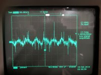
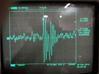
My old scope developed issues and a friend was nice enough to gift me an upgrade so here is the monitor out when looking at a 1Khz signal. The second pic is zoomed in on the spikes riding on the residual, which reads 360-400Hz. Perhaps the compensation on an opamp has gone wrong?
My old scope developed issues and a friend was nice enough to gift me an upgrade so here is the monitor out when looking at a 1Khz signal. The second pic is zoomed in on the spikes riding on the residual, which reads 360-400Hz. Perhaps the compensation on an opamp has gone wrong?
Attachments
Running the Amber 5500 over night, and then doing the SPCL 24 calibration, I get
0.0021% THD+N @ 1kHz @ 3V with GND floating, and 0.0026 with normal GND.
This is full bandwidth but reducing the BW to 30kHz I get
0.0007% THD+N.
What happens if you reduce BW? Can you do that with your version?
0.0021% THD+N @ 1kHz @ 3V with GND floating, and 0.0026 with normal GND.
This is full bandwidth but reducing the BW to 30kHz I get
0.0007% THD+N.
What happens if you reduce BW? Can you do that with your version?
I get 0.0026% @3V on my Amber 5500. It was a few years since it was calibrated.
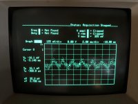
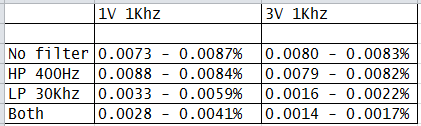
Alright a half hour warm up and SPCL 24 calibration reveals the following numbers. They always fluctuate a bit so here are the typical ranges. Thanks for mentioning the filters. I never played with them much and they do quiet down the fluctuations. Is that typical or should they be steady?
Attachments
I got rid of my 5500 some years ago so the only useful input I have is to make sure there is not some external noise source interfering with it.
Mine exhibited performance similar to what staccatiss reports.
There is a self calibration routine that you can run - no longer remember details.
Mine exhibited performance similar to what staccatiss reports.
There is a self calibration routine that you can run - no longer remember details.
Could it be that your Amber 5500 does not have the HW upgrade and the SW upgrade that comes with it.
The model nr says what options you have.
Are you using balanced connections?
The model nr says what options you have.
Are you using balanced connections?
Alright a half hour warm up and SPCL 24 calibration reveals the following numbers. They always fluctuate a bit so here are the typical ranges. Thanks for mentioning the filters. I never played with them much and they do quiet down the fluctuations. Is that typical or should they be steady?
Model 5500-14000 which means it has the high voltage output option and telecom filters. All the readings were taken single ended.
I'm going to take a closer look at the power supplies. No visual signs of anything wrong but the +/-12 supplies have a small amount of 500hz noise (20-40mv). +19 is a bit high as much as -19 is low.
I'm going to take a closer look at the power supplies. No visual signs of anything wrong but the +/-12 supplies have a small amount of 500hz noise (20-40mv). +19 is a bit high as much as -19 is low.
A quick update. I started exercising some of the options and getting a feel for the instrument and found out something. Input B is more quiet than A and the readings are steady. Looking at the schematic the only difference is relays that switch out the connectors. So its noisy relay contacts  Mouser sells then for $3 each.
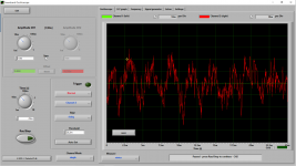
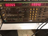
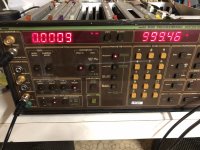
First pic is unbalanced and no filters. Second is with the A weighting filter enabled.
Mouser sells then for $3 each.First pic is unbalanced and no filters. Second is with the A weighting filter enabled.
Attachments
Side note, if you press Shift + A or Shift + B you put the instrument input in an internal loop with the generator. You won’t need a cable to connect the input with the output, the loop is in balanced mode, the best of all worlds for estimating the 5500 intrinsic performance.
I dusted mine, re-adjusted and got 0.0009% @1KHz @3V in 30KHz BW, 0.0012% in 80KHz BW and 0.0006% in A weighted. But I replaced long time ago (where possible) a bunch of NE5532’s inside with LM49710’s.
I dusted mine, re-adjusted and got 0.0009% @1KHz @3V in 30KHz BW, 0.0012% in 80KHz BW and 0.0006% in A weighted. But I replaced long time ago (where possible) a bunch of NE5532’s inside with LM49710’s.
syn08, thanks for the tip. I was looking at doing some of the calibration procedures but the preamp cal can't be completed. It says to adjust two pots through the holes in the top of the card, except the card doesn't have any holes. The components in question are located on the opposite side of the card near the edge connector. But from the look of things maybe the cal is still good.
I recently purchased an oscillator pcb from Victor to really see what the noise floor is.
It's a nice surprise to see all the chips in sockets. Sadly the LM49710 is no longer available and the recommended replacement the OPA1611 is only available in surface mount. Might try using some adapter boards in the distant future.
Programming isn't my thing but I don't mind mucking around in Labview. Next step is building some programs to plot frequency response and THD vs frequency. Should be an interesting task.
That’s also typical for the Amber 5500, and the root cause can be identified in the schematics. It’s not related to the intrinsic generator or analyzer, but to the attenuators frequency responses and noise. The first half could be slightly fixed, but it’s not really worth messing with an otherwise very good instrument, even by today’s standards.
Last edited:
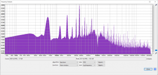
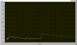
Getting some decent data out now via gpib. Here is a plot of 20-20Khz THD+N using the internal loopback with A weighting. Kind of odd with the jump near 11Khz.
To me this looks like the autoranger switching to another range. You also see this with all AP equipment.
Jan
- Home
- Design & Build
- Equipment & Tools
- Amber 5500 Distortion Analyzer