Under Investigation All my bookmarks from before forum update are gone

I tried to search for my bookmarks and found only one I recently bookmarked, all the others are gone it seems, or what happened to them?

Edit:
It seems I must have mixed up the difference between Bookmarks and the "Watched" on the menu bar where the latter is sort of misleading as I thought "Watched" was a new feature on this forum keeping some kind of log of all threads I have ever watched, checking out "Watched" I just see a very long list of unsorted threads page after page and had no idea what I was looking at as it didn't resemble my neatly arranged and named folders.

It seems like bookmarks are a tool for saving a single post although it works for following a thread too, while the "Watch" is another type of bookmark sort of but only for a whole thread, if I got this right.

The poor thing is, those Watch-marks are now unsorted in random order without any tag/label/folder, and having over couple of hundreds of unsorted threads it's really difficult to find threads let alone remember why a thread was saved as I had lots of different folders for various topics I earlier saved under such as "Resistors", "Capacitors" etc., now it's near unmanageable and useless, terrible.

Will we have a folder option or some other way adding labels/tags for our "Watched" threads in the future, and, are the old folders stored somewhere and can/will they be restored at some point later?

fault-finding on board with an MCU

Can anyone confirm or reject the impression I am getting? I have two circuit boards (in inverter welders) with malfunctions, and each unfortunately has an MCU. All diagnostic procedures (tracing and checking signal paths) lead me to pins of 64 or 44 (respectively) pin MCUs.
I am thwarted by my inability to know what signals I ought to see at these most of these pins (apart from power supply and earth pins) because their functions are programmed into the MCU by the equipment manufacturer.
My hope was that it is possible to download out of the MCU its programme and work out what should be happening, but my Google searches suggest to me that this is in practice impossible.
How do we use the diagnostic skills and techniques we have managed with for years on all sorts of circuit boards if there is this impenetrable device on the board?
To illustrate the difficulty, one of the welders (TIG process) only activates its HF (which is supposed to initiate the welding arc) for a very brief pulse, whereas is should persist until the arc is established. This pulse emanates from the MCU, which should be responding to something either sensing the drop in voltage as the arc establishes, or the presence of an arc current. Both are sensed and their signal paths lead in plausibly fault-free ways to the MCU, but without knowing just what the MCU is supposed to expect before halting the HF, I do not see what to investigate. For all I know, it might be sensing some entirely different fault condition, and halting the HF as a protection measure. But how does one proceed logically?
Any thoughts?

I am Old school looking for SQ car audio

I am in search of a three way SQ car audio system. I have not had anything but an OEM system since 1985. I have considered a DSP and 4 channel class AB channel front end with a class D sub amp. My budget is $1k or less for amplification and DSP.

I presently have Dayton AMT Pod4 tweeters, Dayton RS 100-4" fullrange, Dayton RS 180P-7" midwoofer, and Dayton RSS265HO-4 subwoofer.

My Idea is to run the 4" full-range from 300Hz and up off of front channels. Then rolling it off at about 5kHz at 6db, and setting high pass close to that point with single cap.

I want to drive this system with a DSP that is capable of HD at 32 bit 192kHz. But finding such a unit that will fit my budget is not easy.
I am wondering if there are SQ units available that I can afford.

The only DSP unit that fullfills my cost and capability requirements that I have found is the Cadence DSP4.8. There were some negative comments made about noise and quality issues on the internet. So, that makes me skeptical.
As far as amplification is concerned. I am considering the Sundown Audio SAX 100.4 V2 class AB. And one of the new Sundown SFB-1500D or SFB-2000D class D sub amps when they come available.
Any insight and suggestions will be helpful and appreciated.

If I had the funds, I would go all top of the line Zapco. But!!!!

Power supply bypass caps - how and what

Here is an article I put together about how to deploy proper power supply bypassing capacitors to op amps and split supply circuits.

Types / values / dielectrics / and voltage coefficients are all discussed. What do you guys think? Agree? Disagree? Looking for any feedback or insights that were maybe not mentioned or touched on. Here is the article -

https://sparkoslabs.com/power-supply-decoupling-capacitors/

Attachments

  • OpAmpBypassCapsFI.jpg
    OpAmpBypassCapsFI.jpg
    74.9 KB · Views: 146

Class-D Amp LC-Filter: Coil heating

Hi All!
I am currently designing a Class D Amp based on TIs TAS5504 and TAS5152. I use the TAS5152 in 2x BTL configuration with 2x 10uH and 1x 0.47uF for each BTL. PVdd is 36V

So far it's working, but most of the coils I tested for the output filter heat up for 20-30°C above Tamb in idle (!) mode.
And those Coils are listed as "Coils for Class-D Amps". So I guess the resonant frequency of the core shouldnt be a question.
But to check it: (1) what should be the resonance frequency of the core when switching is done at 384kHz?

Interesting is that the coils do not heat up that strong when I place them in the TI eval-Board. So (2) my layout could be a reason? (I have a very compact board)
Or could there be some jitter on the PWM caused by a decoupling failure? (3).
I measure betweeen 0.5-1.0V Vss ripple at 384kHz. This seems to be a normal value to me (which was also confirmed by a Spice simulation).

Any help, hints or notes would be highly appreciated!

Thx and best regards,
Klaus!


P.S.: I foud the "heating in inductor thread", but this ended in nowhere 🙁

Please explain a servo circuit

I have been reading the forums, and the word "servo" keeps

poping up, I must have fell asleep when that topic was covered,

or I learned it by another name. I have been reading the "op amp

book", I have attached a small quote from chapter 1. Op amps

are very important, and I want to eliminate any confusion I may

have, please explain the servo circuit.

Thank You......

Attachments

Oh yeah another SSE build

After much reading and internal debate I am going to try the following SSE build


Power - Antek AS-2T350 (350-0-350)

Ouput - Edcor GXSE15-8-5K
Rectifier - solid state only


Tubes - JJ EL34L
Choke - Triad C-14X
Motor Run Cap - Pingcon CBB65A 100uf 450VAC


All other parts per standard BOM published on the Tubelab website. I do have a range of cathode resistors from 470 - 680 ohm at hand if need be.


I am very much new to this so will have many questions as I go along. First question of course does any of my choices present issues that will require solutions outside the standard build documentation? I decided to not follow the most standard build by using a toroidal power transformer and opting for ss rectification just because it appealed to me. End goal is to have an amp that will push my 4" full rangers from 80hz and up.

When measuring horns off axis response, which point do you guys measure from ?

I haven't measured a full set of polars from horns for quite a while. I think the last time I did measure I rotated the horn at its mouth (point B in the image) for the measurements.
Over the years I have read some people rotating at the throat end of the horn.

Which is correct ? (where do you rotate if you have a speaker with direct radiator bass units and a horn loaded mid/tweeter ?)

Thanks,
Rob.

Attachments

  • rotation.jpg
    rotation.jpg
    6.6 KB · Views: 97

Linear PSU with supercapacitor(s) - does it make sense ?

Dear Members,

I'm wondering if the huge capacitance of supercapacitors could be any good for DIY audio amplifiers in linear PSU-s. I know a voltage stabilizer (e.g. LM317T) already has a good PSRR (power supply ripple rejection) but how about using 1-2 supercapacitor(s) after the usual bridge rectification ? With current limiting of course to protect diodes (depending of type of course), that little bit of extra charging time is no problem, the main amp circuit is switched after PSU measured OK by the microcontroller anyway.

What do you think ? Has anyone done such a design ? I could also imagine 1-2 supercap(s) and then normal usual "chain" of caps like normal (low-ESR) electrolytes and finally the film ones on top of them. This way "speed" would be assured too, at least this is what I think.

Any advice, pro, cons, thoughts ?
I'm not a pro in electronics so I thank you for your patience 😉

New diy open baffle project: 3-way with AMT

Hi all,

after reading about open baffle designs and projects across the internet for several weeks I am coming closer to an idea what I would like to build myself.
Sine I have only built a few diy kits myself decades ago I hope I get some help in designing my speakers. I do not have any experience with that so far.

Inspirations came from: the pure audio project, spatial audio, GR research, blue plane acoustic, supravox and others.
My first idea was to go for 2* 15" woofer + wideband driver (e.g. Tangband...) but I have changed directions.

My idea is to go for a 3-way system using an AMT as tweeter. Soomething similar to the Spatial Europe mc series no 8: https://spatialeurope.de/portfolio-item/mc-series-no-8-en/

I dont want to play around with DSP or equalizers, I hope to get good results with just passive XO.
My first choice of drivers would be Supravox 215 (or maybe 165) for the mids, a Mundorf AMT (AMT23D6.1-R) with homemade waveguide. A reference design on the Supravox homepage suggest th 285 as woofer but I wonder if there is a good combination utilizing a 15" such as the Spatial Europe speaker.
I also looked into Acoustic Elegance drivers but hesitate because of the very high shipping costs to Switzerland where I live.

On further "requirement" is moderate baflle size, again the Spatial Europe mc no 8 would be just right, as well as the reference design on the Supravox homepage. The intention is that it should not dominate the living room, so about 45x120 cm is on the upper end of acceptable sizes.

For the beginning I hope to get some advice on finding matching speaker drivers, I have set myself a budget of max. 1500 EUR/CHF for drivers per speaker.

Open for inputs! I know that some software exists to simulate different speaker positions and baffle geometries, I plan to do some experiments with these software packages to better understand the implications different options....

Adding attenuation inside active crossover circuit

Hi. I'm designing rev2 of a circuit that will be used between a minidsp 2x4 HD and an Icepower 200AS2. In the first revision i had a volume pot bewteen the last opamp and the amplifier, but this introduced an increasing amount of noise with attenuation. This time i want to feed the amplifier directly (or via a 100r) from the last opamp to prevent this noise. I still need to attenuate the signal, mainly to lower the noise generated by the minidsp. However, i want as few opamps in the signal path as possible, so i wondered if there are any reasons why i shouldn't add an L-pad between the buffer stage and the crossover-section, as drawn below. I've checked that both slope and phase is unaffected as long as i keep the values of the l-pad below 1k. I will be using NE5532.
1646909094439.png

Dali 7 restoration.

I got a pair of these old speakers in the weekend at a fair price, and nearby my home. Thinking of fixing them without paying too much.
Cabinets are in good condition, but the veneer has a 'tan', and a few stains (coffee or drinks, not sure). Suggestions on cosmetic fixes?

Ok, so first thing I noticed was a blown tweeter on one. Luckily these D19 tweeters are common, and I had an extra pair in the garage. However not exactly the same. The originals had stacked magnets, so I only used the face plate/dome from my spare tweeters. I also added a felt pad to the pole piece, and some ferro fluid to the gap. The originals had no ferro fluid, but the spares did have it. I figured some FF would prevent them from blowing again.
The working original had a top octave bump with a sharp null in the response at maybe 15k, this disappeared after the 'fix', but the top octave bump is a bit higher. I'm guessing some reflection from the pole piece gave the null, and it's gone now with the felt. No graphs from the tweeter mod.

The woofers have bad surrounds, so I did a quick glue fix to be able to measure them and listen to the speakers. I have ordered new surrounds, since the listening impression was positive. A little bright sounding for my taste maybe.

So, next thing was to measure the drivers and 'reverse engineer' the XO.
I measured the coils with the XO disconnected, but did not desolder the coils. I think this should be ok for accuracy, but with a question mark for the woofer coil. I did the measurement at 100Hz though, so the parallel RC should not influence much. All caps are el-lyte except for the tweeter. The woofer coil is ferrite core, the rest are air cored.

Measuring the drivers got me really annoyed with the dome mids.. horrible! First thought was to replace them with some cone drivers or some Dynaudio D52's but then again, the whole thing about these speakers are these dome mids... So, I took them apart to see if something could be done. The pole plate is a flat piece of metal, and the center vent is also a piece of metal with some holes, so first thing I did was to put some felt pads on the pole plate, and some Monacor MDM (wool mix) in the vent hole. Sadly this did nearly nothing. Only some minor wrinkles were improved in the high frequencies that are really 'out of band' anyway. So, I figured, I have nothing to loose, do or die 🙂 I added some sticky surround glue to the suspension/VC-joint (front), and some ModPodge in a 1cm wide ring on the back of the dome, starting from voice-coil joint, and 1cm in on the dome. This improved things, but I wanted more. There was still some ringing in the upper band. I made a 'triangle' of sticky surround glue on the back on the dome, with the three tips of the triangle touching the inner limit of the ModPodge. This damped a lot of the ringing in the upper band. Waterfall started to look decent, and FR was improved too.
There is still an annoying bump just over 1k, but it seems the baffle is part of it too, it looks better off center. I have before and after FR of this.

I have taken measurements to be able to simulate it in X-sim, and generally they seem to line up pretty well in phase, but the woofer to mid is a bit troublesome, with a bump in the FR in the XO-area. It seems the design sacrifices FR for phase alignment, and I guess I would do the same. I have played around with it a little bit, but have not found a magic solution. Ok, time aligning the woofer would be nice.. But it seems the mid and woofer don't match too well, and it's not the woofers fault IMHO..

So, if you're bored, stuck at home in quarantine, here is a chance to pass some time 😉 I have seen there has been a few of these group exercises lately, so I thought I would post this one with a slightly different starting point. No driver selection, no baffle size mods etc. I would like to time align the drivers, but it would hurt the looks pretty bad..

Suggestions are welcome. I don't want to spend a fortune on components, but I do have some boxes with XO parts, and LCR-meter to unwind some coils etc.

In general, I think the speakers have potential to sound pretty good. Distortion from the drivers seems low, waterfalls are fairly clean, and the cabinets are pretty nice and rigid.
An odd thing is they used foam right behind the woofers, I might experiment with that, but the bass sounds pretty good 'as is'. The woofers are marked 16ohm, and the rest 8ohm, so they should be an easy load for weak amps.

My thoughts on XO:
-Good phase alignment
-Don't like high Q circuits
-Fairly smooth FR, I prefer slightly sloping down from maybe 1kHz and up.
-No need for crazy power, and they don't have to be 'high efficiency' sacrificing FR either.


About measurements:
-SPL not calibrated.
-Driver offset measurements were taken in two positions: one between tweeter and mid, and one between mid and woofer, at abt 1meter distance. I was trying to emulate a far field listening position in this way. All measurements are in the zipfile. The offsets in the dxo-file are my guesstimates based on this.

Attachments

  • Dali 7.zip
    Dali 7.zip
    236.9 KB · Views: 177
  • mid dome mod.jpg
    mid dome mod.jpg
    144.3 KB · Views: 658
  • std xo.dxo
    std xo.dxo
    113.9 KB · Views: 116
  • boxes.jpg
    boxes.jpg
    576.3 KB · Views: 1,233

Darn it!

Getting harder for SOP. Had an LT1083 fail. OK, NLA. 1084? Ok, if you buy 53 at a time. Had to order a built supply from China. with 2 months wait. It is an even lower noise though. Dual and I only really need a single, but I can use the second supply for the mute relay circuit and it won't glitch the power. Guess it works out.

About possible Babelfish J interest

Well , after some time , I'm able and willing again to bring some Babelfish J packages ; Sort of altered schematic , including cascodes (easily avoidable by choice) for input LTP , biased through my green (LED string ) trademark thingie .

Package would be comprised of :

-pcbs (one layer , usual thickness/color/overlay mumbo jumbo)) , 2 pcs,
-2 pairs of matched J271 JFets - in this project perfect
substitute/replacement for Toshiba 2SJ74BL ,
-2 pairs of BC556C bjt LTP cascode critters,
-3+3 more BC critters for various position
-2pcs of MMBF5486 smd JFets , working as CCS for cascode biasing,pre-soldered on pcbs,
-2 pcs of 1uF Philips MKC (polycarbonate, my fave ) , bypass for critical position - cap for Aleph CCS modulation .

so , end of list; few more details :

Output mosfets prescribed - IRFP150 (one effectively as two IRFP240), just one pair , no matching needed .
Soldering of outputs - either through hole or on wire bridges on upper pcb surface .

Due to cascoding , PSU voltage can be freely augmented for several volts. Also possible multiplying of outputs with some necessary ingenuity , but if there is enough noise , I can make daughter boards for paralleling of , say , 3 mosfets , when there is no need for additional ingenuity :rofl:

That would be all , if there is enough interest , I'll proceed in Swap Forum .

Price - not cheap , but also not overly expensive , considering that rest what you need is available even in nearest Tobacco store .

Screenshot of pcb attached .

and , yes , I know that BJ isn't exactly in VFet/SIT/SIC frenzy fashion category :clown:

edit: forgot schm

edit edit : in a meantime , trade thread opened: Babelfish J package - diyAudio

editeditedit : link to final schematic and parts placement ........ in case that link is Dodo , post is #138

Attachments

  • BJ-sshot.jpg
    BJ-sshot.jpg
    86.3 KB · Views: 6,751
  • Babelfish J.pdf
    Babelfish J.pdf
    51 KB · Views: 2,283

PSU not powering up under load

I have encountered a problem here after having things apart briefly.
The PSU (Connex SMPS 600) will turn on (led light shining, and output voltage is good) when I don't have the amplifier connected.
But if I connect the amplifier board it will just switch what I believe is a relay every second or so.
I tried another PSU on the amplifier board and it started without problems, so I would say it's safe to say that something has gone wrong with the PSU while being out for a while.

The only thing that I can see with my eyes are one of the outputs tabs is moving a little (it's been that way since I got it), could it be bad soldering on the output that stops it from starting up? Not enough current passing through or an instability sensed by the PSU?
My soldering abilities are not the best, so I want to rule out things before I go and make it worse. 😄
Any help is greatly appreciated.

AI Audible Illusions Modulus IIc 2c hum fix

Partial success story. Symptom: Hum, hiss, buzzing, & pops. This started in one channel from the phono section and eventually took over both channels, even from the line stage.

I was motivated. I inspected for open flame, or something obvious. Later, I tapped on each device with a chopstick. Everything seemed to be microphonic. Later (again) I aimed an infrared thermometer at the transformer: fine. I checked each of the larger rectification diodes, one at a time: fine, fine, fine, uh-oh. One of them was 40F hotter than the other three.

When I bought this pre I spent several enjoyable hours reading up on the Modulus history and repair tips. The large diodes are prone to heat, partly because Art mounted them right on the board. The consensus was to use the whole lead so the diodes stand above the board, giving room to cool. Years ago, on AudioKarma, John Curl (!) suggested fast recovery diodes. Who am I to argue?

I installed a pair of NOS, cryo tubes for the phono section. I added a 7 day timer, and an hour clock to the rack.

Plus duct tape between the chassis & the covers. And tube dampers.

Mr. Ferris did not leave much clearance underneath to allow cool air in. I intended to attach Vibrapods with #6 machine screws but... just before I picked up the drill I realized there was not enough clearance to the board! Close call! From a smartphone repair, I had leftover plastic adhesive, so I used that to secure the Vibrapods.

The result is the popping is gone but the hum lives on. (Yes, I eliminated the power amp. When I engage Mute, all sound stops; it's not the power amp.)

Problem with Parasound A21, will not power up

Hello, everyone, I just scanned this forum, and was unable to find any threads that discuss the problem I am having with this Parasound A21 amp. So, I hope someone can help. John Curl? The problem is in the protection circuitry. It is far from straight forward like so many protection circuits I have worked on. At the moment I am trying to understand the function of D18. The amp powers up, but does not switch out of protection. Both amps function with a clean signal, and no DC offset. All the power supplies are looking good and stable. This leads me to believe there is some issue with the protection circuit. Come to find out, D18 is not developing a voltage across C73. Taking a closer look at that circuit, the AC feeding that diode is not grounded! The D19 bridge is working perfectly, so the AC is there. Yet D18 is not developing any voltage across the cap C73. I think this is due to a lacking ground on the AC feeding D18. Any thoughts?

Sharing speakers with multiple Amplifiers

Hi Everyone,

So I have a 2 way switch (https://www.amazon.com/gp/product/B093GSS8P7/ref=ppx_yo_dt_b_asin_title_o01_s00?ie=UTF8&psc=1) and currently I can switch between 2 amplifiers to my speakers. But I built a tube amp and now want to be able to switch at least 3 amps haha

I have not found anything commercially that can do this 😛

Has anyone come across something that can switch between 3 or more amps or have a link to building something ?

Thanks!
Herbert

help Phonic Powerpod7

hello guys,

I am currently servicing a Phonic Powerpod 7 unfortunately the technician from the other shop who serviced this mixer/amp the last time erase the part # on the power modules/ic's.🙁 I emailed phonic corp. and they told me that they do not provide schematics for their products (gee, talk about technical support:whazzat: 
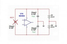
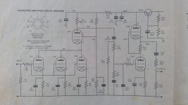
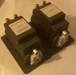
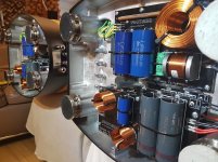
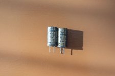
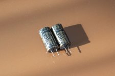
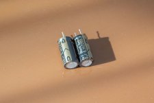
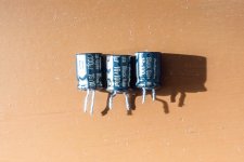
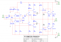
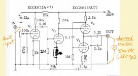
) seems that they are only interested in selling their products. I tried googling and digging for info but none avail. I tried powdering the power ic with graphite to see if I could lift out some markings (ala CSI) but none is left. The power modules where the STK, STR,STV type I guess. Please help me identify the power modules. Thanks a lot.

Best Regards,
Audiomachines

Yamaha M-45 Progress repair

Hi Dear members,

I am currently repairing a stubborn Yamaha M-45 amplifier.
The left channel was blown, so few components down the chain needed to be replaced: output transistors, emitter resistors & few small signal TO-92.
Once this was completed I also replaced all electrolytics with Nichicon UFW series, leaving the original Black Gate capacitors in place.
I have installed multi-turn trimmers for accurate BIAS.
The amplifier turns-on & goes out of protection without hesitation.
BIAS adjustment is working fine in Class A & AB.

The concern I have is the following: (please refer to attached PDF schematic), DC offset at speakers terminal is about 860 mv both channels very close.
Transistor Q109 & Q Q110 (2SC2705) are quickly getting very hot upon powering-up, to give you an idea I measured 75 degrees Celsius after 2 minutes, then I shut off so that I would not risk destroying them. These were replaced with Digikey KSC2383Y to see if there was a difference but unfortunately the problem is the same.
The voltages on the transistors are close to the service manual but not in all transistors.
All transistors have been checked for basic functionality (not leakage).

The differential pair Q101 & Q103 have been closely matched (HFE) and replaced.

The mystery has not been solved & honestly, every time I ask for help all of you have been fantastic and I ended-up resolving the problem.

Attachments

Fremen Edition My_Ref Amplifier – Completed Projects and Photos

A few of us who have been involved in the Fremen Edition for a while realized the other day that been nearly a decade since the project was started and even longer for the My_Ref design that the Fremen Edition is based on. It would be easy for someone on the outside to think no one is building this amp so many years later or that it is an old design that has likely been surpassed by newer designs. Or maybe someone would be put off by the more than 450 pages in the “Build Thread”.

However, this design is most definitely alive and has continued to be improved over the years. It started out as a great sounding amp and is even better today. The basics of the circuit have remained, but improvements in layout by Dario and continuous refinement in the BOM and optional alternate builds have made it an exceptional amp. So, on the suggestion of Stream, we are going to ask builders that have completed a build to post a few photos, talk a little about how it sounds, and compare it to other amps where available.

By the way, Dario has a Group Buy for Fremen pcbs going on right now, the 14th Group Buy for the Fremen Edition. This one is a little bit special because he is trying to incorporate a TO-247 resistor in addition to the current TO-220. This resistor is important to the circuit and the TO-247 size will open up several interesting options for power resistors.

If you are interested, we are trying to recruit at least 4 more stereo kits into the GB to keep the price down and quality up with a European board fabricator.

https://www.diyaudio.com/forums/group-buys/351643-my_ref-fremen-edition-gb-14th-gb.html

So what is a My_Ref amplifier? It is a current pump design using ICs. It is conceptually based on ideas from the Music Fidelity A370 but designed using an opamp as a voltage stage and the LM3886 chip amp as a transconductance or current stage. Mauro Penasa explains his design ideas in the pdf below.

If you are curious about measurements, schematics, etc., see the Group Buy at the link above.

I'll start off the pictures and such with the Fremen Edition in my main system. There is a lot more inside the box than the basic Fremen amp, in fact, its a little bit of a rats nest, but it gets the job done. The blue boards at the bottom of the picture are the Fremen boards and those plus a couple of transformers is all that you need. In my case, I am converting the input from balanced to single ended, plus summing the left and right signal for a sub woofer output. That is the stuff between the blue boards. The boards with the LEDs are a regulated power supply for the balanced line converters.

These Fremen boards have some premium parts and person component choices, for example, Cree Schottky diodes in the power supply and an optional opamp choice with its own compensation. But that kind of thing is for each builder to decide. Building it with the basic BOM still results in a great amp.

As a comparison, I built an amp with an Impasse voltage stage and a Pass F4 current stage. In my system, the Fremen amp is clearly better for both clarity and sound stage. And that's with some pretty expensive tubes in the Impasse.

So jump in if you are interested. The Fremen Edition is a great amp and still improving.

Attachments

  • project_my_ref.pdf
    project_my_ref.pdf
    58.9 KB · Views: 392
  • Freman rear.JPG
    Freman rear.JPG
    302.1 KB · Views: 1,362
  • Fremen interior.JPG
    Fremen interior.JPG
    391.8 KB · Views: 1,418
  • Fremen board.JPG
    Fremen board.JPG
    364 KB · Views: 1,309

SYN 9: a change in direction

For the last two years, ever since meeting T Danley and hearing I could probably cross straight to a 12" using a CD that can reach down to around 5-600Hz, I have worked on that concept.

Built about 6 various-pattern prototype horns that were meant for experimentation, until deemed promising enough to build a pair for stereo.
2 versions became pairs.

H & V degree patterns, ports in corners or middles of horn, mouth terminations (no secondary flares, large 1/4 rounds on primary flares, straight & curved secondary flares), were the variables.
Also played with different cone sizes (8, 10, or 12 inches).
Coax CD's were always the same, 4594HE and dcx464.

All my focus was on improving polars, as both sound and measurements were simply excellent.....and it was the only substantive thing i thought to do trying to find sonic improvements.

All the final versions had close to the same 4ft width despite different H-V patterns.
All sound pretty dang close to each other...too dang close, sigh...all i was achieving were slight lateral changes in sound.

The announcement of the Hyperion, and discussions regarding it and it's close relatives, the SM-60F, SH50, & SH60, caught my attention.

One of the comments often heard about the SH-50 is how it can be relatively hard to locate in space with your eyes closed.
Only occasionally would i hear that phenomenon, and I've always wondered if my builds were missing/doing something wrong.
I chalked being able to easily locate mine up to using a CD all the way down to 500Hz, and saying to myself "How can you not aurally locate a CD handling over half the audio spectrum?".

One thing I found about port location when crossing to a single low/mid cone, is that it makes a 'rob Peter to pay Paul' situation.
Move the port close to the throat to raise the freq response of the cone, and you loose the very bottom end of the cone's response. And of course vice versa if you place the port out in the horn to let the cone dig deeper.

This fact let me realize I couldn't cross to CD higher with a single cone, without further killing bottom end. And I had already been struggling with low end response on every version, all with port centers in the 5-6" from throat ballpark.

So I'm like heck, why not try adding some small mid cones like DSL does.
Plus, my only sonic complaint with my syns has been a sometimes harshness in the HF section in either of the coax CDs. (I've wondered if, despite specs, are they really great when reaching lower.) So adding small mids seemed worth a try,

Well, I call her Syn 9 proto...a 90x60, 31"x19", test sled, with no secondary flares.
Port holes were made, tried, and plugged/patched.... re-holed, re-made, etc.
Using leftover cone drivers.
The small mids aren't even sealed...i just put a couple of wings on the horn to block forward radiation. The 10"s at least have their own sealed chambers.
No matching of CD exit to throat.... 😱
Piece of junk, albeit Millennium Falcon style! (With spot on tuning 😉)

DCX464 HF & VHF
four 4fe35 Mids
two 10fe200 lows

Xovers at 100, 250, 650, 3800Hz. All steep lin-phase.


Well, the sound is such an improvement I can barely believe it.
NEVER heard such clarity before from a speaker.
Tonality rocks with real grit and balls down low (along w dual 18n862 subs).
And that disappearing speaker phenomenon is ....well, appearing 🙂
This beater is my best build yet.....what's the old moto..."use your eyes, plagiarize" lol...but sincerely, thank you Mr Danley

So much for two years of work on a shortcut version....and forever chasing polars....Lol
Now planning a 60x60, 29 1/2 x29 1/2 primary, with two kappalite 3012LFs and four 4NDF34s.
It it's not an improvement, I can always make another beater 😛

syn9 proto horn.jpg
syn9 proto back.jpg

For Sale FS Fountek NeoPro5I

Hello all,
Due to change of plans a set of Ribbon tweeters for sale.

For sale : Fountek NeoPro5I
Once connected for measurements.
Spec:
https://www.speakerland.nl/files/neo-pro-5-i.pdfAsking price €400,- for the pair.
Shipping only EU.

Regards,
Remco

Attachments

  • D7B06959-EFA4-4FCC-9FBD-4D08547E6643.jpeg
    D7B06959-EFA4-4FCC-9FBD-4D08547E6643.jpeg
    536.3 KB · Views: 88
  • A7CC43F6-C19A-479F-8FC5-9E39B7740C35.jpeg
    A7CC43F6-C19A-479F-8FC5-9E39B7740C35.jpeg
    538 KB · Views: 93
  • 86B4D2BC-0D20-448A-8171-0078CFFDA141.jpeg
    86B4D2BC-0D20-448A-8171-0078CFFDA141.jpeg
    574.3 KB · Views: 102

FS: Univ. PSU PCB, Speaker Protection board + parts, Softstart board + parts

[SOLD]
Hi!
I let go of some goodies:

DIYaudiostore's Speaker Protection, board and parts (everything BUT: relays, LEDs, mechanic parts) CHF 18.- (€17)
DIYaudiostore's Soft Start, board and parts (everything BUT: relays, LEDs, mechanic parts) CHF 20.– (€ 19)

The parts have been selected according to the official BOM, and purchased at mouser. I successfully built my jigs with exactly those parts (ordered for 2 sets)

These prices are pretty much exactly what I paid for it (per part, so some came a bit cheaper because I ordered a bunch), plus shipping.


As oversea shipping doesn't really make sense, and I am in switzerland (inside but outside EU), it's more an offer for our fellow europeans.
Shipping is CHF 9.- per package (can contain all 3)

PM if interested.
Thank you!

PCB-less amplifier design notes

Hello guys

some idea of cylindrical or whatever VERTICAL shaped amplifiers... Can be used later in horizontal manner.

Best thing is the airflow that never stops and non solderability or less solder.

Second best is the chance to use various plated wires, nickel plated(nice at low temperatures), gold plated, silver plated rings and so on. brass, iron, steel, they all add and remove something, manipulating with the impedance curve.

Third best is the rings(layers) can be shaped, cuz corners of different shape matter a lot.

Last is that its FUN, from the 70s ( TUBE ERA) and its matrix also.

SMD can be used.

I dont see any cons from this kind of a PCB... nothing is required to build countless layers. No machines are required. Minimal waste is created.

Has anyone tried that approach ? Induction and capacitance can be made out of wires...lich wires, anything can be used to make capacitor between layers(miller caps and so on).

I have never tried this, but i am planning to.

So guys, Is there any cons ?

Attachments

  • oldisgold.png
    oldisgold.png
    54 KB · Views: 285
  • oldisgold2.png
    oldisgold2.png
    296.5 KB · Views: 283

Linn Akurate 221 Sub

I recently acquired this sub inexpensively and on powering up, it was DOA. It sounds like the power relay inside is just continuously cycling.

So, I removed the screws on the panel in back, and Voila! Nothing!
The amplification unit doesn't come out. It rocks a little, but won't come out. I've looked at it 9 ways to Sunday and still can't extract the amplifier.(Yes, this is a little embarrassing) I've removed the feet, peeled back a portion of the label covering the faceplate which has revealed no hidden screws, & rocked it side to side till I'm blue in the face. It won't come out. Anyone ever played around with one of these??

This may sound like asking for free tech support, but I am an avid audiophile who has great interest in audio as a hobby with the goal of refurbishing some older stereo equipment.
I'm an old guy now, so I have the time 🙂

Main system upgrade

I've been thinking of upgrading my main living room system for a while, but was undecided whether I should. It mostly looks like this:

IMG_20181028_213047_357.jpg


IMG_20210919_163549.jpg


It's a "2.1" system with active crossovers. The top speakers are powered by the two amps sitting on the floor, while the sub has the amp inside. What I would like to improve is:
  • replace the top speakers - while they sound quite nice, I think I can do better
  • build the second sub - I have the driver and amp, I need to build the enclosure and the power supply
  • replace the amps with something smaller, probably chip amps, and have everything (including the crossover) plate-style on the back of the speakers. I want to get rid of the cable mess as much as possible.
  • build some acoustic panels for the room they're in

The subs are SB acoustics and I'm quite impressed by how well they sound, so I've been looking at using their drivers for the tops. For the woofer I'll use the the SB17NRX2C35 6 inch. As for the tweeters, I'll list some potential candidates below and maybe get some opinions on them:
  • SB29RDNC
  • DC28F or RST28F from Dayton
  • Vifa XT25BG60
  • Scanspeak D2604/833000

The crossover frequencies will most likely be 75Hz and 2.5kHz. For powering them I have two options:
  • LM3886 for both drivers
  • TDA7294 for the woofer + LM3886 for the tweeter

I already have boards built for the second option, but they don't have the crossover included. I'd like to design a board that has the crossovers and the amps and make it as small as possible. Then I could choose whichever combination. I was also looking at TPA3116 boards.
As I said, I'd like to have all the electronics mounted on the back of the speaker. I initially thought of placing them inside the enclosure, but with a sealed design I don't think power dissipation will be adequate. And then there's the issue of sealing the plate so that air doesn't escape. So I'll have some sort of small enclosure on the back of the speaker, with the heatsink on the outside. That is probably the biggest challenge.
Anyway, I'll post the progress as I go.

Hypex UCD400 stereo kit with problems

Hi guys,

to get some experience I have recently assembled an UCD 400 stereo kit from hypex exactly according the assembly instructions inside the original housing, which works pretty fine (sounds even more accurate compared to my ML431); some days ago there is some not very loud hum with a hiss in both speakers in a statistical manner with much less amplitude than the oscillation frequency which you can see on the output with the scope. This is only few seconds and disappears afterwards. First I thought that it may come from the preamp (ML380) which is connected symmetrical via XLR on both sides, I disconnected the XLRs at the amp but nothing changed. The speaker cables are pretty short (less than 1 meter 4mm2)

Does anybody have some ideas/hints/experience with this weird behaviour?
best regards
Dieter

Paid members can now choose to turn ads on or off

We are fortunate to have many diyAudio members who have chosen to support the site financially through a yearly membership subscription.

Prior to the migration we allowed those members to turn ads on or turn ads off. Some have let us know that they'd be happy to keep ads on, in order to further support the site.

Due to some limitations in the new software we couldn't provide that functionality until now.

All paid members now have ads turned on by default, but will see a notice at the top of their screen directing them to their user options so they can turn them off if they prefer.

We trust that by giving our paid members the power to choose this is a beneficial move for our members as well as the health of the forum and its ability to remain independent.

Cheers 🙂

  • Article Article
Better SNR in active circuitry

In designing DACs I've figured out from listening that I need to strive for the lowest possible noise in my circuits, even well below the noise on a 16bit recording. This was rather a big surprise at first, but how low to go in noise before lowering it further makes no difference?

In order to get a handle on this question its interesting to consider how good an SNR can be got from simple IC (opamp) circuitry - the lowest noise opamp I've been using is LT1028 which has input noise around 0.9nV/rtHz. This corresponds to noise at the output around 130nVRMS. Hence relative to a nominal DAC output level of 2VRMS an SNR of 144dB. In practice though there are normally resistors in the circuit and they'll contribute noise beyond that of the opamp, given the LT1028's noise is roughly equivalent to a 50ohm resistor. A 50ohm working impedance in the circuit isn't really practical as it'll call for significant drive current, beyond the capabilities of an unassisted opamp.

Rather than chase noise lower there's another approach - push signal levels higher. But then we run up against the 2V output standard - if our DAC outputs a maximum level higher than this it won't be widely compatible with existing audio kit. But if there were a low enough noise means of attenuating the output of a higher voltage DAC then there could be a route to running much higher signal levels within the DAC. It seems to me there is only one solution - an autotransformer as a simple resistive attenuator will either be power-hungry to drive if low noise or too noisy if practical to drive. Since an autoformer is in effect a tapped inductor the impedance seen by the active circuitry is that of an inductor whereas the noise level will be that of the copper winding resistance.

Having wound transformers in the past using ferrite cores (because they're cheap and easily available) I decided to look into what impedance (and hence noise) might be achievable. I have a box full of RM12 cores left over from an earlier DAC project, PC40 material which is good to about 0.35T, resulting in 185 turns per volt to handle 20Hz. I found I could fit about 2100 turns of some 0.16 outside diameter wire on. So about 11.3V peak at 20Hz. The resistance end-to-end was ~100ohm and the inductance just a smidgeon below 22H, corresponding to j2700ohm at 20Hz. So not a big challenge to drive, just over 4mA peak current.

As a 12dB attenuator the resistive portion of the output impedance was in the region of 25ohm thus an SNR of 147dB should be achievable if the preceding electronics was completely noise-free. A promising start I reckon. With signal levels 12dB higher even a lowly OPA2209 can achieve an SNR around 148dB (excluding resistor noise).

Having an autoformer on the output of the DAC makes me think I should use that as the primary volume control in the system. So that's the next design challenge.

Where is the "do NOT like" button for a post???

EDIT: I am also proposing in lieu of "do not like" a rating scale for posts or (better) threads like we had in the old software

I think the new "Like" button for posts is great. People can show their agreement of the ideas within a post with a single click instead of having to write a an entire follow up post that will appear later in the thread.

At the same time, I think it is only fair that there should be a "do not like" (thumbs down) button. For example, when someone is posting about some audio phoolery or giving bad advice this would be a way to show general approval or disapproval that might give the reader some hints about how to consider the content of the post. I understand that this might breed some negativity, but sometimes too much of a protected safe space is a bad thing.

Forum members, do you agree that posts should have a dislike button?

Is there another approach that might be use to voice concern about a post without posting a reply and getting into a flame war?

B&W 802 D2 crossover upgrade

I would like to introduce project that started ~1year ago, and was finished this weekend. Overall this project was very successful and I learned a lot of new.
In the first phase we measured original state to assess what aspects could be addressed and improved in new crossover.
Fortunately original crossover are easily accessible from the bottom as they are in the plinth.
Full measurements and story is here:
B&W 802 measurement

Attachments

  • 20210313_164707.jpg
    20210313_164707.jpg
    251.3 KB · Views: 2,408
  • 20210313_164914.jpg
    20210313_164914.jpg
    242.3 KB · Views: 1,839
  • 802D2 v5.3 Kocour.png
    802D2 v5.3 Kocour.png
    224.6 KB · Views: 1,040
  • 802D2 orig crossover graphs.png
    802D2 orig crossover graphs.png
    218.2 KB · Views: 1,087
  • Like
Reactions: Zvu

-9V supply for Philips 212

I feel like this is something I should have a better understanding of, but I'm not quite finding what I need.
This is the regulated supply for the Philips 212 belt drive turntable.
I had to replace T441 in this circuit. It was a germanium and I only had silicon parts to try. I got it set to the right voltage by increasing R472 but I only get 0.35mV on the output until I probe between ground and TS441 collector with my fluke. So I guess something is just on the threshold of where it wants to work. Is there something else I need to adjust?

I'd just throw in a regulator IC but it seems neither mouser or digikey have any -9V regulators like an LM7909. Or I could just built and insert a new discrete circuit. The original circuit differs from the standard designs I'm finding. R583 would be a zener, D457 would be a resistor, and D458 wouldn't be there.

Attachments

  • philipsPS.PNG
    philipsPS.PNG
    33.8 KB · Views: 165

  • Locked
"audiophile grade" fuse holder??

So, I'm going through my power amplifier and "upgrading" (among other things) the 14 guage power cable. Of course, one lead goes to a post on the fuse holder, a rear hex nut; panel mount type; for 1/4" x 1-1/4" fuses - and realize that in comparison to the fairly hefty solder "post" connection coming out the rear of the holder, the other solder connection, part of which "loops around the barrel" of the holder, is "really puny" and can "flex easily" - certainly in comparison to the conductor I'm trying to solder to it.

Any of you notice this - what I would call "weak link" in the "power supply cabling chain"? AND have you evaluated, and could RECOMMEND a part number and manufacturer of what I hope would be a "more robust" holder?
THANK YOU

Charles

Yeah; and we can talk "audiophile fuses" later.......?!

  • Locked
Resolved - Bug Squashed Page selector on mobile missing at top of page

Regards:

I just tried the new forum on a smartphone. It works well. My only problem is with the page numbers. If I want to go to a specific page, or just simply go to the prev/next, I have to fully scroll down. Even if I don't want to read the actual page from top to bottom. It would be useful to have the page selector on the top AND on the bottom, just like it is on the desktop mode.
Also the first and last page does not have the Go to page selector (obviously it does make sense at 4 or more pages).

This is being looked into.

Resolved - Implemented "Threads", "User Posts", "Commercial" naming and default display order

I mentioned this at the tail end of another thread but I think the issue for that thread had already been resolved and the thread not revisited by admins.

Coming to the site you get the list of posts. Often the one at top of the list is something like 20 to 40 minutes old. Click on "New Posts" at upper left and you get new posts. Click on the "diyAudio" link logo at top left and you go back to the earlier list with most recent post being the 20 to 40 minute old post. Is this way of working intended?

Also while here , would like to ask for option to have more per page as on the old site.

Thanks

  • Locked
Resolved - Not being investigated further Translator issue

I have noticed what might be a disproportionate number of non-English posts, and some exceptional circumstances. Long term members are on occasion posting in their native language, which I wouldn't expect as much as I've seen.

I am also seeing quoted posts where the quote differs from the original post by being in the quoting member's language. I'm thinking this indicates the quoting member is reading through a translator and it is not working properly.

  • Locked
Resolved - Not being investigated further Slowness

Hi, I experience very slow response (2-3 seconds) when I click on the Forums button on the top left. The list of forums comes along after a long delay.
This is on a low end PC (AMD E1-1200 CPU, 8GB RAM, Win10, Opera browser).
I tried it on a more powerful PC. It is faster (within 1 sec), but the slowness is still noticeable.

Resolved - Not being investigated further Forum index bookmark no longer working properly

Prior to the new look, I used to be able to go directly to the Forums index page via a bookmark. Now it takes me to a login page, where I get the message "oops, we can't find this page". Then I must click on Forums page to open the the Forums
1). When this occurs I am in the automatic login mode. (Or remember me, etc,)
2). The address I am taken to: < https://www.diyaudio.com/community/login.php?do=login >
3). I am auto logged in when I arrive there.
4). I access the internet always on my desktop, never by phone.
Is it possible to make a bookmark that will take me to the Forums Index page directly? Thanks

Sota Cosmos: to restore, or?

Hello fellow DIYs
Recently I made a rather bad acquisition. I always wanted a Sota Cosmos, and this looked like a decent table. Turned out not so much. It’s an early unit, and would cost too much (for me) to upgrade it to current status by Sota. So my choices are: 1. Selling it as is; 2. Parting it out. 3. Trying to fix it, and to do this I need technical help, because not much info is available. It has three major problems:
1. Speed inconsistency, which can be fixed in two ways: rebuilding motor-associated electronics and hoping it will work, or buying new Eclipse motor/controller from Sota, $750;
2. Lip on platter does not seem to hold the vacuum too well. “Seem”, because when I do recommended by Sota test - sucking on the vacuum line - record does get sucked to platter and I don’t feel any leaks. This has to be done by Sota, another $500;
3. Vacuum pump is acting strange, and I actually don’t know if it’s because the lip is not sealing, our electronics are at fault, or the pump is not pulling enough vacuum. I know that pump is supposed to pull maximum at the start, and then slow down. Well mine doesn’t do it. It stays on all the time. The records seem to stick to platter pretty well, afterI help them by tapping my finger on the edge to overcome that stiff lip. If I knock on record’s surface I can tell it’s snug against the platter. I news help with electronics, since no schematic is available for the vacuum control. I could just stupidly replace everything, but the pump itself I couldn’t find. The fittings at the pump are rather ugly and not sealing right.
I have to say that when it’s speed instability is at its minimum, this things sounds really great. But if I can’t solve the problems, I will have to get rid of it one way or another. I have a ton of pictures of some guru is willing to help me. Thanks in advance.

Dubious Scan Speak Discovery build quality?

Last week I managed to buy a Scan Discovery 8" midwoofer just before prices went up, today I unpacked ir and got somewhat underwhelmed.

First thing to mention is the eco friendly packaging - its nice and biodegradable but paper dust was all over the cones. As it is slightly sticky on the magnet size there is no way to make it perfectly clean.

Then it got worse. Its a woven fiberglass cone. On one driver there is a torn filament - I'm sure it makes totally no difference to the sound but once I noticed it hurts my eyes even from a distance 🙂 There is some excess glue betwen surround and the chassis. Chassis holes are not perfectly centered, there are some rough edges...

I had similar observations when I bought a Scan Speak Discovery 10" passive radiator for my Peerless XLS sub. Even though XLS was made in China, build quality wise I had nothing to complain about, while Scan PR had mounting holes slightly off center. Nothing to really complain about but on Peerless these were perfectly aligned.

Its not like I had tons of drivers in my hands but the few Tang Bands and SB Accoustic units that I have really leave nothing to complain, everything looks smooth, symmetrical and clean. On the other hand every review of Scan Speak drivers stresses great build quality and I had the feeling that Scan Speak is a premium brand.

Given what I had in my hands I'm disappointed but maybe its not really representative? How is Your experience with Discovery line finish and build quality?

Attachments

  • IMG_20220309_214746.jpg
    IMG_20220309_214746.jpg
    618.6 KB · Views: 182
  • IMG_20220309_215310.jpg
    IMG_20220309_215310.jpg
    674.6 KB · Views: 180
  • IMG_20220309_214909.jpg
    IMG_20220309_214909.jpg
    223.5 KB · Views: 184
  • IMG_20220309_215111.jpg
    IMG_20220309_215111.jpg
    234.1 KB · Views: 173

Resolved - Implemented Change the option for number of posts per page

The only thing I'm waiting (patiently) for is the max number of posts per page to be raised to 50 again. Its probably just a psychological thing but a 1000 post thread with 50 pages of 20 posts seems more of a slog than 20 pages of 50 posts
Yes, also it helps to have more posts on a page...
1. when replying to multiple posts,
2. when comparing between posts,
3. when searching through posts, and
4. when coming back to a thread the next day so you don't have to go looking for the second last or third last page so often.
  • Like
Reactions: PRR and JRKO

Powering a LED from the input signal in a passive loudspeaker?

Hello,
I was wondering if it would be possible to power a LED from the input signal in a passive loudspeaker?

Of course the LED could be lit only after some signal would have been sent to the speaker.
Obviously some AC to DC converter should be used.
Maybe the energy from the signal could be stored in some big capacitor to smooth out the energy variations in time?

Then, how to get the correct and stable voltage?

Painting woofer rubber surrounds

I had my 12 inch paper cone woofer surrounds replaced some years ago. However the repairer used a horrible off grey rubber instead of the original black coloured surrounds. I have never been happy with them and after many years I want to paint the rubber surrounds black. Firstly, can this be effectively done without altering the woofers characteristics and secondly what type of paint can I use without effecting the rubber surrounds? Cheers ....

Used ( and NOS) Black Gate Caps

The capacitors were purchased from Parts Connexion and are 100% genuine


Black Gate F capacitors 6.3v 2200uf (lot of 2 caps)150euros
Black Gate PK capacitors 25v 47uf (lot of 7 caps) 70euro
Black Gate STD capacitors 100v 10uf (lot of 5 caps)50 euros
Black Gate STD capacitors 16v 470uf (lot of 2 caps)40 euros
Black Gate STD capacitors 220uf 16v (lot of 2 caps)30 euros
Black Gate STD Capacitors 100uf 16v (lot of 3 caps)30 euros
Black Gate STD capacitors 50v 10uf (lot of 18 caps)150 euros

Black Gate PK 4v 220uf (lot of 2 caps NEW)20 euros

Shipping internationaly , but i cant be held responsible for any import taxes outside of European Union
If you have any questions please let me know

Attachments

  • _DSC6669-2.jpg
    _DSC6669-2.jpg
    175.3 KB · Views: 93
  • _DSC6670.jpg
    _DSC6670.jpg
    399.9 KB · Views: 84
  • _DSC6671.jpg
    _DSC6671.jpg
    348.7 KB · Views: 82
  • _DSC6672.jpg
    _DSC6672.jpg
    215.7 KB · Views: 101
  • _DSC6673.jpg
    _DSC6673.jpg
    287 KB · Views: 86
  • _DSC6674.jpg
    _DSC6674.jpg
    282.7 KB · Views: 92
  • _DSC6676.jpg
    _DSC6676.jpg
    469.1 KB · Views: 88
  • _DSC6677.jpg
    _DSC6677.jpg
    432.7 KB · Views: 84
  • _DSC6678.jpg
    _DSC6678.jpg
    446.9 KB · Views: 79
  • _DSC6679.jpg
    _DSC6679.jpg
    459.2 KB · Views: 77
  • _DSC6680.jpg
    _DSC6680.jpg
    519.4 KB · Views: 78
  • _DSC6681.jpg
    _DSC6681.jpg
    421.2 KB · Views: 82
  • _DSC6682.jpg
    _DSC6682.jpg
    493.8 KB · Views: 80
  • _DSC6683.jpg
    _DSC6683.jpg
    416.8 KB · Views: 82
  • _DSC6684.jpg
    _DSC6684.jpg
    326.8 KB · Views: 85
  • _DSC6686.jpg
    _DSC6686.jpg
    372.9 KB · Views: 86
  • _DSC6687.jpg
    _DSC6687.jpg
    315.3 KB · Views: 77
  • _DSC6690.jpg
    _DSC6690.jpg
    587.1 KB · Views: 83
  • _DSC6691.jpg
    _DSC6691.jpg
    621.7 KB · Views: 97
  • _DSC6692.jpg
    _DSC6692.jpg
    699.6 KB · Views: 103

Burson audio V6 classic review

I have built my first DIY DAC then bought V6 classic but I burnt it for my mistake.
Carlos from SSaudio offered me a free replacement for reviewing.Thanks a lot!
I have to say that I have not much experience for engineering or audio DIY and no measurement so it's just my opinion.
Also listening room is small and listened with low volume.

I have OP07,LME49710,AD797,MJM5534D
My favourite was AD797 so I have compared with Ad797 and V6 classic.

Equipment
Speaker: SB acoustic satori 2way (Xover designed by joachim Gerhard)
Source :Tidal and SSD data ripped by CD - Roon ROCK(Nuc8i3beh fanless chaiss,linear PSU)
Amplifier:Babelfish M25 r.2
DAC:Nos ad1862 DAC designed by miro1360 through JLsound I2SoverUSB

Music
Norah Jones "I've got to see you again"
First impression is V6 classic have wider sound stage but thinner or transparent.AD797 have less wider sound stage but more punch in bottom.
Difference in vocalharmony,AD797:2 people is singing at different place. V6 classic:harmony could hear transparent.
When I listened strings,I noticed V6 have much better expression.

Hariprasad Chaurasia "Masters of the reed"
Bansuri sounds much more detail and beautiful with V6. Also tanpura sounds better.
This is amazing, I have never enjoyed listening bansuri with audio equipment before.

Diga Rythem Band "Magnificent sevens"
Vivraphone sounds more 3D with V6.
Baya sounds more 3D like with V6.
When sound is clowded,AD797 sounds like more detailed.
Bongos sounds better with AD797,Also feels more rhythmic with AD797.

DouDou N'diaye Rose-Djabote "Diame"
This track was recorded at night outside. From sound of insects,I feel like I am standing there with V6.
Mixed chorus,Ad797 sounds more detailed but not sure which sounds beautiful.
Percussion sound is similer results with previous track.Ad797 has more punch in sound.

conclusion
I like V6 classic pretty much especially for simpler acoustic music.
It is expensive but now for me,It was worth to buy.

Attachments

  • PXL_20220304_030933791.MP.jpg
    PXL_20220304_030933791.MP.jpg
    446.9 KB · Views: 105
  • PXL_20220304_030830468.MP.jpg
    PXL_20220304_030830468.MP.jpg
    470.8 KB · Views: 109
  • PXL_20220304_030552888.jpg
    PXL_20220304_030552888.jpg
    522.6 KB · Views: 110

Cat Proofing Speakers

Hi Guys,

My new cat has caused some damaged to my newly DIY built stand mount speakers. He jumped on top by clawing his way up the front baffle tearing the rubber surround of my Satori MW16P-4 bass driver which will now have to be replaced by a new one.

I was wondering if anyone had any cat proofing ideas.

There is no front grill, I think a cloth grill would not have helped.
I don't know of any metal grills which fit the MW16P-4 very well.

Thanks.

SSE Weak/Fuzzy Right Channel

I built up an SSE a few years ago, listen to it daily and really love it. About a week ago it started getting a really weak quiet right channel. Swapped the power tubes and put in different tubes, no change. Opened it up and look for loose connections, or anything showing obvious damage, but could not find anything. Does anyone have any recommendations for starting to trouble shoot with the multi-meter? Any suggestions appreciated, thank you!

DS18 PRO-FR3500.1

Owner says he has seen a lot of this amp model with a similar problem. What happens is under high load (1~2 ohms) pulled to clipping (Clip LED on), the amp completely freaks out and draws about ~200-~300A (13-14vDC at amp terminals) current from my bench. Output on the scope goes absolutely wild. At first, I thought this amp was actually OK because it reacts relatively normal for a Class-D, that is until it hits clipping. Then all heck breaks loose. Im honestly surprised the amp is surviving pulling this kind of current.

Rail is +-70vDC
Output clips at about 65vAC

Seems to me, this amp may actually be clipping too early on.

Has anyone seen this before? Its a Type-3 classD with 14 pin drivers. Rail voltage too low? Rail caps are 100v.

Rubber restorer Denon cassette deck

The take-up reel in my Denon cassette deck (1989 vintage) is slipping, so my tapes are being eaten. No doubt the rubber idler wheel that drives it is old, hard and shrunk. Is there any stuff I can use to restore it (for a while anyway)? I searched but didn't find anything current. I can always buy another deck for next to nothing, but this is afterall DIY and I can't resist fixing things unless all is lost.
Thanks for any help!

Open Baffle 3-way Neo3 and Neo8 in Modified Joseph Crowe Horn Design

IMG_0941.jpg


I wanted to try the open baffle thing and have purchased a few speakers to play with, Goldwood 8024 8" (high QTS), GRS Neo3 clones (only ~$30!), and some older Madisound Neo8 clones. I'm also pretty handy with CAD and 3D printing, so I purchased the CAD files for the Neo3 horn that Joseph Crowe offers.

https://josephcrowe.com/products/es-1600-biradial-horn-for-bg-neo3-3d-cad-files
I modified his design to also hold a Neo8; even though the body of the Neo8 is wider, it has the exact same width 4-hole wide arrangement across. I think it would be amazing to 3D print the horn with a Bronze-filled filament and polish them up a bit.

https://colorfabb.com/5-years-bronzefill
I'm a little bit concerned with running a first-order cross-over between the Neo3 and Neo8, and would appreciate yalls thoughts.

https://hometheaterreview.com/first-order-crossovers-panacea-or-problem/
As mentioned in the above article,

"The other problem with first-order crossovers is dispersion. Because the filters are relatively shallow, both drivers are simultaneously audible when sounds are within about an octave of the crossover frequency. This is no problem if your ears are at the same distance from the drivers. However, if your ears are closer to one driver–if you stand up, which puts your ears closer to the tweeter, or slouch down, putting your ears closer to the woofer–the sounds from the two drivers will no longer be in phase at all frequencies. They’ll be in phase at some frequencies and out of phase at others, which means some frequencies will be boosted and others attenuated, and you will no longer be getting even frequency response. (Speakers with higher-order crossovers can also have this problem, but to a much lesser degree.)"

How likely is dispersion to be an issue? What's the best way to measure dispersion effects?

Attachments

  • Capture2.JPG
    Capture2.JPG
    266.6 KB · Views: 322
  • Capture.JPG
    Capture.JPG
    227.1 KB · Views: 354
  • Like
Reactions: Joseph Crowe

My 34c9 (omnidirectional full range with 3FE22) build

I built a pair of unique speakers designed by DiyAudio member claudiogan (the design is discussed here: 34c9 a MDD full range speakers.)

I was attracted by the unusual look and simplicity of build, not talking about low price. I made some slight changes to the construction so I could use various bits and pieces I had at hand.

I ordered the 3FE22 speaker, since it was in stock in CZ. As a bonus, it is also smaller and lighter - so I did not need a hole in the base. The Al pipes are 20x20 with 1.5 mm wall thickness, they were ordered online already precut to correct lengths. I made the pipe holder from a piece of pine plank. Also, instead using plumbers putty, I cut four little triangles out of 5mm plywood and glued them into the corners to create surface to mate the speaker to. For looks, it was sprayed black and covered in vinyl self adhesive wallpaper (to hide my wood working skills🙂 ).

There are two M5 threaded inserts for mounting to the L bracket. The screws are also holding the pipes by screwing in and pushing the pipes against the opposite wall. The mounting is shown in the pictures.

The bases are again a piece of 18mm pine plank with a small riser, so that the bottom of the magnet has some free movement.

I decided to arrange the pipes into a spiral after a test of both arrangements (in the pictures) since there was no difference in sound and measured FR. The pipes are glued together with contact cement.

Now when the pair is finished, I will experiment with a little of foam in the open ends, the initial test shows a slight improvement.

The sound is truly omnidirectional and there is a wide listening area. There is lack of bass as with any 3" speaker, which will be solved by an active subwoofer.

And this was the first pair of speakers that my wife actually wanted to put into the living room (and I had to say no🙂 ) I highly recommend anyone to build this speaker. It is really fun to listen to.

Update: 3D printed base pictures in post #36

Attachments

  • IMG_0337.jpg
    IMG_0337.jpg
    771.5 KB · Views: 1,750
  • IMG_0338.jpg
    IMG_0338.jpg
    642.4 KB · Views: 1,701
  • IMG_0346.jpg
    IMG_0346.jpg
    913.8 KB · Views: 1,690
  • IMG_0392.jpg
    IMG_0392.jpg
    300 KB · Views: 1,680
  • IMG_0386.jpg
    IMG_0386.jpg
    879.8 KB · Views: 1,681
  • IMG_0387.jpg
    IMG_0387.jpg
    984.9 KB · Views: 785
  • IMG_0393.jpg
    IMG_0393.jpg
    700 KB · Views: 640
  • IMG_0510.jpg
    IMG_0510.jpg
    992.8 KB · Views: 610
  • IMG_0512.jpg
    IMG_0512.jpg
    655.2 KB · Views: 631
  • IMG_0450.jpg
    IMG_0450.jpg
    996.4 KB · Views: 734

RPI4 + DigiAMP + CHN50 build & questions

I have an RPI4 (2GB) + DigiAMP running with some CHN50s. I'm building the speaker boxes using 9ply.

The entire lot is powered using a SMPS - a mean well 90W 19V medical class 1 power supply. The SMPS is reasonably clean but I noted that the RPI is raising the noise floor when attached causing a set of peaks across the spectrum (approx 4Hz apart). So I decided to make a LC low pass filter (not entirely designed but simply with the bits that I have around).

The power from the SMPS -> L -> C C C C C -> DigiAMP+ onboard regulator -> RPI4.

The LC is a big Coilcraft 470u 3+Amp shielded inductor (these have been used in 400V power before). I then have two WIMA MKP 1uf and a WIMA 0.22 FKP plus two 25V 1000uF no-name low ESR caps salvaged from a dead SMPS.

Pk-Pk AC noise is now at ~43mV at the speaker. However I have a stronger 14.17kHz peak that rises to about 60dbV. On investigating this doesn't appear at the power supply, which is quiet as a mouse on the input side of the LPF. It also shows on the power point of the DigiAMP+ next to the power jack.

So I'm thinking that the RPI or DigiAMP+ has something onboard that's causing some noise at 14.17kHz. Has anyone experienced this?

Now I could test this without the RPI4 connected, to see if it's the originator but I have a feeling this may be a little more involved. It seems too low at 14kHz to be CPU power saving, so I'm thinking this may be one of the aux/HDMI output?

How does this floating shield work?

On this well regarded schematic the shield is connected by a resistor to the output. How is this better than tying the shield to the ground? Regarding its working mechanism the only guess i can make is that the output current saturates the shield and pushes out the emf. Also the shield now modulates with the signal so maybe thats a good thing too if we're after eliminating non signal related influences?

Also if my guess is correct then couldnt a similar method be duplicated with an amplifier pcb by using ground pour for the output trace which would flood a whole layer of pcb?

Attachments

  • fig_02.gif
    fig_02.gif
    34.8 KB · Views: 214
Projects by fanatics, for fanatics
Get answers and advice for everyone wanting to learn the art of audio.
Join the Community
507,737
Members
7,886,213
Messages

Filter

Forum Statistics

Threads
406,143
Messages
7,886,213
Members
507,737
Latest member
vinylwall