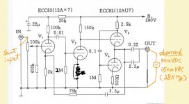
The value of 2M for grid current biasing (while 10M seems to be a more common value), at line level and as the second stage, seems strange to me. What is the (intended) benefit of this?
A classic three-stage amplifier with negative feedback and no obvious high frequency control. Three amplification stages are enough to generate a phase shift more than 180 degrees, so you have an oscillator.
I would normally have designed the second stage to have a higher current than the first. The second stage uses self-bias and a low current. I would use normal cathode bias and grid resistor and a lower anode resistor which will reduce the gain somewhat.
One of the stages needs to have the frequency response controlled to stop it oscillating. I'd try a grid stopper as Jan suggested, first, perhaps in the region of 1 to 10k in series with the grid of the second valve. That is where the voltage in the chain is highest. If you use a cathode resistor as also suggested the gain will be reduced but if necessary can be regained with a bypass capacitor (unless that causes the gain-phase relationship to become a problem again).
And, I note you don't have a load connected. That allows the gain to reach its maximum. You may want to consider an RC network to maintain the expected load at high frequencies, which will, once again, reduce the overall gain and may bring some stability to the circuit. The "R" would be whatever load you expect and the "C" something to provide loading above audio. (At least, I assume the expected load is lower than the feedback resistor).
Thanks all your suggestions and regarding.
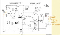
I modified the circuit and attach here . Feedback resistor original value is 22K now change to 16K.
Seems it still have a bit problem so i want to add grid stopper on V1.
Not sure anything i can try ?
I modified the circuit and attach here . Feedback resistor original value is 22K now change to 16K.
Seems it still have a bit problem so i want to add grid stopper on V1.
Not sure anything i can try ?
Attachments
Last edited:
Why ?? That increased the feedback which usually increase susceptibility to instability.Feedback resistor original value is 22K now change to 16K.
I would not expect oscillation - and if it did the amplitude would be much bigger. Check your B+ supply (switching?).
Just to back up a bit ... it would be useful to know exactly what oscillations you are seeing.
Valves have very high input impedance and easily pick up stray signals. In old days of point-to-point wired valves intervalve signal leads were invariably coax screened cable. On a PCB I would have ensured that there is at least an earth screen around grid leads. Have you done that?
Is the input you are seeing due to noise - really an oscilloscope pic of the output would give us a few more clues. If you do not have one can you borrow one or take your circuit somewhere it can be measured?
Is there a need for bootstrapping the output stage? If you disconnect the 0.1uF from the top anode and connect it to ground so that the lower triode is just a current source (more or less) and the top triode a cathode follower, does the oscillation stop?
- Home
- Amplifiers
- Tubes / Valves
- My pcb based diy preamp seems oscillate