FS: Salas Folded Simplicistic Phono Stage + Paradise Preregulator

For sale Salas Simplicistic Phono stage LMC 63db version with Teabag Pcb's, Nichicon Muse capacitors and MKP1837, all parts from Mouser. Silver mica and K73-11 signal capacitors. Load resistors are generated by an LDR resistor replacer.
The phono stage is powered by a Paradise Pre-regulator from GB Diyaudio, a small LDR power supply has been added. The original BLOCK transformers are not rigidly fixed to the PCBs and foam and lead have been added to make them even quieter.
The whole is connected with a professional connector, is perfectly functional and sounds great. I am selling it for lack of time. In the last 2 years I turned it on about 10 hours in total.
In the state in which it is found in the photographs, I sell together for 350 330 euros + shipping and Paypal fees.
Best regards
Guglielmo
Italy

Attachments

  • 20220123_172508.jpg
    20220123_172508.jpg
    489.6 KB · Views: 425
  • 20220123_172527.jpg
    20220123_172527.jpg
    379.8 KB · Views: 366
  • 20220123_172811.jpg
    20220123_172811.jpg
    649.9 KB · Views: 369
  • 20220123_173530.jpg
    20220123_173530.jpg
    413 KB · Views: 370
  • 20220123_173613.jpg
    20220123_173613.jpg
    488.9 KB · Views: 427
  • Salas1.jpg
    Salas1.jpg
    371.6 KB · Views: 433

Power Amp Front End with integr. OpAmp and Signal Pad by Power Supply Rail - Naming?

There are some commercial and diy power amplifier with an operational amplifier as front end.
At some of them the signal pad comes from the regular OP-AMP output.
But there are a second kind of signal out.
In this case the normal output from OP-AMP goes of GND (resistor between 100R and 1K) and the signal comes from the positive and negative PIN for the voltage supply.
What is the colloquial term of this topology and what are the pros and cons? (in post #4 one will find the right information).

I need this information to find appropriate design rules for such a front end on the web.
I asume, that the rules for replace the OP through a better version from currently production (like the LME series from NS resp. TI are not the same compare to cases, where the signal pad goes about the normal output.
Who can call me the term for this topology? Thank you for this information.
Here is a good description of this topology:
https://www.analog.com/media/en/tec...tes/58052492001115525484056221917334AN211.pdf

Speakers with two woofers

Hey guys, I have an old pair of Sony SS U501’s they have a mid range, tweeter and woofer. They look as if they have two woofers, but one is a blank - I put two new woofers in and wired them parallel I did not touch the mid or the tweeter, but I am wondering now should I change the wiring setup for those as well? Seeing I added another woofer, did not know if it would affect the mid and tweeter. These are 8 ohm speakers if that helps.

2.1 Boombox - Seperate full range from sub?

Noticed when looking at designs that some separate the sub from the full range drivers, giving them very little room to breathe. E.g

https://boenicke-audio.ch/products/loudspeakers/w5/

while others throw them all in a single box like the B&O Beolit: https://fccid.io/TTUBEOLIT17/Internal-Photos/Internal-Photos-3210730

Also seen people build the Isetta with and without separating the full range drivers: https://sites.google.com/site/undefinition/portable-and-tabletop-speakers/isetta

Anyone have strong opinions which way is better?

Alternatives for Erse Super Q Laminated Iron Core Inductors for Martin King OB Speakers

I am hoping someone can help a newbie. I am building Martin King’s open baffle speakers and have everything ready to go but have been waiting for Parts Express to ship the ERSE Super Q 4.0mH (0.22Ω) and 9.0mH (0.346Ω) 16 AWG 500W Laminated Iron Core Inductors for momths. However, I gather from reading a post here and from watching Danny of GR Research that Erse may not stay in business. I have looked around for similar inductors and am baffled (No pun intended). Can anyone help with alternative suggestions so I can get these speakers built?
Thanks,
Tom

Need expert advice on a vintage tube amplifier- !!!

Hello, I am in great need of help, as a diy Newbie i just don't know enough. I have a Vintage Tube amplifier - It's a Fischer Integrated Tube Amplifier that is missing the main Input Transformer, How easy is it to find a modern replacement and will it hurt the performance of the amplifier compared to the original main input transformer? It still has the two Output transformers, can it be saved? And what company would you recommend? -- -- Thanks, Dean

TIL (today, I learned)

This thread is dedicated to knowledge "learned today"...

I'll go first.

Today, I learned my Audio Techinica ATH-R70x are not only headphones, but microphones in parallel with the output (line and HP amp are the same output in this case)... If I hit them like a drum, my subwoofer mimics it. This isn't an issue, as I don't leave them plugged in, just interesting... I knew headphones were also microphones, but I've never had any that made LF.

LED tube biasing, pros and cons

I was wondering if there is any reason to try LED biasing of a 6j5 in a SE amp where this tube is the driver for a 6550? I am using a 1w resistor now. If i put the LED in how do i set it up other than just replacing the resistor? I know different LED colors correspond to different voltage requirements. Does that mean i need to select the color according to my voltage drop? Thanks for all the help.

【need help】Has anyone measured the resistance between the LME49810 VCC/VEE and GND pins?

I've found some used LME49810s that I'd like to collect, but I'm having trouble judging if it's genuine. After the production was discontinued, the high price made fakes appear on the market~
Its font seems to be slightly different from 49830, and the stroke lines are a little thicker.
Sadly, for some reason, I'm currently unable to build a circuit to test it.

Previously, I successfully differentiated LME49830 quickly with reference to the experience of others. The pin resistance between VCC/GND of the genuine 49830 is approximately 60kΩ (Pin15 and Pin3), and that between VEE/GND is approximately 40KΩ (Pin10 and Pin3).

Out of the same idea, I want to know what is the resistance value between VCC/VEE and GND of LME49810, can anyone help me measure it? thank you all😉


111 (2).jpg

Install Question

I have 2 digital designs amps hooked up in my truck .

1 of the amps is hooked up to the midrange speakers and the other map is hooked up to the tweeters .

When the amps are hooked up in the truck the amps do not work they don’t power up I checked the voltage at the amps terminals and I get 5 volts .

If I unhook the amps and I test the power and ground wires I get 14.4 volts .

I pulled the amps out of the truck and bench tested them and they work perfectly fine .

I went back and tested the battery and ground wire measuring the voltage on the power wire with the black probe to the ground wire and it reads 14.4 volts . If I hook the amps back up I get 5 volts on the power wire .

Any ideas what might cause this ?

Persistence.

One thing I have learned over the years is with troublesome or new electronics is to be persistent in trying to find faults or solutions to problems.
Giving up at the first problem just isnt on.

In 1980 I was fed up with being a labourer so went to the job centre.
I noticed a training scheme called TOPS (training opportunities scheme.)

So I did the maths entrance exam.
I failed by a few percent.
So went away and swotted up on the things I couldnt do in the exam.
Went back for a resit and passed (just.)

I started the industrial electronics course in July 1980.
On the first day I was looking forward to learning some electronics but got met with another maths exam to make sure we had enough to do the course.
I struggled badly even with some of the basics.
I was given some extra lessons learning maths to catch up.
After my first week studying electronics and maths we did a weekly exam and I barely scraped through.
My tutor said he was worried I wasnt going to make the grade.
One of the other chaps left the course due to problems.

I caught up with the maths and got up to speed with the electronics by also studying in my spare time in the evenings.

After a month or so we did a weekly exam and I was only one to get 100%.
At the end of the year we did city and guilds exam in industrial electronics and I passed with distinctions.

I guess the moral of the story is dont give up.
Just put the effort in and you will eventually get by.

I watch videoe's on youtube about Einstein and other geniuses and some of them got poor exam results early on.
But they kept going and eventually made it to the top.

NAD 320BEE capacitor query

Hi, I've just opened up my NAD 320 BEE and noticed that one of the big 15000uF 50V capacitors in the power section is starting to bulge. I've found what I think is a suitable replacement but the service manual says the original cap has a 10% tolerance. The one I'm hoping to replace it with has a 20% tolerance. Is this likely to be a problem? Many thanks for taking time to read this.

Buzz after changing tubes in preamp

Hello


I have a very interesting problem.

Recently I have ordered three Gold Lion ECC83 tubes for my DIY Marantz M7 preamp. I wanted a change in my system so I decided to change old JJ ECC803S’s. I have swapped the tubes and started it up. After the initial warm up of heaters, high voltage kicked in and immediately there was a buzz on my mid-range speaker on only right channel (there was no buzz with JJ tubes).

Tubes played beautifully, but there was that buzz (does not depend on a volume level).


I measured it with oscilloscope which can be found in attachment.

So I decided to swap tubes one by one with JJ tubes to find a problem (JJ tubes are still good). First one was the cathode follower tube (U3 on schematics, in attachment). I swapped the tube and there was no buzz. So I had two Gold lion tubes (preamp section) and one JJ tube (cathode follower) and the buzz was gone. Then I wanted to check if that tube is bad. I swapped JJ tube from cathode follower (U3) with another Gold lion tube from preamp section (U2). JJ tube was now in preamp and Gold lion as cathode follower again. The buzz was back.


So my conclusion is that the problem is in the Gold lion tube as cathode follower and that the tube itself is not bad. It seems that the Gold lion tubes are more sensitive than JJ tubes.

I tried to shield the tube itself with an improvised shield (aluminum foil wrapped around cardboard tube box and connected to GND) but there was no difference.


The high voltage is regulated with linear regulator and the heaters are powered via DC voltage (linear regulator as well). I have posted schematics, pcb layout, oscilloscopes measurements and photo of the preamp inside the housing.


On the preamp_1.jpg photo, red lines are AC line of power supply and green lines are AC lines for VU meter lamps that can be switched on or off (the tube buzzes either in on or off position). All AC lines are quite far away from the U3 tube.


So my questions are:

- what could be the problem?

- why is only the Gold lion tube affected with this and why the JJ tube is not?

- why did I hear u buzz in my mid-range speaker on only one channel (difference between buzz in left and right channel)?


Thank you in advance

Attachments

  • Gold_Lion_osci.jpg
    Gold_Lion_osci.jpg
    347.1 KB · Views: 115
  • Gold_Lion_osci.jpg
    Gold_Lion_osci.jpg
    347.1 KB · Views: 107
  • JJ_osci.jpg
    JJ_osci.jpg
    353.3 KB · Views: 140
  • preamp.jpg
    preamp.jpg
    617.6 KB · Views: 126
  • preamp_1.jpg
    preamp_1.jpg
    624.7 KB · Views: 131
  • preamp_layout.png
    preamp_layout.png
    102.4 KB · Views: 129
  • preamp_sch.pdf
    preamp_sch.pdf
    62.7 KB · Views: 138
  • scope.jpg
    scope.jpg
    453.7 KB · Views: 135

Orbitsound Dock E30 inspired single box stereo speaker - design considerations

I really like the Orbitsound Dock E30. The sound quality is great, airsound effect cool and it is small enough to fit into a suitcase when traveling by car. I would be afraid to put it into checked luggage while flying. This gets me thinking...

Here is some nice exploded view: https://barnabyward.com/project/dock-e30

Showing us that:
  • all three speakers share the same volume
  • there are three passive radiators

I wonder how all these interact. I wonder if the small full rangers are something one can buy or if they are custom made.

Also, the "airsound" effect is adjustable, it says +-12 dB - would that be just a simple relative volume for the S component? One review said that at minimum setting the sound si practically mono (need to try that).

I wonder if something of similar performance in a smaller travel friendy package (with lower SPL of course) could be built. The box itself could be 3D printed, it could use e.g. three of these https://www.madisoundspeakerstore.com/approx-2-fullrange/sb-acoustics-sb65wbac25-4-2.5-full-range/ or maybe, on the cheap side, Visaton FRS-5X or maybe the 2" inch Sica full range or smaller BMR drivers? I should still have some TEBM35C10-4 from another project. Any suggestions? My favourite 3FE22s would end up with a too large box...

For the bass, this looks like a possible solution (taking 0.5l of volume though and quite expensive for what it is): https://www.soundimports.eu/en/tang-band-pr08-a.html. Any other suggestions for low volume bass? Maybe a bit of EQ boost would be all needed - and it would save one amplification channel as well.

For the amplification, I have tried some nice small bluetooth class D amps, there are plenty of them. No option for EQ there, some have bass/treble EQ built in, but I prefer the ones without. Powered from a laptop brick, since I always have at least one with me.

While thinking out loud like this, I think the BMRs will be a good start in a simple printed box with external processing and amplifications. Then, at phase 2, all of this would be built into one box. Another line on my never ending list of potential projects🙂

Dual power to single power rectifier filter

While browsing I stumbled across this little unit.
https://www.google.com/url?sa=t&rct...0636547.html&usg=AOvVaw1cK44bh8dR93w0nk2DjbJz

As I have several +/- trans that I have removed from none working units over time, I wondered in it would be any good to convert them to a single line.
Also if I had say a +/-25 VAC tans rated at 300 watt. What could I expect when passing the voltage through this unit. More VDC of more power, or no change?

Cheers

Strange output transformer measurements - please help explain

I have a pair of custom made PP output transformers on EI130 laminated core. The core is a common laminated silicon steel core used in mains transformers. The number of primary is 2 x 1600, the number of secondary turns is 2 x 80. The turns ratio is 20.
Now I wanted to measure the primary inductance, so I connected a 1:1 isolation transformer to the primary and applied 240VAC to it. I measured 12.1VAC on the open secondary, which is about good. The primary current was about 0.8mA. From the XL = 2*PI*f*L I calculated XL = 300kohm, and L = 950H. Is it realistic? I think it is a bit too much 😳 I still have to measure stray capacitances, and where they resonate with the stray inductance.
I also tested it by loading the secondary with a 12V car headlight bulb. Considering the primary and secondary resistive losses all is good. The DCR of the primary is 285ohms, the secondary is 0.5ohm. I had 130mA on the primary and 8.7VAC on the secondary. It seems that is 26W power flowing through the transformer, and the bulb gets some 22.5W after the secondary loss.
Anybody ever measured a commercial OPT? What primary inductance and resistance you get normally? Perhaps my open-circuit measuring method is not correct.

6N2P-EV vs 12AX7

Can someone speak to similarities and differences between 6N2P-EV and 12ax7, given that:

Both are wired for their correct pin out @6.3V in the same circuit and the power transformer has adequate current for either.

(I believe 6N2P requires 40ma or so of additional current over a 12ax7)

Some have said 6N2P-EV to be more closely related to a 6SL7.

I’d rather not rehash the better known differences, but instead get down to what might be some differences “beneath the surface”

Opinions abound as to where they stand in the scheme of things. With the best NOS 12ax7’s in “absurd” cost territory, what do you all thing of the 6N2P-EV’s worth in circuits traditionally with 12ax7’s?

What are the relevant differences we might need to consider?

My understanding is that if the 6N2P-EV is an equivalent, it would be at least in theory superior to the 12ax7 as from what I gather it has a grounded shield on pin 9 to reduce crosstalk? They also seem to be rated for more hours and are built to be more robust (for mil application). They are also WAY cheaper than a 12ax7 Telefunken!

By the same token I’ve also heard 6N2P-EV has more fluctuation from sample to sample.

I have swapped 6N2P-EV and 12ax7 and heard repeatable differences, but I’m not sure if the same would probably be true if I swapped 12ax7 for 12ax7 of different make or manufacture. I.e. just normal variance.

I didn’t do double blind testing. I’m just not set up for it, so take my casual observations with a grain of salt.

Unfortunately also i don’t have a curve tracer or I’d do some detective work... but I’m greedily eyeing the uTracer so that might come to fruition sooner rather than later.

So, I figured I’d ask those much more adept than myself:

Can I assume the 6N2P-EV is a drop in, given attention to the above or is there something I’m missing?

Are the data sheets accurate to real world samples? Same operating points?

I wonder if anyone out there has gone through and tested a couple dozen or so of these from different factories and can provide some info as to their spread as well.

What are the best years and factories?

Are there other 6N2P suffixes that are superior? I believe EV is a ruggedness criteria.

As an aside: Someone I spoke to who was from Russia mentioned that from Gorbachev onward the quality of tubes and other mil parts was not the same. He said he definitely wouldn’t buy tubes manufactured in Russia after 1991 but ideally none before the mid-80s. Do others share this view?

Thanks in advance for your thoughts and insights.

Questions regarding wavelets and phase measurements

We spent saturday afternoon and evening to align a 5 way horn system using wavelets. I have two questions about the method and the resulting phase measurement.

1. When using wavelets I would assume that you set delays of both speakers so that the center of the wavelets align, not the first sine peak as shown here (From top to bottom: 1. original signal, 2. low-pass filtered with LR4, 3. highpass filtered with LR4, 4. sum of both filtered signals):

wavelet.png

The green line IMO shows the correct point to align them, the red line clearly shows that this point in time would be ambiguous as the low pass filtered signal has a longer period length, the high pass filtered one has a shorter period length. only point they sum correctly is if the center of the wavelets are aligned. All in all that should be plausible, the summed signal also shows a 180° phase shift at the crossover frequency as is to be expected from a LR4 filter.

Are my assumptions correct?

2.: Here's the minimum phase as generated from a measurement in REW for the whole system at the listening place (grey: phase, axis on the right - purple: SPL, axis on the left):
spl_and_phase.jpg


I thought that each of the 4 LR4 crossovers would show a 360° phase shift around the crossover frequency? Why does the resulting phase appear to be almost flat from 20Hz to 20kHz? Seems that either something is off here ore my assumptions about the 360° phase shift of LR4 summed signals are incorrect. OTOH as I pointed out the top graph clearly shows the 180° phase shift at the crossover frequency for the summed signal. I'm a bit puzzled here. Maybe I misunderstood what the term "minimum phase" really means, would these phase shifts from the LR4 filters not show up in the minimum phase plot?
  • Like
Reactions: krivium

Frame grid voltage triodes for audio?

I want to learn about small frame grid triodes, how do they behave differently from a coiled grid triode in V1, splitter or driver positions? What was their reason to come into use? etc... I'm organizing tubes to clean the basement for Easter and see I have a crapload of 2HK5, 3HK5, 4HK5 and 6HK5 tubes. And probably other frame grid tubes too when I start to look them up. When I started this hobby I was buying TV-repair tube caddie's at swap meets whenever I saw one.

Google didn't bring up much about ?HK5 tubes for audio. Anyone try ?HK5 for audio?

https://frank.pocnet.net/sheets/201/6/6HK5.pdf

2ohms or more ... good quality speakers?

I am not sure if this is the right section, but if a moderator thinks it should be more appropriate to be posted in the multi way section, please do it for me!
I'm looking for a good quality and probably higher SPL than usual pair of 2ohm speakers for a germanium amplifier that cannot withstand high currents and high voltages.It can deliver 1... 3 Amps and up to 6...7v rms and that's just all about it...so i'm looking for a nice speaker or multiway speakers that can move very well on this "magnificent" output.
It may be that a 4...8 ohm regular high spl speaker would do the job, but i'm not experienced in this area so i'd like to hear your advice. I thought that maybe the Fostex fe line would be a good value for the money and pretty sensitive but i'd like to keep this topic open for anything around the idea cause i might not have anything against going active and multiway thus multiplying the power with each additional amplifier although I wouldn't look to power anything more than just a normal living room like 5/4/2.5 m yet if it's a padded room it may need more watts than what I'd expect.
Thank you!

Dream multicell horns

Some days ago, I had a dream about friend's band playing on a small stage with a strange PA system. There were so.
me subwoofers of unknown type, but on top of them were huge multicell horns - 4x4 cells, mouth size maybe 120 x 120 cm, each cell had its own full range cone driver around 3-4" size. Since the cells did not have to come to a single point, the front was less curved than a single driver multicell.

Has anything like that ever been used? Or built? I vaguely remember discussing such an idea here.

I can see this with 3FE22s with ca 30x30 cm mouth cell. Is it a completely stupid idea to build such a monster? I imagine it could have a killer low distortion midbass to midrange and very high sensitivity. I wonder at which frequency beaming would start. If such a thing could be optimized in size to be usable from 150 (200) Hz to 3-4 kHz and used with a matching dispersion horn tweeter, it could be an impressive system both visually and sonically - since I really liked my printed multicell horn.

Zyklop: interesting new FAST by Visaton

Hi all,

Here is an attractive new design by Visaton, a FAST crossing at 270hz towards their B80 full range speaker.
Cleverly, the BR opening is between the FR and bass cabinets. It does look nice, for sure:

An externally hosted image should be here but it was not working when we last tested it.


visaton_zyklop.jpg


Details (in German) including plan are here:

ZYKLOP

Zyklop

Listening test in magazine Hobby Hifi can be found here:
Strassacker: Lautsprecherbausätze (Lautsprecherboxen-Bausätze) und Lautsprecherlösungen
I don't have the magazine to see the measurement under 30 degrees but they say that it is best to orient the speaker towards the listening position, the B80 beams from 5000 hz upwards.

Comments?

Visaton W130X

Friends I am new in DIY and found a driver Visaton W130X that is different and not much data on implementation.

Idea is for 2 applications Powerful Bookshelf 2 way maybe 1 Full and 130x as woofer or 2 woofers

and a Compact Hideaway type subwoofer that can be used for music and movies
1-2 drivers room is 16ft -25ft
Experts please suggest

regards
anand

Simple Universal Speaker Delay Using A Triac

This project is aimed at those wanting to add a simple speaker switch on delay to an amplifier to eliminate the annoying and possibly speaker damaging thumps/pops/bangs that many amplifiers make when first powered up and the sometimes strange noise when powered down.

The term "universal" comes from the idea that the design can be scaled to suit most amplifier power supplies and that the delay time is adjustable.

The aims of the design can be summarised as,

1. To work with a wide range of transformer voltages.

2. The switch on delay must be repeatable and reliable and must give the "full" delay time even in the event of a brief mains interuption or cycling of the on/off switch.

3. The relay should drop out near instantly on power off.

4. Power saving is used by running the relay at reduced coil voltage yet with a high voltage "pulse" to close the relay smartly and reliably.

These points will all be explored by understanding how the circuit operates. That in turn should enable the user to be able to alter the circuit to suit their own requirements.

The circuit...
I drew the circuit in Spice more for clarity as much as anything else, however I found that it was possible to simulate it as well although the component
values used in the simulation are different from the "real world" values that the circuit works well with. This simulation problem is almost certainly
caused by the Triac model used. So on to the real circuit... understand how it works and you can modify it to suit.

(And why a triac ? To "kick" the relay with a high pull in voltage require that the device driving the relay operates quickly. A transistor "drifts" into
conduction as the base current rises which would not pull the relay in quickly enough when the relay is fed from the power saving series resistor feed)


The power supply.
D1, C1 R1 and R2 form the PSU for the circuit. The AC feed can be taken from across one or both secondary windings depending on the voltages of the
transformer. The circuit is not ground referenced in any way.

D1. Half wave rectifier.
R1. Can be added if desired. A small 0.5 watt resistor both acts as a safety feature (consider it a fuse) and also might make life a little easier for C1.
R2. Helps discharge C1 when power is removed.
C1. Is the "reservoir" cap. The small value ensures a rapid drop out of the relay on power off. This cap should be of good quality, possible a slightly larger 100 volt component as these have a more generous ripple current rating.

The timing components.

R3 and C2. These are the "timing components". R3 has to be "low enough" to supply sufficient base current to Q1. So to alter the delay C2 value can be
varied.

The trigger circuit.

D2, R4 and Q1
D2, the zener ensures that no base current flows until the voltage across the timing cap has reached the zener voltage plus vbe of Q1. R4 ties the base of
Q1 to ground to ensure it never "floats" when the zener is non conducting. Q1 conducts when base current flows. Q1 should be a reasonably high gain device.

The Triac.

The triac is a BTA16-600SW device. This is a "sensitive" gate trigger type (easily triggered) and has a low "minimum holding current". Triacs are
interesting devices and can be triggered in one of four "quadrants" depending on the polarity of the voltage across the main terminals. Once triggered the device remains conducting and can only be turned off by interupting the current flowing between the main terminals.

(Refer to the pinouts of the triac in the data sheet AND NOT the LTspice symbol which to me is back to front)

MT1 connects to the relay.
MT2 connects to ground.

The triac is triggered by pulling the gate to ground. This is done by trigger Q1 as explained earlier.

The remaining components.

The relay coil is fed via a series resistor. You will have to determine the value of this depending on the relay. Get this value correct and the relay will
run on a much lower coil voltage than its rating saving power and producing less heating in the relay. My relay was a 12 volt 500 ohm device. There is nothing to stop you running two relay coils in series or parallel depending on what suits best. The triac seemed happy with holding currents below 10 ma.

C3. This "kicks" the relay with the full supply when it activates and ensure a smart and rapid pull in. The value can be up to a 100uf if the supply
voltage is low. Even a 22uf works well on the higher supply voltages.
D3. The clever bit. When the triac triggers the voltage on MT1 falls to near zero. We can use this to pull the voltage on the timing cap to near zero via the diode. This ensures that the timing cap is ready to "start again" should there be a brief mains interuption or quick operation of the on/off
switch. The diode also serves as a snubber network across the triac in series with C2.

Real world components values.

470K and 47uf works well for the timing components R3 and C2. These give around an 8 second delay.
For 18 Vac input the zener should be around 6.2 volts.
For 36 Vac input a 15 volt zener is better.
R4 is 560K
Select the series feed to the relay to suit.

The pictures.

1. The circuit diagram (but refer to text for values)
2. The timeline of operation showing the delay, the voltage across the triac and relay and the relay current.
3. A close up of the transition period.
4. The relay "kick" current.
5. The triac pin outs. A1 and A2 are "main anode" which equate to MT1 and MT2 (main terminals).

Finally the zipped folder contains the simulation files which will run in LTspice.

Attachments

  • Simple Speaker Delay.JPG
    Simple Speaker Delay.JPG
    128.5 KB · Views: 2,496
  • Timeline Of Operation.JPG
    Timeline Of Operation.JPG
    119.7 KB · Views: 2,357
  • Current And Voltages.JPG
    Current And Voltages.JPG
    110.7 KB · Views: 1,946
  • Relay Kick Current.JPG
    Relay Kick Current.JPG
    95.5 KB · Views: 1,862
  • Triac Pin Outs.JPG
    Triac Pin Outs.JPG
    31.2 KB · Views: 2,162
  • Simple Speaker Delay Simulation Files.zip
    Simple Speaker Delay Simulation Files.zip
    4.5 KB · Views: 361

Sony CDP-C201

Hello,

I am new here, so my apologies if this is in the wrong area. I have a Sony Stereo system from 1990 that I am trying to restore, the CD player a Sony CDP-C201 is giving me some trouble. It’s very intermittent where at times the laser housing will not lift to read the CD, when this occurs just lifting with my finger fixes the issue for the time being. I have applied Super Lube to the gears, but did not know if there is another lubrication area that I should be looking at? I’m pretty novice at this and don’t want to damage anything beyond repair.

Should I get a Fluke or a cheaper multimeter?

My old Craftsman multimeter was lost in a car Break-in. I've decided to build an Amp Camp Amp and a Korg Nutube preamp and then whatever this new hobby (rabbit hole) puts in front of me. Should I get a Fluke 289, with graphing capabilities or a cheaper multimeter and a bench multimeter or an oscilloscope? I need a multimeter in my tool box and I play with electronics a bit.
Does anyone have some wisdom that might help me to get tools that will help me without wasting a lot of money?
Thank you in advance for sharing your wisdom and/or point of view.

Cambridge audio a1 mk1 not powering on.

Hello so i bought a cambridge a1 mk1 (the original version) off someone and they said that the main board glass fuse blew and to change it and it would work. However after changing it the amp still doesn't turn on.
None of the other fuses had blown, it was the T3.15A which blew which is the last fuses. I also read a few youtube comments which said it could be the transformer since none of the first fuses blew.
Can anyone help me?
I have a DMM so can test things if needed be.

Rookie questions

Building my first set of speakers and keep coming up with questions. They are the Swans HiVi 3.1. Ordered parts for the upgrade. I soldered all the parts just like the pics because i wasn't sure if the caps and resistors were directional. There is only one coil upgrade and i was wondering if it was directional, or didn't matter which leg went where. The other coils were self explanatory.
Thanks Paul

Sharp SC9570AV distortion, missing output channel

~15 year old, wasn't plugged in/used for past 3-4 years.

I have a recording of the working speaker, kind of cracking high distortion. Nothing out of the other one. These are using his 120w. I have some 10w PA speakers that both work on, so it probably has issues with the higher load from the 120w speakers but I might be wrong

I brought a 40W PA amp to his house and hooked his speakers to and both sound fine on it

Caps DO look good, but might be dried out

First recording is on AUX from Cable receiver. That in itself sounds worse than the second selection, which was the receiver

I know it's not a high quality brand that some of you deal with, but this man dosn't have much money right now, cost him a good bit back in the day. Single package amp, I think A-B, on fairly big heatsink with fan

CD does not work but I bet it's the belt

Attachments

Pignose Hog 30 repair and mods

I have recently come to possess a Pignose Hog 30, which I would like to use with my bass ukulele (Self contained electric acoustic u-bass) (yes I know my ubass has it's own built in amp, but I still have the output available and I'm hoping to get even more volume).

Of course the Hog is old, and the lead acid batteries are long gone. A couple of the pots are broken from over-tightening, but these should be pretty simple to replace. But for the batteries, I am thinking to go with li-ion and improve on the run time and weight. So I am wondering: the TDA7240A amp and the NJM4558 op amp in this thing can actually take 18V, so why not run it on 18V and make it a little louder? Would this damage the rest of the circuitry? Obviously I will have to get a different charger, but I would anyway get one that matches to the battery I get. I am looking at 18Vpower tool batteries as a good option. Obviously these will run a little over 18V when full, but this should not be a problem for the chips, right?

I also found this mod: https://www.talkbass.com/threads/is-there-a-pignose-for-bass.74568/#:~:text=I've had a,resistor (was 47k). and it obviously sounds simple and desirable. So I am interested to know if there is a risk of damage to anything doing this? What about doing both - increasing the voltage and the gain mod?

See the schematic and chip datasheets attached.

Attachments

Pre - Estate Sale : Cool Rare parts and accessories

Hi All,
It's been awhile since I have been active on this site, situations beyond human control have taken me away from my beloved audio hobby, and left me in a fight for life. Unfortunately, that fight has been lost; cancer has won, and now, I am dying. That said, I am now starting to go through the years of accumulation,and begin liquidation of my toys. Cancer treatments / surgery are horrifyingly expensive, especially when one doesn't have great insurance, and I am trying to be able to pay for a decent burial, leave my other half a little something, and honestly, put food on the table for the next little while. This is the first pile of stuff that I've gone through, there will be much more to come! Make me offers folks, no reasonable offers refused! I accept Venmo and Zelle payments. Thanks!

Krell Industries: CD clamps / center pucks for the early MD series cd transports, Model KDI. Quantity 2, asking $100.00 each. These are impossible to find, for the most part.
Krell Industries Star - Clamp cd clamp. For the KPS20i & 30 players. Rarest of all, and the only clamp that these machines function with. $300.00
Gryphon "The Exorcist" : Interesting little system / cable demagnetizing widget. Super-clean condition. $150.00

Theta timebase linque conditioner : Anti - jitter box. Nice condition. $200.00

Acoustat MK-121-2A electrostatic interfaces. With the famous (and preferred) Medallion series transformers. This is the second pair I owned, was going to build myself another pair of 3x4 electrostats, but never got around to it. Asking $350.00 for the pair. SOLD

Selenium D3300ti - 2" throat high-frequency compression drivers. VG condition. Nice-sounding, smooth drivers. Asking $200.00 / pair

Miscellaneous VPI, Rega, etc. tonearm counter-weights, many available. $50.00 to 100.00 each.

Bozak B199a - 12" woofers. 2 pair. 1 is good, original condition, second is still original except that one cone was poorly patched after it was damaged (not by me!) Asking 200.00 / all 4

Velodyne various subwoofer drivers. 2- 12" DD series (servo), one 10" DD series (servo), and 2-MASSIVE 8" (not sure of series). Asking 125.00 each for 12", 100.00 for 10", 200.00Pair for the 8" units. 107.JPG108.JPG110.JPG111.JPG112.JPG113.JPG114.JPG115.JPG116.JPG135.JPG137.JPGDSC00267.JPGDSC00268.JPG

Attachments

  • 098.JPG
    098.JPG
    392.5 KB · Views: 94
  • 099.JPG
    099.JPG
    390.5 KB · Views: 104
  • 100.JPG
    100.JPG
    627.2 KB · Views: 108
  • 101.JPG
    101.JPG
    414.2 KB · Views: 89
  • 102.JPG
    102.JPG
    322.6 KB · Views: 99
  • 103.JPG
    103.JPG
    355.8 KB · Views: 91
  • DSC00269.JPG
    DSC00269.JPG
    411.2 KB · Views: 94

LAPT problem

So im making one P3A more .....
This time i thought like testing 1216 -2922 Lapt combo
if my rails are more or less up to 36+36 volts i am ok above that i get oscilation
anyone gan guess why?
is it because 1216-2922 is lapt ?

with in the day i will replace them with the standard 1302-3281 combo to make sure thta nothing else is wrong in the circuit and get back ...

this is a bit weird since all the rest is pretty much the same and i ve made this board and choice of parts a gozillion times .

Stability issues in LTP with elevated grid

I'm currently fiddling around with a tube preamp prototype, in which I've decided to try out using a 6SL7 differential amplifier/LTP as a front end. The operating point is set using a cascoded BJT-CCS in the tail. This is then AC-coupled to a grounded-cathode amplifier stage, which is DC-coupled to a cathode follower as a final stage. Both of these stages uses a single 6SN7.

To make it easier to stabilize the NFB-loop, I have tried to DC-couple the feedback path from the cathode follower to G2 on the input stage LTP. Therefore, the grids are elevated to 33 V by the voltage divider in the NFB-network, and a capacitor provides the AC-ground path for each grid-leak resistor.

I've noted that the elevated grid circuit is having issues with low frequency oscillation at <1 Hz. This is without signal, an is probably started by grid current from the first half of the 6SL7 (?). I discovered it when measuring the DC-voltage (33 V in the schematic), and found that it is fluctuating up and down slowly. Am I missing something obvious here? Is there some simple way to stabilize this elevated grid circuit? Increasing the capacitance will only slow down the time constant, and then it takes ages for the cap to charge up.

Attachments

  • Screenshot 2022-03-24 at 18.01.03.png
    Screenshot 2022-03-24 at 18.01.03.png
    26.4 KB · Views: 168

please change thread title

I started a thread about a Horn, but I didn't put this into the title and that is a disservice to the project !

Can you change the title for me, dear Mods,

https://www.diyaudio.com/community/threads/khorner-fast-waw-using-altec-808-8a.383814/

Instead of "khorner fast waw using altec 808-8a" let's try "The legendary K-Horn using altec 511B and 808-8a" ???

Thx

CM915 Power Amp Info

I recently acquired a CM Labs CM915 professional power amp and I'm looking for information about the amp. I believe it was manufactured in 1983. Is the 915 a special order amp? I read someplace that CM Labs took special orders for their amps. Any information and history of the CM line would greatly be appreciated. Did the 915 follow the 914, or was it produced alongside the 914?
I've attached a few photos.

Attachments

  • CM915_1.jpg
    CM915_1.jpg
    362.8 KB · Views: 192
  • CM915_4.jpg
    CM915_4.jpg
    383 KB · Views: 169
  • CM915_7.jpg
    CM915_7.jpg
    356.4 KB · Views: 174

MTM/ D' Appolito tweeter position, middle or to the side?

Quick question.

Making an MTM style T-line with 6" Tang band mids and 1" Tweets.
The Fs of the tweeters is 1,4kHz, so I don't know if I can make a lower crossover point than 2,8kHz?

Should I place the tweeter in between the mids or put the mids closer and the tweeter next to them?
IMG_20220327_224434.jpg


IMG_20220327_224533.jpg


The tweeter seems to have pretty optimal response at that width, when it's on the side, when I looked at it with a baffle simulator.
That would also get the mids closer together, but I have heard that the off-axis response will be unsymmetrical.

What would be better?

Unholy Alliance Phono Amp

Combining glass, sand and iron (I'll be using an MC step up), and various ideas picked up here. The basic schematic is from Dmitry (don't know if he posts here, but has some good stuff on his site): www.dmitrynizh.com/3a5-phono.htm.

The HV supplies are based on Salas' shunt reg., and the transistors in the filament supply are those recommended by Rod Coleman. Gyrator from discussions among Wavebourn, Michael Koster, Kenpeter, Revintage, Smoking amp, etc..

I still have to build the case work, so I haven't given it a listen. As shown, the response is within 0.3dB from 20Hz to 20kHz. I can tweak the network resistor values a bit, to get it even closer Channel to channel it's within 0.1dB over the entire range, if I match the tubes. (BTW, the Hagerman calculator seems off to me. I actually measured the Rp of the tubes in the circuit (which were very close to the values measured from the curves), so my calculations there are accurate, and I was a little suprised that my initial measurements were off at the 20kHz end by 0.75dB. When I calculated the time constants from the Hagtec calculator values, they were lower than the expected 75 and 3180us.)

The circuit values are as tested.

Sheldon

Attachments

  • 3A5 Phono.JPG
    3A5 Phono.JPG
    33.5 KB · Views: 2,114
  • 3A5 Phono Supply.JPG
    3A5 Phono Supply.JPG
    15.7 KB · Views: 1,991

Considering selling my F4

Was bought like 10 years ago. Factory built probably my Nelson Pass himself. Has been in continuos use since then. Now mostly displaced by an X25 and Vfet. Has its scratches by its continuous movements -none in faceplate- works like new. Exploring to sell it. Has original manual and box. I have not determined price yet because I have to check on shipping options which have to be by air.
Thanks for looking.

Marantz CD73 Philips CD303 improving CD-R playback

For all you who like the beautiful sound of TDA1540s but have trouble playing CD-R then this small mod might help playback.
This is specifically for the Marantz CD73 and Philips CD303 however experience shows that so many players from this era have the same decoder setup.

I've been playing around with these players now for some time, and can suggest many other changes to improve sound reproduction, and many things never to do even though they're on this site....

This focuses on the RF side on the top decoder board. People may suggest tampering with the mechanism however apart from a total re-cap I would highly advise against it.

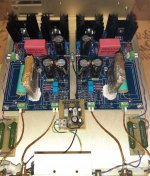
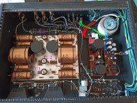
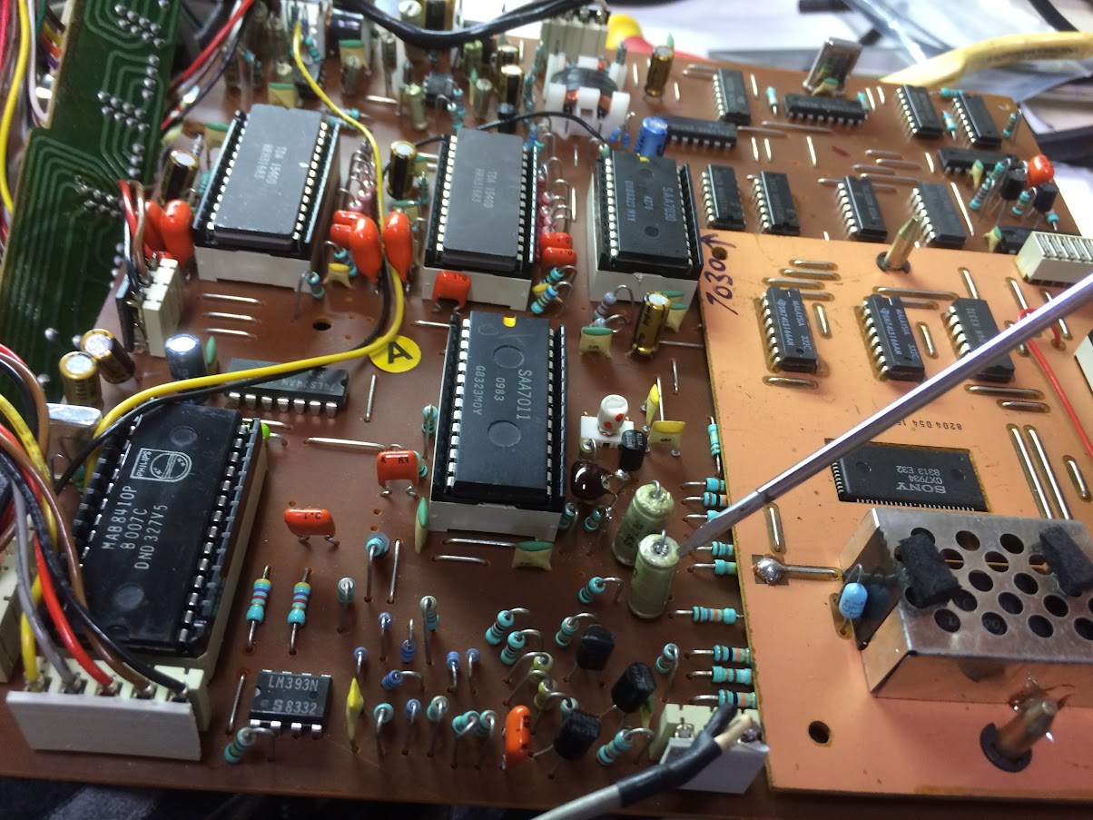
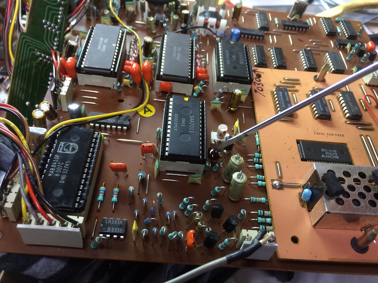
This is for the SONY decoder board, the Philips board is described below.

Capacitors 22nf near the SAA7011 are nice big RF foil antennas, degrading the RF. Pull these out and swap them around (reverse the polarity) putting the high impedance on the inside where it should be. This is easy 5 minutes work.

Solder a cap (I used a 8.2pf mylar) to the top of the resistor (part 3552) next to the de-modulator SAA7011 on one leg(this also goes to pin 13 of the SAA7011) and the other leg of the cap to the cap (part 2655) that goes to the SONY daughter board..

Almost there... you might have to decouple the clock a tiny bit, maybe one or two turns anti-clockwise. This is the white screw thing next to the SAA7011. Be careful the screw thread is weak. Some SONY boards use a mismatch of components. If this is the case the cap can be soldered on the track side of the board.

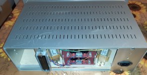
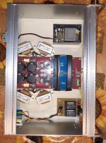
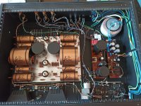
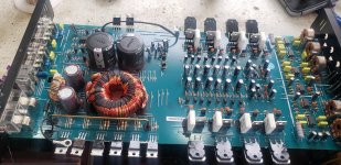
This is for the Philips board, 2 bottom pictures:
This mod would be interesting to many owners of these CD players, not just the Marantz CD73 but Philips CD300, Marantz CD44, 74 ect. Pretty much any identical chipset.
Again 22nf foil Capacitors near the SAA7011 need swapping around (reverse the polarity) as described above. Yellow arrow.
Inside this Philips CD303 there is a resistor with a ferrite bead next to the 7010 Decoder. You need a 220pF cap to go from this resistor (not the bead side) and to RF ground.
Have a look at mine, there was a nice place to put it that makes it look factory. Red arrow.
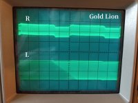
This is where you play a CD with the top open and IF NEEDED carefully decouple the clock one or two turns anti-clockwise (green arrow). My suggestion is find a CD-R that is scratched and had no chance of playing before and put it in, when playing decouple the clock to improve playback. When satisfactory stop playback then press play. If the CD wont track initially then you have decoupled too much. Screw it back half a turn at a time and press stop and play again. Once it plays satisfactory then test the player with proper store bought discs to ensure all is good.
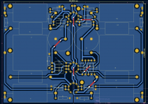
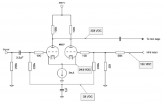
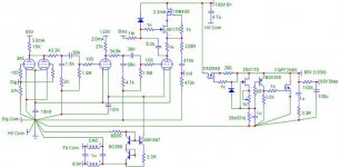
The second last picture shows the block diagram of the decoder board and the red arrows show the location to connect the capacitor. This will mainly help those who want to adapt this to a player that is not a CD73 or CD303.
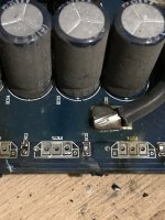
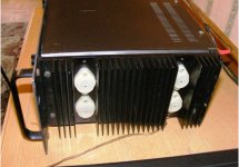
The Last picture is a close up view of the Philips decoder board for easier reference. The Blue arrow shows the electrical connection of the capacitor.

While you're there why not a recap? I prefer Nichikon fine gold series. Especially the two that pass the audio to the OPAMPS. I have also found decoupling the DACs with 100nf WIMA caps to be an improvement also....

Hope this helps others enjoy the glory of these 14bit(noise shaped) players! Feel free to comment on results. 🙂

PYLsgWPPKA7cXUf4l5qmNOfuRmV0diSriVZjgfl82Tz6-cUgzI6z2GH6-xWZd1a8KIJ9hsHIJMIKCOaPgvJtLwXhuvWpwl4JCK_UIaCIMmWNFdakJraPquDJEN1CPMIKggtHclci=w1204-h903-no

BsSLy91KWhxw8visBNJpg3aF6x7M5y0ECG7XPwBboyI-6fFsWpHlG0ZhAUDy-MrZ5aHOXsDlx6PCHuEr1JW2zCVHKVJrtRSrs9zFc3VGxcSf4iY21NVRiNHce2kisi5YIj3AbSqZ=w1204-h903-no

9Qg7W9rTPui3j47031bHyuL9DxxXFMfBg8gPelpnCH-14XXzH_dxtX4S19GOQJyK9tbfOGh3wedfirNVN8X4DhNBmxoU8ms8XN5lbHF1AlF_W0W_vq9TbmZblpvGvrkQ88w1QQ_O=w1204-h903-no
597S7YS4Gq0emauRJXGswxwUrs0rAvhKk_HrWtNZF-Ynv05RZHtBA3XszGxZf0J1trWK6YBRSDXiSU6tDLSLoK2nGxY-vPFBhefOcZelTQ2FqUEIh1iktJj4ADr81lmQkguhoBCamfSRhU6S5PXkGaHDDNJoNv9yOXm7eImosiLaM88GzyYcUrIKpK2MZtBXdv3ECyDb7RcXB7zvIMoDNrzUOzD98Y88jDFgSBCMzg9CSlZyOY7ehsQvjdPqxXfReUb_7or-ywWy31XaHEPvu6EVBnA1a2PJ2P6acVeUfQVBovSTi-MpGCxdwhz4BWIRqlrQNdHvspe9-Sz0F6kgo2qggkqmOhWsu0fqwuqwN6Iw0pEIL-oBlJUrQq2SHq-hxnoZt4IKGXoe6p0SVMmU7p-6L55JgjvXvRajTWMPuIrfoy8GD_i0AmGQRIioSBJ1Zoe61sOPhP1Q3MkOmEnhd6qT2i9VGiOWLWXH4-GSHS31inOuzOw11PH1MGRzomCphHil0Ni6I7M084Wv-SG0kr8jYPDsA5ib8si4_MTDjDRbcx5bqVx0oaAZsjHtmIwpaGgiZlp09rShwNULc5V05b5sqYjVy0KisFeOiRU=w1204-h903-no
An externally hosted image should be here but it was not working when we last tested it.

Subwoofer wiring woes

Hi all,

I recently bought a 300w sub with a broken power board for 15 quid.

I stripped out the power board and the fancy low pass filter, frequency modulator, and volume control board out. Then bought an L7 MOSFET mono power board that supports 300-350 W at 8 ohms as well as requiring 2x 50 V in, this is exactly what the transformer outputs and what the driver requires.

I also picked up a 2M ohm potentiometer for volume control and a 100Hz or so highpass/lowpass filter (i always get it the wrong way round)

because it's a mono out board I'm having a lot of trouble trying to work out how to correctly wire it all?

Any help?

Finlay.


(https://www.ebay.co.uk/itm/221254643945?_trkparms=amclksrc=ITM&aid=1110006&algo=HOMESPLICE.SIM&ao=1&asc=20200818143230&meid=f1091f7470794e6eb76178fa92c156f5&pid=101224&rk=2&rkt=5&sd=224405663394&itm=221254643945&pmt=1&noa=1&pg=2047675&algv=DefaultOrganicWeb&_trksid=p2047675.c101224.m-1 link for power board)
(https://www.hifigear.co.uk/epos-els-subwoofer.html link to sub)

HM100X - Simple 100W power amplifier BR

Hello friends...

Here in Brazil we have a very active diy audio community and due to research I am bringing a new circuit for your enjoyment.

It is a simple audio amplifier, polarized with diodes, with an option for ground suspension of the input signal, 100W, full CCS and differential current mirror

Around here in Brazil we have a lot of bad circuits that are shared on the web that leave DIY people very frustrated when they set up and it doesn't work, so whenever I can I share new tried and tested ideas.

Here are some data measured on a bench

Power: 100W @ 4 Ohm
Sensitivity: 380mV
Input Impedance: 47kOhm
Frequency Response: 10Hz~191KHz @ 3dB
Damping Factor: 995
Simulated THD: 0.02% @ 1KHz (real life measurement will happen soon)


Schematic:
55614953fd630f1dfd0aee6b12d3c523.jpg


PCB:
8efc7c83457d52d50390f04011227f37.jpg


Prototype PCB:
08819ea2c744384156aefe4e6b91dc71.jpg


SCHEMATIC UPDATED: 08/17/21

🙂 I am a happy DipTrace user🙂
  • Like
Reactions: Zohaib Ahmad

Dipole midrange in a 3 way.

I have a three way loudspeaker with a dipole midrange. Is the sound emanating from the rear side of the midrange supposed to be reflected back to the listener or is it ideally supposed to disappear and never be heard by the listener? I asked as my loudspeaker position is not ideal as the left speaker is located where the rear of the speaker opens up to another room, while the right speaker is 2 feet away from the corner. No other positions is available at the moment.
Projects by fanatics, for fanatics
Get answers and advice for everyone wanting to learn the art of audio.
Join the Community
507,709
Members
7,885,350
Messages

Filter

Forum Statistics

Threads
406,092
Messages
7,885,350
Members
507,709
Latest member
tklua