We spent saturday afternoon and evening to align a 5 way horn system using wavelets. I have two questions about the method and the resulting phase measurement.
1. When using wavelets I would assume that you set delays of both speakers so that the center of the wavelets align, not the first sine peak as shown here (From top to bottom: 1. original signal, 2. low-pass filtered with LR4, 3. highpass filtered with LR4, 4. sum of both filtered signals):

The green line IMO shows the correct point to align them, the red line clearly shows that this point in time would be ambiguous as the low pass filtered signal has a longer period length, the high pass filtered one has a shorter period length. only point they sum correctly is if the center of the wavelets are aligned. All in all that should be plausible, the summed signal also shows a 180° phase shift at the crossover frequency as is to be expected from a LR4 filter.
Are my assumptions correct?
2.: Here's the minimum phase as generated from a measurement in REW for the whole system at the listening place (grey: phase, axis on the right - purple: SPL, axis on the left):

I thought that each of the 4 LR4 crossovers would show a 360° phase shift around the crossover frequency? Why does the resulting phase appear to be almost flat from 20Hz to 20kHz? Seems that either something is off here ore my assumptions about the 360° phase shift of LR4 summed signals are incorrect. OTOH as I pointed out the top graph clearly shows the 180° phase shift at the crossover frequency for the summed signal. I'm a bit puzzled here. Maybe I misunderstood what the term "minimum phase" really means, would these phase shifts from the LR4 filters not show up in the minimum phase plot?
1. When using wavelets I would assume that you set delays of both speakers so that the center of the wavelets align, not the first sine peak as shown here (From top to bottom: 1. original signal, 2. low-pass filtered with LR4, 3. highpass filtered with LR4, 4. sum of both filtered signals):
The green line IMO shows the correct point to align them, the red line clearly shows that this point in time would be ambiguous as the low pass filtered signal has a longer period length, the high pass filtered one has a shorter period length. only point they sum correctly is if the center of the wavelets are aligned. All in all that should be plausible, the summed signal also shows a 180° phase shift at the crossover frequency as is to be expected from a LR4 filter.
Are my assumptions correct?
2.: Here's the minimum phase as generated from a measurement in REW for the whole system at the listening place (grey: phase, axis on the right - purple: SPL, axis on the left):
I thought that each of the 4 LR4 crossovers would show a 360° phase shift around the crossover frequency? Why does the resulting phase appear to be almost flat from 20Hz to 20kHz? Seems that either something is off here ore my assumptions about the 360° phase shift of LR4 summed signals are incorrect. OTOH as I pointed out the top graph clearly shows the 180° phase shift at the crossover frequency for the summed signal. I'm a bit puzzled here. Maybe I misunderstood what the term "minimum phase" really means, would these phase shifts from the LR4 filters not show up in the minimum phase plot?
We spent saturday afternoon and evening to align a 5 way horn system using wavelets. I have two questions about the method and the resulting phase measurement.
1. When using wavelets I would assume that you set delays of both speakers so that the center of the wavelets align, not the first sine peak as shown here (From top to bottom: 1. original signal, 2. low-pass filtered with LR4, 3. highpass filtered with LR4, 4. sum of both filtered signals):
View attachment 1039100
The green line IMO shows the correct point to align them, the red line clearly shows that this point in time would be ambiguous as the low pass filtered signal has a longer period length, the high pass filtered one has a shorter period length. only point they sum correctly is if the center of the wavelets are aligned. All in all that should be plausible, the summed signal also shows a 180° phase shift at the crossover frequency as is to be expected from a LR4 filter.
Are my assumptions correct?
Hi, looking at the wavelets, my take is #1 the original signal is pol+. And #2 with 24LR lpf, and #3 with 24 LR hpf, are also pol+.
Looking at the green timing line on #1, it's not at the center peak of the burst, so it looks like there is a constant time delay shift with the hpf and lpf in place, and not a 180 degree phase shift (which would be a change in pol).
With a LR4, that has an180 degree phase shift at xover freq, it will still measure pol+....... with a positive central wavelet peak
I do think it is correct to time align the center of the burst waveforms....like you say, they have different periods.
Caveat: I don't have a tremendous amount of experience with wavelets, but i'm largely confident in all that.........
2.: Here's the minimum phase as generated from a measurement in REW for the whole system at the listening place (grey: phase, axis on the right - purple: SPL, axis on the left):
View attachment 1039101
I thought that each of the 4 LR4 crossovers would show a 360° phase shift around the crossover frequency? Why does the resulting phase appear to be almost flat from 20Hz to 20kHz? Seems that either something is off here ore my assumptions about the 360° phase shift of LR4 summed signals are incorrect. OTOH as I pointed out the top graph clearly shows the 180° phase shift at the crossover frequency for the summed signal. I'm a bit puzzled here. Maybe I misunderstood what the term "minimum phase" really means, would these phase shifts from the LR4 filters not show up in the minimum phase plot?
And This is a 5-way? With four LR4's in place? It appears you have to be using linear phase LR4's?
Nice looking phase trace!
They dhould not have different periods. But the filtering removes the higher peaks. Which are cenetered only for the middle one, so the result should be the same. I would still try to match the zero crossings. With lowest overall error.
there is a glitch near the end. You know what that is?
there is a glitch near the end. You know what that is?
I know nothing about REW and almost nothing about wavelets, but minimum phase usually means the least possible phase shift to get a causal filter with a given magnitude response. When you sum the outputs of a Linkwitz-Riley filter, with sign inversions where appropriate, the result is not minimum phase.
They dhould not have different periods. But the filtering removes the higher peaks. Which are cenetered only for the middle one, so the result should be the same. I would still try to match the zero crossings. With lowest overall error.
Surely can agree with higher peaks when summed, vs low-passed or high passed.
Here is 6.5 cycle Hann burst 640 Hz, both sides of a LR24 crossover summed together.
Vertical goes off the scale, where next two with high pass and low pass show the drop in amplitude.
Next is with the 640Hz LR24 high pass in place.
Note the scope cursors are in the same places, with the same time span 7.04ms between cursors, across the same wavelet zero crossings.
The high passed capture shows less time across the burst than the full spectrum capture above.
Now for the low passed burst.
Note that it is longer than the full spectrum.
So comparing the high passed to the low passed, the wavelets overall period clearly gets longer with the low passed.
Aligning the central peaks, and ignoring zero crossings, has been the way to go ime.
Hey efluon, my apologies.....i think you are correct about aligning starting zero crossings.
It just hit me that the traces i posted are saying that...
I set the scope cursors for the burst into the full range signal, and did not move the cursors for high pass and low pass.
Well, the only part of the three bursts that stayed time aligned is their first zero crossings.
Thanks man!
Seems the stretching and shrinking of the entire wavelets which low passed and high passed, as well as the central peak timing shift.....when combined equal the full-range signal wavelet period (and average kinda). As well as moving central peak in an averaged middle time location from first zero crossing.
EDIT: ok everybody pls ignore all i've written....got my head twisted up now, thinking about how the scope can't help but trigger at zero start, and make that look like alignment. So I'm back to peaks like i've done for acoustic speaker testing. These were straight electrical.
Sorry for the whipsaw.....been simultaneously preparing to go to neighborhood funeral....rushing too much... My bad...
Last edited:
Ok, my head is back on i think... first reply was correct.
The erroneous detour into thinking that we should align the zero crossing of the wavelet's start came from triggering the scope off the measurement channel, instead of the reference channel. Been a while since i fooled with wavelets.
When triggering off the reference channel, measurement delays are seen properly.
Here is a set with cursors unchanged, set to show once cycle of a 640Hz 6.5 cycle Hann burst.
First is with no filter.
Next is with LR24 high pass @ 640 Hz.
Then LR24 low pass @ 640 Hz.
You can see the period defined by no filter is longer than with high-pass in place, and shorther than with low-pass in place.
And central peaks are all aligned.
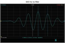
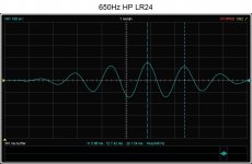
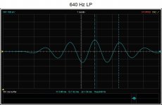
My apologies for the whip-saw confusion earlier.....simply goofed on trigger channel, and forgot a lot of previously learned.
The erroneous detour into thinking that we should align the zero crossing of the wavelet's start came from triggering the scope off the measurement channel, instead of the reference channel. Been a while since i fooled with wavelets.
When triggering off the reference channel, measurement delays are seen properly.
Here is a set with cursors unchanged, set to show once cycle of a 640Hz 6.5 cycle Hann burst.
First is with no filter.
Next is with LR24 high pass @ 640 Hz.
Then LR24 low pass @ 640 Hz.
You can see the period defined by no filter is longer than with high-pass in place, and shorther than with low-pass in place.
And central peaks are all aligned.


My apologies for the whip-saw confusion earlier.....simply goofed on trigger channel, and forgot a lot of previously learned.
OK, seems that my theory about aligning center peaks was correct. You can always generate a wavelet with half a period more length and you get a wavelet that is centered around a zero crossing, which is what ARTA does. Probably because it's better to align on a zero crossing.
I made these examples in audaciy and the glitch was probably me moving things around unwantedly. I carefully redid the whole process and here's the result, no glitch at the end:

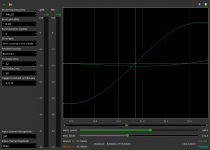
@MarcelvdG : thanks for the explanation of minimum phase, I think I got it now. The question is how do you measure the actual phase response of a multi way speaker system in REW? I fiddled around with the existing measurement data, set a 15ms impulse response window to get rid of most of the room's interaction (should be valid down to around 100Hz) and adjusted the time offset to give me the most sensible looking phase response (not minimum phase). But that procedure is a) painful and b) really really feels wrong! Here's the result:

At least now the "wiggles" in he frequency response somewhat correlate to "wiggles" in the phase response...
Any suggestions?
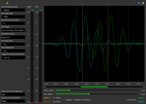
PS: small teaser, I'm working on integrating the wavelet measurement support into Pulsaudio Crossover Rack. Will be released once I can test it on my 2 way speakers, for now only digital loopback testing as my amps are not in my flat and will be back next weekend. Btw. These wavelets have 6.5 periods with a blackman window and thus are centered around a zero crossing.
Don't think that's correct to say that 180° of phase shift is polarity inversion. Most of the mixing consoles also label this wrong where they actually have an invert switch but the name it "phase". IMO 180° of phase shift of a filter corresponds to half a period of delay, but only exactly at the filter's cutoff frequency.Looking at the green timing line on #1, it's not at the center peak of the burst, so it looks like there is a constant time delay shift with the hpf and lpf in place, and not a 180 degree phase shift (which would be a change in pol).
I made these examples in audaciy and the glitch was probably me moving things around unwantedly. I carefully redid the whole process and here's the result, no glitch at the end:
@MarcelvdG : thanks for the explanation of minimum phase, I think I got it now. The question is how do you measure the actual phase response of a multi way speaker system in REW? I fiddled around with the existing measurement data, set a 15ms impulse response window to get rid of most of the room's interaction (should be valid down to around 100Hz) and adjusted the time offset to give me the most sensible looking phase response (not minimum phase). But that procedure is a) painful and b) really really feels wrong! Here's the result:
At least now the "wiggles" in he frequency response somewhat correlate to "wiggles" in the phase response...
Any suggestions?
PS: small teaser, I'm working on integrating the wavelet measurement support into Pulsaudio Crossover Rack. Will be released once I can test it on my 2 way speakers, for now only digital loopback testing as my amps are not in my flat and will be back next weekend. Btw. These wavelets have 6.5 periods with a blackman window and thus are centered around a zero crossing.


I can't help you much, as I know nothing about REW and almost nothing about wavelets.
I don't know if this helps, but what I can tell you is that the phase response of the sum of the low-pass and high-pass outputs of an n-th-order Linkwitz-Riley filter, with inversions where appropriate, is the same as the phase shift of just the n-th-order Linkwitz-Riley high-pass or just the n-th-order Linkwitz-Riley low-pass. It's also the same as twice the phase shift of a Butterworth filter with order n/2.
A Linkwitz-Riley low-pass or high-pass is minimum phase, unlike the sum of both. (The sum has a flat magnitude response. You can also obtain a flat magnitude response with a short straight wire with no phase shift at all. Hence, the phase shift of the sum of the outputs goes beyond minimum phase.)
Last edited:
Aligning wavelets or filtered IR's (which behave much the same) to the central peak is what works with synthetic impulses.OK, seems that my theory about aligning center peaks was correct.
REW has an alignment tool built in. Under ALL SPL and controls. You can visually see the phase and frequency alignment from combining two measurements with a given amount of delay. It will also calculate a delay for phase alignment by selecting a frequency on the graph and clicking one of the alignment options.
For all of these to work properly you need to have a time reference either from a hard wired loopback, or use the acoustic timing reference. Manually removing the time of flight delay can work too.
Minimum phase in REW is always generated. When it is there will also be an excess phase created which shows the non minimum phase parts of the measurement. It is very difficult to keep room influences out of in room measurements, using a frequency dependent window is probably the best way to try and get a look at the phase response of a speaker from an in room measurement.@MarcelvdG : thanks for the explanation of minimum phase, I think I got it now. The question is how do you measure the actual phase response of a multi way speaker system in REW? I fiddled around with the existing measurement data, set a 15ms impulse response window to get rid of most of the room's interaction (should be valid down to around 100Hz) and adjusted the time offset to give me the most sensible looking phase response (not minimum phase). But that procedure is a) painful and b) really really feels wrong! Here's the result:
If this is something you want to do often then measuring with a timing reference will help and a frequency dependent window can be automatically applied with an option in the settings.
Holm impulse is another option as that can leave the soundcard open during subsequent measurements to get a time lock without a loopback.
Some information here amongst other places
https://www.diysubwoofers.org/misc/holmimpulse/ta.html
OK, seems that my theory about aligning center peaks was correct. You can always generate a wavelet with half a period more length and you get a wavelet that is centered around a zero crossing, which is what ARTA does. Probably because it's better to align on a zero crossing.
Cool, we're all together now.
Don't think that's correct to say that 180° of phase shift is polarity inversion. Most of the mixing consoles also label this wrong where they actually have an invert switch but the name it "phase". IMO 180° of phase shift of a filter corresponds to half a period of delay, but only exactly at the filter's cutoff frequency.
Yeah, so many folks erroneously use phase, when polarity is the correct term (for 180 degrees of phase inversion across the spectrum.)
I've never heard of what you speak....."180° of phase shift of a filter corresponds to half a period of delay, but only exactly at the filter's cutoff frequency."
That sounds like a simple fixed delay of 1/2 period of the xover frequency. If so, what possible value could that have?
@MarcelvdG : thanks for the explanation of minimum phase, I think I got it now. The question is how do you measure the actual phase response of a multi way speaker system in REW? I fiddled around with the existing measurement data, set a 15ms impulse response window to get rid of most of the room's interaction (should be valid down to around 100Hz) and adjusted the time offset to give me the most sensible looking phase response (not minimum phase). But that procedure is a) painful and b) really really feels wrong! Here's the result:
At least now the "wiggles" in he frequency response somewhat correlate to "wiggles" in the phase response...
Any suggestions?
PS: small teaser, I'm working on integrating the wavelet measurement support into Pulsaudio Crossover Rack. Will be released once I can test it on my 2 way speakers, for now only digital loopback testing as my amps are not in my flat and will be back next weekend. Btw. These wavelets have 6.5 periods with a blackman window and thus are centered around a zero crossing.
Fluid gave some great pointers as always.
I'd add and suggest starting with REW on the top two drivers in your system to master the process of time and phase alignment. Once you do that for the top two sections, continue downward in iterative fashion.
Lock the delay time of the section that measures most distant, and add processor delay to the closer driver until alignment is reached.
The REW Alignment tool mentioned by fluid will help do this. Or an even easier method, is to simply use the delta in timing measurements vs loopback.
This works very well for any sections mid-range and up.
It gets harder to get accurate repeatable timings vs loopback, as frequency decreases. But fortunately small timing errors cause less time and phase misalignment as wavelengths increase. That's why it's good to start up top, where some certainty can be established to reference timings from..
I'd also suggest to ditch wavelets for alignment until you get down to subwoofer to low integration.
And ditch them even then if you are getting consistent time vs loopback after filters are in place.
The long practiced phase trace overlay method is more foolproof in its simplicity, and it's easy to bank on wysiwyg.
Wavelets help when time vs loopback measurements are lacking repeatability....and that usually only becomes the case low in freq.
Likewise, filtered impulse response aren't needed for alignment, and suffer from needing to match their closest 1/3 octave spacing to the intended xover freq.
KISS (phase trace overlay) works.... ime/imo !!!!
Sorry, no pictures, it's not my system and the owner does not want pictures posted.Did I read 5 way horn system? Any pictures?
Thanks for the explanation, no I think I got it. Now it makes sense why you would want to calculate min. phase - to see excess phase, which is a very nice thing to have. Experimented with that yesterday evening. Also thanks about the hin with the automatic application of frequency dependent windows, very nice feature as well!Minimum phase in REW is always generated. When it is there will also be an excess phase created which shows the non minimum phase parts of the measurement. It is very difficult to keep room influences out of in room measurements, using a frequency dependent window is probably the best way to try and get a look at the phase response of a speaker from an in room measurement.
If this is something you want to do often then measuring with a timing reference will help and a frequency dependent window can be automatically applied with an option in the settings.
What I said was probably misleading, what I meant is that if you send a signal with exactly the cutoff frequency through a LR4 filter it gets delayed by exactly half a period. Other frequencies of course experience other delays varying from 0° to 360°.I've never heard of what you speak....."180° of phase shift of a filter corresponds to half a period of delay, but only exactly at the filter's cutoff frequency."
That sounds like a simple fixed delay of 1/2 period of the xover frequency. If so, what possible value could that have?
On your other notes:
Interestingly using wavelets it was no problem to align drivers with wavelets even at the lowest crossover frequency which in our case was 164 Hz. We began with that and worked our way up because the woofer had 0 delay and all the other drivers had more than that so it was simple to enter the delay values into the DCX2496.
I will try to find that alignment function in REW you mentioned and have a play with that as well. What I liked about the wavelet approach is that it was relatively easy to do remeasurements after changing filters in the DCX2496. Should be even easier with my tool because it will tell you the needed delay adjustment right away after setting two markers. With ARTA we had to calculate the delay by hand.
@everybody: Thanks for all the comments and suggestions! It's always nice to have a place to go to when you're stuck or your brain just does not want to produce any meaningful new ideas
This seems to be a matter of taste. I had the same opinion at first but now I think aligning at a zero crossing is more precise.
If the question was regarding the wavelet extension of my software - it will be able to do both, there's a combobox where you can select the wavelet type to be generated.
If the question was regarding the wavelet extension of my software - it will be able to do both, there's a combobox where you can select the wavelet type to be generated.
Hi Kevmoso & Tfive,
Yeah, either zero crossing for integer cycles, or central peak for half-cycles works fine.
I tend to like the half-cycles because their is mirror symmetry around the center Y-axis.
Whereas with integer cycles, there is symmetry around the Y-axis, but the sides are inverted to each other and it makes it harder for me to determine where center is for longer busts (5 or more cycles).
ARTA also has a pretty neat triangle burst that's easy to read.
Tfive, what software are you using?
- Home
- Loudspeakers
- Multi-Way
- Questions regarding wavelets and phase measurements