what is recomended PCB tracewidth...

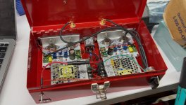
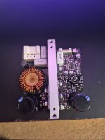
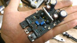
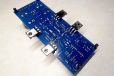
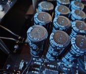
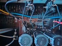
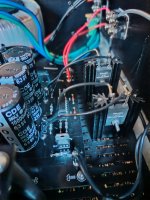
I building a 25W Class A amp using TIP2955 & TIP3055, using KiCad.
powersupply is +/-25.4V
The schematic is done and i now started with the actual PCB.
I now try to fix "netClasses" and atuck with the PWR & OUTPUT net.

When i asked both CoPilot & chatGPT about the trace their answer was:
"
For a current of 10A, a trace width of approximately 200 mils (5.08 mm) with 1 oz/ft² copper is typically recommended3
.For a current of 15A, you might need a trace width of around 300 mils (7.62 mm) with 1 oz/ft² copper3

."
Well, sound great, but the space between the pins are less thatn that. How to solve tthat ?

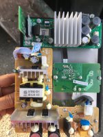
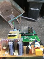
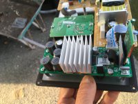
Acoustat TNT 200 amp oscillating

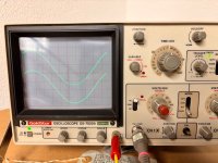
Anyone have any experience with this amp oscillating? I can see it at the input and output. A 10K load and oscillation returns.
I short the input and oscillation goes away. Hard to tell since it could be coming from feedback loop via the output. I think Q1/Q2 FET is bad since it appears these have been replaced with a single package unit and the short to ground at input makes the oscillation null at output.
Some diodes were removed as a mod(Roy Esposito's mods), not sure if these mitigate oscillation or not. Also, C6,C7 look like different parts compared to left channel but are .1uf parts, these tie mosfet drain to gnd at output.

Link to Schematic

Rogue Cronus Magnum II Hum

Hi everyone,

I purchased a used Rogue Cronus Magnum II last fall. The amp is in excellent condition, was available about an hour away from me, and I got it for a couple hundred less than they typically sell for. I am new to tubes and wanted to try something modern with a pair of vintage Altec 604-8Gs I picked up last year. I had a feeling the Rogue might not be the best match for those speakers, but I decided to take a chance on it based on the rave reviews this amp receives online. I also liked the fact that it had a phono stage, balance control, and a remote, which seems rare with tube amps. If it wasn't a good match, I figured I could resell it easily since I was getting it for a fair price.

Well, as soon as I connected it to my speakers I heard a hum that was audible from 20 feet across the room. I had previously tried three different amps with the Altecs including a vintage Yamaha CR-420, a more modern Yamaha RX-797, and a vintage Scott LK-72-B tube amp, and never noticed any hum with those amps. The Scott was on-deck for restoration, and that's another reason why I bought the Rogue. To use while I was working on the Scott.

I noticed speaker hum was mentioned in the Trouble Shooting section of the manual and it said "If hum can be heard from more than a few inches from the loudspeaker, there is probably a ground loop. If this fails to cure the hum, call customer service at Rogue Audio for further advice." I disconnected everything from the amp except the speakers and plugged it into a dedicated 20amp circuit, but the hum was still the same. I also tried using a cheater plug to disconnect the ground prong, but that made no difference either.

I emailed Rogue and they said my Altecs were very efficient and used a large woofer. So they would expect some level of hum, but they also asked me to mute the amp and listen for transformer hum. I did that and could hear the transformer from several feet away. So they said the bridge rectifier may be on it's way out and it would be a good idea to replace it. I did that at a cost of about $70CAD, but it made no difference to either the transformer or speaker hum.

I also tried the amp with a pair of vintage Celestion 332 speakers in my basement system. They are considerably less efficient than the Altecs, around 85-86dB by modern standards I believe, but I could still hear the speaker hum from across the room. I measured the hum with a Decibel Meter on my phone and it said the frequency was around 120Hz

I really want to like this amp, but the hum is unacceptable to me. I have also finished restoring the Scott and it sounds great and is dead quiet in comparison. So I would like to sell the Rogue, but I can't sell it in good conscience without mentioning the hum and transformer buzz.

Rogue ran out of ideas and said I could send it back to them for service, but that would cost at least $150CAD one way and if the transformer needs to be replaced that would be $400USD plus return shipping. I have also read a few forum posts from other people who have experienced similar issues with hum and transformer noise with this amp (wish I'd seen those before buying). So I'm also worried that if I ship it back, they might say it's operating within factory specs and return it to me. Then I'll be right back where I started, but I'll be out 300 bucks for shipping.

I did listen to the amp before I bought it, but I have to admit I didn't listen for things like hum or transformer buzz with no music playing. LESSON LEARNED! I also spoke with the seller and he assured me he never had any problems with hum, but his speakers were much less efficient.

Oh, I also purchased a couple 12AU7 tubes to try in the preamp socket, but none of them made any difference. One was an RCA Cleartop and two others were vintage Baldwin organ tubes that the seller said are factory selected to be ultra-quiet non-microphonic.

So now I have an amp I don't want to listen to and may have trouble selling. Does anyone have any suggestions at all for any other troubleshooting or diagnostics I can do? I purchased an oscilloscope recently, but all I've used it for so far is identifying the outer foil on the capacitors for the Scott.

Sorry for the long post, but I wanted to explain everything I've been through with this amp. This Rogue was one of the most expensive audio purchases I've ever made and it has also been one of the most disappointing. 🙁

Any suggestions would be much appreciated.

Thanks,

Andy

Speaker question

I have a 16 ohm speaker I made using:

1. 2 RCA 12" 8 ohm woofers in series.
2. 1 Goodmans Midax.
3. 1 Klipsch KG4 tweeter with series resistor to drop the level and equal 16 ohms.
4. Goodmans 15 ohm 3 way crossover.

I currently use the following 15 watt amp kit to drive the speaker.

https://store.qkits.com/electronic-kits/audio-kits/15-watt-mono-audio-power-amplifier-kit-fk607.html

Noticed at full volume it tended to have issues until I put a 16 ohm resistor in parallel with the speaker input on the crossover, however that's power being wasted.

There any audio transformers with an 8 ohm primary and 16 ohm secondary with a frequency response of 30-20kHz or can I use an audio output transformer that has an 8 and 16 ohm tap?

Also is there a small mono or stereo bridgeable amp that has a 16 ohm output or can I use a small stereo amp that can drive an 8 ohm load with an unbalanced to balanced transformer on the input?

The amp and speaker are used in a screen room at work where I test a unit so the amp cannot be class D due to interference that would cause.

How it's all connected is I have the following Edcor stereo to mono balanced transformer connected to my stereo's tape output which is on my desk about 20' away.

https://edcorusa.com/products/wsm-s...2w-distribution-voltage-matching-transformers

I then have the following Edcor 15k balanced/unbalanced to balanced/unbalanced transformer in a box on the screen room to convert the signal back to unbalanced then it is connected to a feedthrough connection on the screen room which then connects to the amplifier.

https://edcorusa.com/products/wsm-s...-matching-transformers?variant=41117605462203

It isn't possible to feed the balanced signal into the screen room given there are four other feedthrough connectors on the screen room with one in use and the other three not fitting any adapters I have available that could convert to BNC.

Rate my AI crossover for SB monitor. Claude Ai

I've been playing around with Anthropic's Claude which seems very powerful and fairly technical. How does this look as a two way crossover for SB acoustics Satori drivers.

# Advanced Crossover Design

## Driver Characteristics
### Tweeter (TW29BN)
  • Impedance: 4Ω
  • Sensitivity: ~88 dB/1W/1m
  • Recommended Crossover: 3kHz
  • Fs (Resonance Frequency): ~850 Hz

### Midwoofer (MW19P)
  • Impedance: 8Ω
  • Sensitivity: ~87 dB/1W/1m
  • Recommended Crossover: 3kHz
  • Fs (Resonance Frequency): ~55 Hz

## Optimized Crossover Topology
### Revised Design: 3rd Order Asymmetric Linkwitz-Riley
  • Low-Pass on Midwoofer: 18 dB/octave
  • High-Pass on Tweeter: 12 dB/octave
  • Crossover Frequency: 2.8 kHz

### Precision Component Values
#### Midwoofer Network (Low-Pass)
  • L1: 1.5 mH (Air-core inductor)
  • C1: 10 µF (Polypropylene film capacitor)
  • R1 (Pad): 2.2Ω non-inductive resistor

#### Tweeter Network (High-Pass)
  • L2: 0.68 mH (Air-core inductor)
  • C2: 22 µF (Polypropylene film capacitor)
  • R2 (Pad): 3.9Ω non-inductive resistor

## Compensation Components
- Zobel Network for Midwoofer:
- Rs: 5.6Ω
- Cs: 100 µF
- Notch Filter (Optional): Targeting any mechanical resonances

## Phase and Impedance Correction
Code:
                 L1       C1
MW19P +---+---@@@@---||---+
        |   |            |
        R1  |            |
       /\/\ |            |
        |   |            |
        +---+------------+
                |
                | Crossover (2.8 kHz)
                |
        +-------+-------+
        |               |
       L2             R2
      @@@@           /\/\
        |             |
       C2             |
        ||            |
        |             |
TW29BN  +-------------+

## Impedance Correction Zobel
        Rs
TW29BN +/\/\---+
               |
              Cs
               ||
               |
              GND

## Optimization Goals
1. Flat frequency response (±2 dB)
2. Smooth phase transition
3. Minimized off-axis response irregularities
4. Controlled power response

## Recommended Measurement Procedure
1. Near-field measurement
2. Gated measurement at 1m
3. Verify:
- Frequency response
- Phase coherence
- Impulse response

## Critical Component Selection
- Capacitors:
- Polypropylene film
- Low ESR
- Tight tolerance (±2%)
- Inductors:
- Air-core or Copper/Aluminum foil wound
- Low DCR
- Tight tolerance
- Resistors:
- Non-inductive
- Metal film
- 1% tolerance

## Performance Expectations
  • Usable Frequency Range: 45 Hz - 20 kHz
  • Sensitivity Matching: Within 0.5 dB
  • Impedance: Nominally 8Ω (min 6Ω)

For Sale Tamura A-8713 Line transformers / SUT

Pair of Tamura A-8713

Can be used as line output transformers: 20K-600 / 20ma. There are 2 primary and 2 secondary, so multiple combinations possible

Or vice versa as step-up, with e.g. ratio 1:5.6 or 1:11

SOLD

Attachments

  • IMG_4382.jpeg
    IMG_4382.jpeg
    983.6 KB · Views: 53
  • IMG_4383.jpeg
    IMG_4383.jpeg
    816.5 KB · Views: 54
  • IMG_4384.jpeg
    IMG_4384.jpeg
    918.9 KB · Views: 45
  • IMG_4385.jpeg
    IMG_4385.jpeg
    830.6 KB · Views: 50

Midbass driver vibration dampening schemes

Over the years I've discovered the benefits of chassis vibration dampening when mounting midbass / midrange drivers on most types of baffle surfaces.

The largest benefit I've observed was by fully isolating the driver chassis from the baffle structure using viscoelastic materials as well as other elastomers and polymers. The latest project I'm planning to do this with is on my large 3 ways using the Eminence Canna-bass CB3012-N8 woofer /midbass, Bliesma M74A and T34B.

Some of the lighter weight cast frame drivers can be prone to resonances due to chassis flex. This somehow needs to be supressed when using the driver for more critical hifi applications. You can observe the main effects of these resonances by observing the impedance sweep of the chassis in free air vs clamped in a baffle. The resonances are usually found in the midbass region between 200 - 800 hz in form of smaller impedance peaks. The trick is isolating them from spider resonance and radial cone modes occurring in a similar region.

I purchased some supplies online and from a local hardware store. I chose #10-32 screws with a shallow allen head for the Eminence 10s which fit perfectly in the recessed chassis bolt hole pockets. I'm using 1/4" OD, 3/16" ID flanged grommets (typically used to isolate hoses passing through metal from rubbing). These fit perfectly around the 10-32 screws and locate the driver on the baffle flange. A small washer under the screw head will be needed to keep the underside from, twisting the grommet while tightening the driver down. Of course I'll be using either a strip of neoprene or sorbothane between the chassis and baffle flange. This will fully isoate the chassis from the baffle surface.

Attachments

  • 20250307_103105.jpg
    20250307_103105.jpg
    295.3 KB · Views: 49
  • 20250307_103149.jpg
    20250307_103149.jpg
    305 KB · Views: 49
  • 20250307_103159.jpg
    20250307_103159.jpg
    414.8 KB · Views: 49
  • 20250307_110145.jpg
    20250307_110145.jpg
    451.2 KB · Views: 52
  • 20250305_084951.jpg
    20250305_084951.jpg
    340.6 KB · Views: 50

Hello everyone!

Hello everyone,
I have been registered since a long long time ago, I wanted to make a post, but I was asked to introduce myself as a new member to be able to post again.

So I am introducing myself as an electronic hobbyist doing restorations for my pleasure and also by loving those iconic vintage audio gears as an audiophile as well.
I am restoring "as new" those gears such as R2R's, amplifiers, preamps and Loudspeakers.
I have some skills in electronics, but also as a full DIY modeler I am able to work wood, do wood veneer cabinets with High gloss varnished finishing, rebuilding faceplates with graphic illustrating done with computer work by rebuilding original layouts.
*Sharing some pics of some work I have done on those HiFi gears from my collection; I have fully restored and also upgraded these beautiful audio icons...


IMG_0952.jpeg
IMG_0954 2.jpeg
IMG_1561.jpeg
IMG_1806.jpeg
IMG_1198.jpeg
IMG_8525.jpeg
IMG_8536.jpeg
IMG_9715.jpeg
IMG_2017 copie.jpg
IMG_2066.jpg
IMG_9712.jpeg
IMG_2303.jpeg
IMG_2248.jpeg
IMG_2430 2.jpeg
IMG_2423.jpeg
IMG_1447 2.jpeg
IMG_1429 2.jpeg
IMG_9273.jpeg
IMG_9463.jpeg
IMG_9504.jpeg
  • Like
Reactions: krivium

807 tube amplifier build

As I just like the look of the old 807 tubes I decided to build a amplifier based on the 1930s 807 type.
As I recently finished the build I thought I would post the results in case it was of interest.


Is this finest sounding amplifier ever built? No not even close but for the first beam power tube technology of the 1930s it does perform surprisingly well.
Total THD at 1 watt is below 0.05% and at 1Khz and below 0.2% at 40 watts output. At 20Khz THD is below 0.4% at full power and under 0.05% at 30HZ again at full power.
At 1 watt the THD is mostly second harmonic, however it transitions to mostly third harmonic above about 5 watts.

The 807s plates run at 510V into a P-P impedance of 6600 ohms , with fixed bias and regulated screens set to 350V.
The screens are provided with a portion of the plate AC signal voltage in a variation on the classic UL mode of operation.
Running the 807 in UL mode really helped tame some of the 807s bad habits and greatly helped with stability in general.
There are also large ferrite sleeves on each plate lead , 1K screen resistors and 100 ohm grid stoppers.
The 350V on the screens may seem high as the tubes are rated at only 300V but that is in pentode mode.
In triode mode the screen can be run to 400 volts according to some data sheets.
The way I am running the 807 screen the 350V on the screen is modulated by the plate AC voltage and so drops to about 275 volts at minimum plate voltage where
maximum screen current occurs.
This greatly limits the screen power dissipation at full power while still providing good plate current and drops the output tube distortion to about 1/2.

I chose to drive the 807s with a cathode follower for two reasons. First it allow for a low DC impedance on the 807 grids
This stabilizes the bias current in the presence of any grid leakage when the tubes are run hard.
Second it allows a smooth transition into class AB2 at high power instead of clipping and blocking distortion that most class AB1 designs enter at zero grid volts.
This provides extra output power and a fast recovery for any clipping. Class AB2 is entered at about 25 watts output and extends power to 40 watts.

The cathode follower is driven by a LTP pulled to a -120V rail by a high value resistor.
The cathode resistor does not provide the perfect balance of a current source but the small error is easily trimmed out with a POT during amplifier setup.
As a balance adjustment is helpful for correcting output tube gain errors the adjustment is needed anyway.
I stuck with a resistor as it is simple and bullet proof and importantly low in distortion at 20Khz where many current sources have increased THD and loss of impedance do to speed issues within the current source.


The input stage is a simple pentode amplifier using a 6AK5. Nothing fancy here but the 6AK5 can provide a lot of low distortion gain.
The 6AK5 is direct coupled to the LTP to limit phase shift in the amplifier and only one coupling capacitor is used between the LTP and the cathode follower.
The screen is bypassed by a 100nF capacitor to the cathode to increase gain. The capacitor value is chosen to insure low frequency stability by providing a shelving in the low frequency gain. Further LF phase compensation is proved by a large value cathode capacitor, resistor network.
Feedback is injected into the 6AK5 cathode from the 8 ohm speaker tap.
The result is a stable amplifier that is perfectly happy and stable at high and low frequencies with no load on the transformer secondary.

All rails are regulated except the 510V B+ on the 807 plates.
This provides a lot of added margin in the output tubes by stabilizing all voltages and currents and makes the amplifier mostly immune to line voltage variation.
Hum is banished as well.
The cost of regulated rails is complexity, there is no denying it.
Regulated rails are great for performance and stability but exact a price in complexity.

Here are some pictures of the newly finished build.
It is pretty busy inside and there is some wiring cleanup still to go.
I also posted the circuit diagram.

Now there will be a burn in for a few weeks providing background music in my lab.

Attachments

  • 3215AB10-SCH.PDF
    3215AB10-SCH.PDF
    206.4 KB · Views: 223
  • 20250302_172209.jpg
    20250302_172209.jpg
    241.7 KB · Views: 241
  • 20250302_172219.jpg
    20250302_172219.jpg
    276 KB · Views: 222
  • 20250302_172233.jpg
    20250302_172233.jpg
    221.6 KB · Views: 224
  • 20250302_172839.jpg
    20250302_172839.jpg
    382.1 KB · Views: 213

What will you do with your Peerless by Tympahny DFM-2535R00-08?

Thanks to @Mitch311 for suggesting this thread.

Huge thanks to @sheeple for organising the group buy

So, what will you do with your drivers from the group buy?

I intend to try them in my DIY SH50 style MEH horns.

Seen here with BMS4550s

IMG_20240308_162024~2.jpg


They have to reach down to the 5" mids.
They will be used in a hifi setting and not huge volumes, hopefully they will take it..

I have a pair of BMS 4550 drivers for PA🙂

I'm using my Vitavox S2s at the moment, and have made an easy screw in adapter for fast swap over.

Here with the S2 and full driver compliment

IMG_20240629_173351~2.jpg


I'm sure more then just me would love to see your builds and uses.
What's planned and what's on the work bench?

Hi

Hi,
I've signed up to ask for help in restoring an old Philips CD104 CD player. It's a wonderful device and the construction quality is really very impressive, so it would be a shame to leave it nonfunctional.

That's about it.

Attachments

  • 20250123_132835.jpg
    20250123_132835.jpg
    682.6 KB · Views: 27
  • 20250123_133042.jpg
    20250123_133042.jpg
    720.6 KB · Views: 23
  • 20250123_133048.jpg
    20250123_133048.jpg
    836.6 KB · Views: 24

TAD 2402 clone

Hi,

I have always had a 'thing' for the classic TAD 2402 and now it is time to get started. However, the TD-4001 are either difficult or near impossible to source and even a pair of beat-up TD-4001's are pricey these days.

I have read a few comments about people that have had good results using the JBL 2450 with Truextent diaphragms - is this the way to go if I cannot find a pair of reasonably priced TD-4001's? It seems like it matching the horn pretty nicely in terms of exit angle etc.

Was the original fitted with a gasket between the enclosure and the horn to prevent air leaks and how was the horn held in place?

I will probably have Athos Audio do the horns and probably also the enclosures.

Thanks!

/Jeppe

Martin Logan Aerius i crossover upgrades

Hey Guys

So the other day I picked up a used set of Martin Logan Aerius i ESL's in great shape and I have been really enjoying them. I was thinking it might be a good idea to think about replacing the 20+ year old electrolytic caps in the crossovers with something better such as Clarity caps. I'm fairly new to this but know this is popular with conventional style loudspeakers. I'm comfortable working through parts values but I'm not really 100% sure where my time and money would be best spent so I'm here to take in any info offered.

Martin Logan has proved to be extremely helpful and provided me with crossover schematics and a detailed electrical print on the whole speaker. I have not opened these up yet to take a look for myself but plan on doing so this week at some point. I've attached all the electrical info for everyone's viewing pleasure.


PXL_20220130_145104329.jpg


Martin-Logan Aerius i crossover schematic 4WR-page-001 (1).jpg


Martin Logan MLPS104 Aerius_i 240V-page-001.jpg

Another (ultimate?) Behringer mod - what can $50 do to DEQ2496 (PART 1)

Behringer DEQ2496 is well known cheap audio processor, which was on the market for almost 10 years . Now you can find even more impressive devices like made by MiniDSP ot DSPeaker, but they are more expensive too and for some applications are less flexible. DEQ2496 was (and likely still is) considered a best bang for the buck digital processor that packs a lot of goodies - parametric and graphic equalizers, dynamic compressor/expander, dynamic equalizer, limiter, stereo field expander, ADC and DAC with 24/96 sampling. All these features can be used in parallel and stacked on each other. That is why a lot of DIYs use it for things like room correction. But at the same time it is known that it sounds good only when used as purely digital processor bypassing internal ADC and DAC.

I bought one of this devices via Craigslist few years ago with a goal to suppress some modes in my music room. I tried it there between pre- and power amplifier, but felt that it was not transparent enough comparing with the rest of my audio chain. I also tried it between digital transport and preamplifier and felt that it is better works that way, but considering that I use analog sources too, I couldn't really use it. So Behringer went on a shelf, and stayed there for almost two years. Recently I decided to give it another try, this time not in stock form and shape.

But what is exactly wrong with analog to digital and digitral to analog processing in DEQ2496? Several people measured performance of DEQ2496 in analog domain and found it unsatisfactory. One example you can find here: Archimago's Musings: MEASUREMENTS: Behringer DEQ2496. As you can see numbers (other than jitter) do not look too bad. But more serious problem can be found from measurements on this page Behringer Mods - Upgrade DEQ2496, DCX2496, SRC2496 It is clear that DEQ2496 has very high level of IMD at high frequencies. Picture shows that odd order intermodulation harmonics reach -70dB level - that should and is considered very poor for modern device. I did similar series of measurements myself . I used SpectraPlus 5 software and old, but still excellent EMU 0404USB audio interface (Archimago from link above used it too). EMU has distortion level many times less than DEQ2496, thus my results were not significantly affected by its own distortions. Below you can find distortion spectrum for 1 and 10 kHz tones, 19+20 kHz and 60+7000 Hz IMD test signals and silent test. All these tests were done through main analog inputs and outputs of DEQ2496 running at 96 kHz sampling rate. I also added 19+20 kHz loopback test of EMU interface as a reference.

From pictures you can see that Behringer has high level of harmonic and IM distortion for high frequency signals. Worst distortion spectrum can be observed in 19+20 kHz IMD test, with distortion levels more than 0.1% and odd order harmonics reaching -65 dB. There is no surprise that Behringer sounded rather poorly when used with analog inputs and outputs. As a comparison I did another test in digital domain and as expected there were almost no distortion observed. On the surface DEQ2496 uses high quality Asahi Kasei chips which should provide very low distortion. They are commonly used in studio gear 10 times more expensive than Behringer device. Thus if this is not about actual A/D and D/A chips, then it should be analog part, right?

Attachments

  • 1 khz original.jpg
    1 khz original.jpg
    432.2 KB · Views: 2,752
  • 10 khz original.jpg
    10 khz original.jpg
    428.8 KB · Views: 2,666
  • IMD original.jpg
    IMD original.jpg
    437.5 KB · Views: 2,616
  • 19-20kHz original.jpg
    19-20kHz original.jpg
    444.3 KB · Views: 2,605
  • Silence original.jpg
    Silence original.jpg
    414.8 KB · Views: 2,557
  • 19-20kHz EMU loop.jpg
    19-20kHz EMU loop.jpg
    432.3 KB · Views: 535

DEQ2496 V2.5(!) (2017) Recap and Opamp Upgrade

I will be recapping and upgrading the opamps on my recently purchased DEQ2496.

I noticed that the digital board is v2.5. Based on the rigorous work of stef1777 of diyaudio and awdiy.com, I noticed that my board layout was different from the photos and descriptions he provided.

As such, I believe this may be the first DEQ2496 mod featuring the v2.5 board.

The AKM AK5393 ADC has been replaced with a Cirrus Logic CS5381-KZZ and the capacitors around this ADC now include a few 1uF 50V radials which were absent on the previous layout.

See attached photo of the digital board. I have annotated some of my plans, including how I plan to follow stef1777's suggestions to piggyback 10uF 10V OSCONS on some of the ceramic caps. It seems as if there are actually several more candidates for similar piggybacking or outright replacement which I have left without annotation.

I am excited to increase my electrical engineering knowledge as I am an economist by trade so I do have one initial question for the gurus of diyaudio - looking at frequency coefficients, it seems that 50V capacitors have higher (worse?) frequency coefficients versus their 25V cousins (usually on a datasheet you can see both variants side-by-side). I find it odd that there would be 50V caps on this board, especially when it seems this is the first time 50V caps have ever been used on the DEQ2496 (at least on the digital board). Can I use 25V instead? I know this is not a simple question, but perhaps my detailed photo and the experience of this community can help me answer this question.

Thanks!

(I have mostly settled on Elna Silmic II caps for the analog board's 47uF 25V caps, the (ridiculously) more expensive Panasonic OSCONS for the 10uF 25v caps on the digital board, and PPS Film caps for the 1n5, 2n2, and 390p ceramic smds. If I'm feeling sadistic, I may replace some of the 100n and 100p smds as well. There are a few others, for example, stev1777 suggested replacement of C1 10uF 25V on digital board with a 22uF 25V and 2.2uF 50V that I will need to choose as well - <strike>assuming that v2.5 C1 cap is the same as v2!</strike> *there are differences because the ADC is different, see post #12)

I have also included stev1777's awdiy.com picture of the v2 board so you can see the differences (at least some of them).

I'll leave the analog board for a separate post in this thread.

Attachments

  • deq2496_digital_board_V2.5_recap.jpg
    deq2496_digital_board_V2.5_recap.jpg
    360.9 KB · Views: 1,019
  • DEQv2_AKM_caps.jpg
    DEQv2_AKM_caps.jpg
    138.7 KB · Views: 1,059

STK054 Sony amplifier

Dear forum members! STK054 failed in a Sony STR-7025 type amplifier. This type is not available, so a replacement part, STK056, would be installed in its place. In this case, do I need to change something, or do I just solder 056 in place of 054 and it will work? Maybe an idea what can be installed instead? I heard LM1875 could be good for it, I don't know if it requires a big conversion or is relatively simple?

QRD diffuser question

I am doing some sound treatment upgrades to my listening room and plan to build some QRD diffusers. Is there a sweet spot for which prime number to use? I know the diffusers get more involved as the number increases. I kind of like the QRD with 11 wells but I'd like to know more about the major differences and if it's worth higher numbers. My room is about 16 x 30 so it's pretty large compared to many home listening rooms. I'm already doing plenty absorption panels on the walls and ceiling, 8" on the walls and 4" on the ceilings. I can go up to 8" deep for the QRD diffusers which seems to give a pretty wide diffusion range with 11 wells.

Also, is it best to install the QRD diffusers on the wall at first/secondary reflection points?

Thanks,
Milkduds
  • Like
Reactions: EmSuppSW

Home theater subwoofers with UM15-22 drivers and Crown K2 amp

Hi folks,

I have been working in my home theater to replace the Martin Logan Dynamo 1000 sub with diy ones. After a bit of reasearch, I settled onthe Dayton Ultimax UM15-22 which are 15 inch dual voice coil 800W drivers. I have a couple of friends that have pro power amps and I decided to go with a Crown K2 because it has no fan which is great for HT use.

I found a K2 amp in a pawn shop for a good price, but it needed a bit of love so i stripped the electronics and send it for a powder coat. I was not able to take of the face overlay sticker withouth damaging them so I redid the layout and laser engraved some durablack sheets to replace the stickers. After seeing that my friend wanted to do the same so we did the same treatment to his but wil silver stickers. See pictures attached!

Afterwards I ran some simulations with winISD to compare the Sealed vs Ported enclosure. 9cu ft ported tune at 19Hz vs 4.5 cu ft sealed enclosure. It obviously the sealed showed a more promessing response... but what the heck... let's build them both and see how they compare in the real world!

So i did just that and was surprised to see how the results are close to the simulations! The ported enclosure (9 cu ft), although twice the size of the sealed (4.5 cu ft) one, won the contest hands down. The bump arount 45Hz is my room mode that I haven't treated yet...I just need to build a second one and finish them up.

So there it is, hope you enjoy!

Attachments

  • 20181230_225955.jpg
    20181230_225955.jpg
    968.2 KB · Views: 541
  • 20181230_225948.jpg
    20181230_225948.jpg
    982.6 KB · Views: 504
  • 20190102_121810.jpg
    20190102_121810.jpg
    670.4 KB · Views: 471
  • 20190102_121816.jpg
    20190102_121816.jpg
    678.3 KB · Views: 480
  • UM15 Ported vs Sealed simulation.png
    UM15 Ported vs Sealed simulation.png
    59.2 KB · Views: 488
  • UM15 Ported vs Sealed.png
    UM15 Ported vs Sealed.png
    156.4 KB · Views: 262
  • 20181009_001808.jpg
    20181009_001808.jpg
    344.3 KB · Views: 260
  • 20181015_073425.jpg
    20181015_073425.jpg
    381.9 KB · Views: 250
  • 20181125_152422.jpg
    20181125_152422.jpg
    419.6 KB · Views: 239
  • 20181206_192930.jpg
    20181206_192930.jpg
    321.1 KB · Views: 210
  • Like
Reactions: Old School Marantz

Kenwood L08M round 2

Hi
first let me thank @BSST , @Mooly , @pitbul again for all the effort on my previous experience with a pair of Kenwood L08M.

https://www.diyaudio.com/community/threads/kenwood-l08m-circuit-discrepency.400634/

I have another pair which I am working on and need some insight and guidance.

Current Status:

All caps have been replaced (except the main power supply caps)
The 10 ohm and 2.7k 3W resistors have been replaced.
New relay installed
Q25/Q26 installed
R51/R52 installed
all other components installed
D8-D9 Shorted
C17 shorted
Input shorted
Q29/Q30 (drivers installed)
all relays click and dim bulb off.

The not so good news

In this state the base of Q29 and Q30 are both -0.4v, where as I would expect that Q30 should be +ve rather than -ve

I should also add that there is no voltage across R51/R52, or R57/R58 which implies the front end is working as it should.

additionally when the 2SA output is installed- the relays click and the dim bulb goes off, suggesting that the negative rail side is OK,
however when the 2SC is installed, the Dim bulb goes on and no relay click

any help greatly appreciated

Peter

Alternative replacement subwoofer driver needed for VideoLogic Sirocco system

Am a complete beginner with DIY audio, with zero experience, so will probably not have supplied enough info here, but it's a start....

I have a VideoLogic Sirocco system here, on which the sub-woofer driver has disintegrated. The foam surround has fallen apart, as seems to be usual with the Audax drivers used in these VideoLogic systems. I had a pair of the mid-range drivers - also Audax - fall apart in exactly the same way several years ago. Fortunately, managed to find some good replacements units on eBay.

The subwoofer driver in question is an Audax AP170M2.

17cm unit. 6.5" paper cone, polymer chassis. 8 ohms. 45W nominal power. Spec sheet attached here.

The woofer cabinet is 39cm x 20.5cm x 34cm external, with wall thickness of 1.5cm, giving an internal volume of 19.5 litres. The cabinet has no padding inside, and a single front-facing port.

The Audax AP170M2 no longer seems to be available, and given the method of its demise I'm not sure I'd replace it with another one even if I could find one! Those foam surrounds look pretty feeble, as they were on the mid-range units.

Wondering whether anyone has any suggestions or recommendations for a suitable alternative please.

Initial searches have revealed many options, of which 2 might be:-

Visaton W 170 S - 8
https://www.soundimports.eu/en/visaton-w-170-s-8.htm

Dayton Audio DA175-8
https://www.soundimports.eu/en/dayton-audio-da175-8.html

Also found a Dynaudio Esotec MW 162, but that's £150, and probably far too good for the cabinet.

(Also have a pair of Dynaudio BM15A active monitors here, and they are wonderful, but they're not used all the time. The VideoLogic system is the everyday setup connected to my PC).

The searching has made me very aware that I have very little idea of what to look for, or how to assess the likely performance of any candidates. And have zero experience of any of them to fall back on. i.e. how do they sound, and how might they compare with the existing but dead Audax?

Have just watched this video, which I found very instructive on how to interpret speaker specs and graphs. Though he did a good job, assuming that he’s right.

How to Pick The BEST Drivers For Your DIY Speaker Project
Login to view embedded media
But am still at a bit of a loss as to how to decide what to actually buy!

Can anyone chime in with any advice or pointers please?

Thank you.

Attachments

I don't know what I'm doing here... but I like it!

Hello everyone from southern Italy, wandering around the net I often found myself on these pages, I have always been a lover of music and its best reproduction but without excess or fanaticism. I recognize the great value of doing it yourself, but unfortunately I am not capable of it except at very low levels, hence my nickname. I have read dozens of pages (without understanding almost anything) and I don't know... maybe slowly... I will ask stupid, absurd questions, unreasonable requests but this is a world that I like, especially because I don't know it and I love the things I don't know. 😉

Pioneer A-6 amplifier problem

I have this integrated amplifier for ages as an inheritance. Lately the right channel is not working as it should be. I cannot set the bias adjustment as per service manual. It stays at zero (0). The service manual recommends a +/- 31mV. The left channel i was able to set it. On the other hand , I replaced much of the components on the bias circuit section of the amp after finding some faulty components, i.e. opened diodes, signal transistors, pre-drivers, etc. The output transistors are OK since i tried swapping it with the left channel but still exhibits the same fault.

I measured the DC offset voltage with the left channel as zero and the right channel having a reading of 20mV.

What gives? Any help is much appreciated. Many thanks in advance.

pioneer-a6-vbe.png

FM-Stereo-Tuner: Currently vs Vintage Version - e.g. Accuphase T-1200 (DDS) vs. Sequerra Model No. 1

I was recently amazed when I discovered this 5-year-old (pretty new) FM tuner model T-1200 (T1200) from Accuphase:
https://www.accuphase.com/cat/t-1200_e.pdf
https://www.accuphase.com/model/t-1200.html
https://www.accuphase.fr/t1200.htm (good pictures)
https://revolutionturntable.com.au/shop/products/electronics/accuphase-t-1200-fm-stereo-tuner/
https://soundline.co.nz/products/accuphase-t-1200-fm-tuner#mz-expanded-view-698524628483
https://www.stereonet.com/forums/topic/281090-accuphase-t-1200-tuner/
https://www.analog.com/media/en/technical-documentation/data-sheets/ad9864.pdf
It is astonishing to me that FM radio is to be switched off or has already been shut down in some countries (replace by DAB/DAB+)
Interesting to know for me is, what was the motivation on Accuphase to create such a top class FM tuner with DSP technology so as the difference in sound performance compare to old fashion top class device for FM stereo reception like e. g. this unit:

Sequerra Model No. 1
https://sb015eafc300824f1.jimconten... - FM-1 - FM Stereo Tuner (user's manual).pdf
https://skyfiaudio.com/products/the...uner-top-3-ever-made-complete-your-collection
https://www.fidelity-online.de/der-sequerra-fm-1-von-herrn-f-aus-o/

or to similar top class vintage units like K&H FM2002 or Revox B760.

Attachments

  • Accuphase T-1200 front.jpg
    Accuphase T-1200 front.jpg
    39.9 KB · Views: 367
  • Accuphase T-1200 rear.jpg
    Accuphase T-1200 rear.jpg
    41.2 KB · Views: 330
  • Accuphase T-1200 open.jpg
    Accuphase T-1200 open.jpg
    63.7 KB · Views: 322
  • Accuphase T-1200 tuning.jpg
    Accuphase T-1200 tuning.jpg
    51.9 KB · Views: 325
  • Accuphase T-1200 TI DSP.jpg
    Accuphase T-1200 TI DSP.jpg
    94.3 KB · Views: 299
  • Accuphase T-1200 ADSP21369.jpg
    Accuphase T-1200 ADSP21369.jpg
    89.1 KB · Views: 322
  • Accuphase T-1200 AD9864.jpg
    Accuphase T-1200 AD9864.jpg
    95.2 KB · Views: 353
  • 1547920-781fadfa-day-sequerra-fm-reference-tuner.jpg
    1547920-781fadfa-day-sequerra-fm-reference-tuner.jpg
    84.7 KB · Views: 336
  • 1547923-478bea68-day-sequerra-fm-reference-tuner.jpg
    1547923-478bea68-day-sequerra-fm-reference-tuner.jpg
    169.3 KB · Views: 356
  • 1547922-c5d7c31a-day-sequerra-fm-reference-tuner.jpg
    1547922-c5d7c31a-day-sequerra-fm-reference-tuner.jpg
    176 KB · Views: 333
  • 1547921-d2641a96-day-sequerra-fm-reference-tuner.jpg
    1547921-d2641a96-day-sequerra-fm-reference-tuner.jpg
    156.9 KB · Views: 343
  • Sequerra_FMreference-Studiointerior.jpg
    Sequerra_FMreference-Studiointerior.jpg
    83.4 KB · Views: 317
  • Sequerrabottomview.jpg
    Sequerrabottomview.jpg
    94.9 KB · Views: 327
  • SequerraMultiplexersideview.jpg
    SequerraMultiplexersideview.jpg
    47.5 KB · Views: 315
  • Sequerra_Model1-Fronttopview.jpg
    Sequerra_Model1-Fronttopview.jpg
    38.6 KB · Views: 364

Help by using Lundahl LL1689 for line output

Hi to all experts out there.I just become a pair of LL1689 SE transformers rated for 30mA,now becouse I have with the Lundahls and specific with this typ no experience,plese if someone with experience can tell me if I could use this in the line stage whivh shematics is below.Im using now just simply capacitor pio on ouput.But in my design Im not using 100R resistor on B+ and also no 4.7uf mkp cap from B+ to 6n6p cathode.I will be heppy about any help.

Attachments

  • TRAM-10_newPSU_schematics-balanced.png
    TRAM-10_newPSU_schematics-balanced.png
    13.8 KB · Views: 234

Volumio Buffer Setting & Sound Quality

Has anyone else noticed how the buffer setting under playback option in Volumio affect sonic character?

I run the latest compatible free version of Volumio with a Raspberry 5 8GB and use the USB output to feed a Topping D90III Discrete DAC. High Resolution music files are fed from an attached HDD. My observation is as follows:-
1. With the buffer setting at 12MB the sound is perceivably more impactful. But this impact is because of everything in the music becoming more apparently defined but actually a bit strident. Sound stage increases in width and height. Good recording sound good whereas bad recordings are unlistenable.
2. With the buffer set to 1MB the sound stage decreases in width and height but increases in depth. The music is more soulful, analog, better timed and very relaxed. The stridency simply disappears and even bad recordings are just about enjoyable. Good recordings are phenomenal, reminding me of the good old analog days. Low level resolution is excellent.

Any thoughts on this? Thanks in advance.

Rod Elliot P3A modification questions

Hello,

I have built the P3A several years ago, but for my taste, the sound is too clinical. I understand it is built for precision, and it does that very well, but it lacks the "warmth" that usually comes tweaked for branded amps. This warmth, as far as I understand, comes from an emphasis on bass and highs, with a decreased representation of the mid end, making it sound less-harsh and less-tiresome. ( like a V shaped equalization pattern ). So, I was thinking of making some adjustments, and with the help of Chat GPT, I identified some possible mods that I can make, but I would love it if anyone here had the time to validate if these can cause other issues with the amp and if these will actually affect the sound signature towards "warmth" :
low end :
  • increase C1 from 4.7 to 10 or even 22
  • increase C2 from 100 to 220pf or even 470pf
  • increase C3 from 100 to 220 or even 470
  • increase C5 from 100 to 220 or even 470
  • reduce R6 from 560 to 470 ( will this affect the recommended bias value ? )
  • C+, C- increased from 100 to 470 or even 1000

high end :
  • increase C4 from 100 to 150pf or even 220pf
  • reduce R11 and R12 from 220 to 180 ( same question, will this affect recommended bias ? )
  • add 2.2nF capacitor in parallel with R5

It was also suggested to increase R13 and R14 to 0.47 or even 0.56 to tone down the vocals

Another thing suggested is to use a combination of ceramic and metal film resistors, rather than full metal film, even though it will slightly affect precision it will also slightly introduce a tiny bit of pleasant distorsion. Also to use electrolytics instead of Polyprop for the same reason.

What of these advices do you think are feasible ?

Thanks in advance !

1738340003863.png

Brand: MC (Music Components) Model "DUAL MONO" POWER AMPLIFIER - Schematic wanted

Brand: MC (Music Components) Model "DUAL MONO" POWER AMPLIFIER - Schematic wanted

Who can upload the schematic diagrams of this device from Germany ?

Attachments

  • mc-dualmono1_777935.jpg
    mc-dualmono1_777935.jpg
    160.8 KB · Views: 448
  • mc-dualmono2_777936.jpg
    mc-dualmono2_777936.jpg
    155.8 KB · Views: 462
  • mc-dualmono3_777937.jpg
    mc-dualmono3_777937.jpg
    485.1 KB · Views: 513
  • mc-dualmono4_777938.jpg
    mc-dualmono4_777938.jpg
    477 KB · Views: 481
  • mc-technische-daten_777939.jpg
    mc-technische-daten_777939.jpg
    172.8 KB · Views: 488
  • Music-Components -Preamplifier-Vorverstärker-von-Dr-Bernhard-Fuß.jpg
    Music-Components -Preamplifier-Vorverstärker-von-Dr-Bernhard-Fuß.jpg
    228.9 KB · Views: 479
  • IMG_20231002_235149.jpg
    IMG_20231002_235149.jpg
    375.8 KB · Views: 15

Other books I should read?

My to-read list:

  1. Loudspeaker Design Cookbook
  2. The Complete Guide to High-end Audio
  3. Designing, Building, and Testing Your Own Speaker System with Projects
  4. Sound Reproduction: The Acoustics and Psychoacoustics of Loudspeakers and Rooms
And I have already read The Master Handbook of Acoustics.

Any books I should add? I'm aiming to build a set of speakers that I will hopefully never replace, so I want to get it as close to perfect the first time as I reasonably can.

USB input in Topping D90III Discrete vs I2S input via SMSL PO100 Pro

It is being reported by DAC reviewers that the I2S input of a Topping D90III Discrete DAC sounds more relaxed and 3 dimensional than when fed through its USB input. My question is, how is this possible?

The jitter performance of the DAC is -157db whereas the same parameter is specified as 75 picoseconds. I have no idea how the jitter performance expressed in decibels vs time in picoseconds is comparable. But my assumption is that the clock in the DAC is better in specification and implementation. So how can USB input, I2S output of a DDC sound better than the USB of DAC? Thanks in advance.

STAX SRM-1

Dear All,
I need schematics of STAX SR-1 neither SR-1 MK2 nor SR-1 MK2 pro. Mine is SR-1 without any suffix. It was released in 1979. Dislike SR-1 MK2 or later brothers, it has JFET differential amplifier followed by 2SD594 amplifier and finally 2SC1828 emitter follower output. I've drawn most of (but not all) of the circuit by inspecting the board, but I wish it confirmed with your help!

Power Transformer - Can you use separate tap for screens?

I'm thinking on how I can make the most improvement with the easiest method for my Eico ST-70. The schematic shows 440v to the anodes with a 1800ohm dropping resistor to the screens (no choke)that gives 390v. The amp uses a 5AR4 rectifier.

I was wondering how I could make significant improvements without changing design much. I like this amp and am planning to replace a lot of components and tubes.

I have a thought for the power supply that I would like to throw out here. Weber has a power transformer for a Fender Twin rated for 400mA. It has a 320-0-320 and also tapped for 300-0-300. Is it possible to use a SS rectification on the 320-0-320 for the plates and then use the 5AR4 rectification on the 300-0-300 for the screens and preamp section? This would give me voltage very, very close to original specs and do it with a transformer that is made for my home's voltage (which is usually right around 125AC). I could use a CLC after the tube and have the choke be more around 100 ohms (maybe less, haven't checked) instead of 1800 ohm resistor. Much better filtering and much better impedance, correct?

Then again maybe you just can't do this with a power transformer. Thanks for any help.

MTB Manifold - Help Interpreting Impedance Measurements

Hi Folks,

I knocked together a quick proof of concept manifold design subwoofer yesterday and would like some help understanding the measured impedance curve.

Woofer is a JBL 2217 and the cross section of the box looks like this

5C653C0D-EBFB-4F5A-BCC4-CB552F39E4CD.jpeg
Here is the impedance measurement vs the Hornresp simulation


53E188C7-6553-488F-88FE-762CC20EF583.jpeg


I am yet to measure the frequency response, but the lack of height in the measured impedance peaks has me scratching my head and has me wondering if I missed something in construction. The peaks and troughs are encouragingly closely aligned, however.

Is this the sign of a leaking box? A badly braced box? The driver does have a very, very slight rub between the voicecoil and magnet (one that is not obvious unless playing a 10hz wave at high volume of moving the speaker by hand at the right angle) could it be a result of this?
I understand that impedance curves can be very valuable in analysing a DIY speaker, but I will confess to having very little knowledge regarding how to read one.
Any pointers would be appreciated. I haven't been able to find much in the way of explaining this topic when googling.

For Sale - OD-503AQ The Original DLPT for SE-A3

Two Original and Obsolete 1980's Dual Linear Power Transistor from Panasonic.

Part * : OD503AQ , OD503AP
Brand : Technics
Type : 6 pins Module
Date Code : 1980s
Price : USD135.00/ 1pc
CO : Made in Japan
Payment : PAYPAL
Postage : FREE by Registered Mail ( Singapore Post )

A brief mention of the part in the 1982 Japanese Edition of the EIAJ for your reference.
The heart and soul of the Technics Vintage AMP - the SE-A3.
New old stock , unused and in guaranteed 100% working condition.
Very rare and not easily available on the open market.

* For your requirement , please kindly indicate the actual part # that you want.

Attachments

  • OD-503AQ.JPG 10.jpg.png
    OD-503AQ.JPG 10.jpg.png
    5.1 MB · Views: 37
  • OD-503AQ.JPG 9A.jpg
    OD-503AQ.JPG 9A.jpg
    220.1 KB · Views: 34
  • OD-503AQ.JPG 5.jpg
    OD-503AQ.JPG 5.jpg
    143.9 KB · Views: 31
  • OD-503AQ.JPG 6.jpg
    OD-503AQ.JPG 6.jpg
    322.8 KB · Views: 33
  • OD-503AP.JPG 16.jpg
    OD-503AP.JPG 16.jpg
    285.5 KB · Views: 12
  • OD-503AP.JPG 17.jpg
    OD-503AP.JPG 17.jpg
    329.6 KB · Views: 10
  • OD503A.jpeg
    OD503A.jpeg
    7.9 KB · Views: 10

Budget AMT comparison

Trying to collect some info on various lower priced, larger AMT tweeters. The Dayton and Aurum Cantus get mixed reviews from what I can see on line but no specific info on how they perform crossed lower.

I've tried the larger Dayton AMT Pro 4 and AMT 3-4. My conclusions were they sound a bit rough down low well within their recommended crossover points. The larger Pro 4 was a little worse than the 3-4. Using better dampening behind the Pro 4 helped considerably but didn't leave me feeling confident trying to employ it under 3k, even with steep filtering. It appears the rear dampening can make or break the performance.

I listened to the larger Aurum Cactus AMTs someone sent me to try (didn't see a model number on it). It sounded a bit better than the Dayton Pro4 but I couldn't cross it under 3k either without hearing a few distortion peaks on female voices using various HP filters, both active and passive at 2nd order to 4th order slopes. Once above 3.5k the Aurum Cantus was very good. The upper end sounded extended and effortless, even at eviction level SPLs. The matching between the same model tweeters was however poor with an audible difference in output and channel balance between both. That was rather disappointing after hearing their overall potential.

A long time ago, around the late 90s when AMTs just started showing up on the market, I worked on an R&D project with an independent speaker company in Europe which wanted to get into the AMT market building their own drivers for use in production speakers. It turned out the complexity of design, materials and tooling needed to build an AMT driver with the desired level of performance required more time and money than they were willing to spend.

In that design process, I tried a few AMTs, including models that Mundorf had at the time, which could be readily purchased. Those first gen AMTs also had problems with spurious lower frequency breakup.

Nowadays, the newer Mundorf AMTs sound much better, but they cost a fortune compared to a very good dome or even most true ribbons. I still use planars from Hivi which are pretty good crossed over higher. So far, I'm just not finding any AMTs which fall into that price bracket. The quality control appears to be hit and miss in that part of the market. That's unfortunately rather predictable.

Has anyone compared some of these newer, larger and less expensive AMT models yet and measured their performance?

I am looking to get an inventory of belts from .75 to 2 inches

I always seem to have a project that requires belts less than 2 inches down to around .75 inches
the belt assortments I have got down to around 2 but just a bit to big to work
I saw one person suggest O-rings and the 115 size in particular

does anyone have a suggestion on a particular alternative similar to that.

my goal is to have a bag of assorted belts below 2 inches (1.77 they say) and I currently have an assortment above around 2 inches

these belts are for functions that are not "critical" such as tone arm movement or CD changer tray movement

I don't want to order a belt on an as needed basis as that is very time consuming and very expensive when you do it often enough. I currently have a couple hundred belts but really small ones dont seem to be easy to buy in "bulk"

I buy a lot of stuff from china but with the tariffs I am holding off being unsure what they are going to do with these small packages

Kicker ZX750.1 No Audio

Hello diyaudio,

Kicker ZX750.1 No Audio, Relay turns on, red led turns on for about .5 second then off and stays off. FETS seem to be Ok nothing shorted out and getting expected rail voltages along with +- 15V from regulators. Speaker pops just a bit on turn on. Found Q250 in mute circuit shorted between pins on same side of transistor, can't find replacement? Removed Q250 didn't help resolve issue not sure where to go from here without a schematic. Was able to trace audio signal to U11 pin 3 with a scope but not sure what I should see from there? Any help greatly appreciated!

What recordings do you use to audition (or test) your system

I have a CD of the Minneapolis Orchestra, Rachmaninoff "Symphonic Dances, Etudes..." (Reference Recordings RR-96CD) which has quite an assortment of percussive instruments and can reveal mods which can really clog up the listening experience.

Wondering what those more "skilled in the art" are using to audition or show off their systems.

Jack

Adding additional PEQ bands to DSP Crossover by "re-amping"

I have a pair pf speakers in my secondary system that I'd like to better tune the response and I have a spare DSP, a Dayton Audio DSP-408, which offers 10 PEQ bands per channel. Without bi-amping and adding another amp, is it possible to add another 10 bands of PEQ per channel by re-amping, that is routing the stereo outputs back into the channels 3-4 inputs, then out to the amp, being mindful of the gain?

Apple EarPods MMCX IEM Mod

Hey all. I am interested in learning more about DIY modifications to wired earbuds. I have a background in robotics/SDLC but have yet to dive into an audio project like this, so forgive any beginner ignorance on my questions here.

The specific mod I am looking to do is to take a pair of Apple Earpods USB-C and reterminate them with MMCX connectors. This would enable use of MMCX IEMs while retaining functionality of the existing Apple Earpods inline mic. The reason why I want to do this is because the inline mic on this Earpods cable is miles better than any alternative I've tried, yet I find the earbuds quite uncomfortable. I need a reliable solution for work calls, which entails me traveling a lot. I'm not a fan of wireless earbuds, overear headsets, or standalone mic type solutions. A service provider did this mod already but it's unclear if the microphone retains its function post-mod.

Is this a feasible mod?

Build Thread of DIY Genelec 8381A/ W371A (Evolution of Integrating Multiple Subwoofers)

20230716_143936_resized_1.jpg
20230429_214933_resized_3.jpg
20230430_193644_resized_2.jpg


Officially introducing my new speaker build. This one is "mostly" done, but unfortunately I won't be done with the second cabinet in time to make it to the Parts Express speaker competition. But I am far enough along that I have something to show.

My goal is to introduce an idea that is attainable for DIY, and I think it has the potential to change the way we do multiple subwoofers. It is not my idea, but I haven't seen anyone else in the DIY space attempt to do an active speaker like this. The idea is multiple active subwoofers incorporated into the main speakers. (It turns out to NOT be cardiod. I pursuied that angle, but did not end up with any promising results.)

My finding so far is that I can effectively control low frequency response in my room with DSP adjustments to the 4 subwoofers. I also get incredibly clean and detailed bass. I don't know if this configuration will work as well in every listening room or home theater, but I am optimistic. I would like to see other people explore the idea and see if their results are similar. I think that it is possible to use 8" or 10" drivers to achieve the same results, but in a smaller cabinet.

----

The story behind the build is that approx 1 year ago I was inspired to build a DIY version of the Genelec W371A. I was inspired because I saw it as a clever implementation of multiple subwoofers. Normal multiple subwoofer systems employ multiple subwoofers that are external to the main speakers, and placed around the room. But then Genelec made a speaker that to my eyes appeared to combine the subwoofers into the main speaker cabinets. I didn't know if it was really a multiple subwoofer system or something different, but I wanted to find out if it did work.

My intention was to build a W371A, but in a form factor that is more suitable for a living room. I chose to use 12" woofers for the front, and a 10" subwoofer in the rear. (Genelec used a 14" front woofer and a 12" rear woofer.) I built a couple prototypes to test the viability of the idea, and I quickly found that the concept of placing 2 subwoofers in the same cabinet was effective.

The next evolution happened when I was researching what studio monitor I wanted to use with my cabinets. I was hoping to find a pair of Genelec 8050s. But as I researched this project, I decided it would be more cost effective to make the speakers full range. I thought to myself that I might add a coaxial driver. Then a member suggested adding a 12" pro audio coaxial driver.

Now the origin of my design is slightly confusing with Genelec's recent announcement of the 8381A. My design has ended up being something like a smaller 8381A, which is kind of cool. (I don't presume that the performance of my design rivals that of Genelec's, but mine was slightly cheaper!)

----

The cabinet is 16" x 16" x 52", and made of moisture resistant MDF with a skin of carbon fiber cloth (carbon is primarily for aesthetics.) The drivers I'm using are B&C 12FHX76 12" Coaxial, Lab 12 12" woofer, and RSS265-HF-4 10" subwoofer. It is powered by an Emotiva XPA 8 channel amp (6 high power channels + 1 stereo channel). The signal processor is a Peavey VSX 48E. (Cooling fan delete is a critical mod to the Peavey processor!)

The subwoofer plays down to 20hz, and the front woofer has a steep high pass at 50hz. The mid woofer crosses to the horn at 1,200hz. I keep experimenting with the crossover points for the subwoofer, woofer, and mid, so I can't specify what works best.

The port design is something I'm proud of. Early on I decided I wanted the speaker to be 16"x 16", so the radius port design was the only solution that seemed viable. A lot of thought and experimentation went into the port, but I'm not sure what to say about it here. In terms of port noise and resonances, it seems to be as quiet as a Genelec "laminar spiral enclosure" subwoofer. I'm not sure what else to say. Ask if you have questions.

I'm powering the speaker through Speak-On connectors. It's a super clean way to power a 4 way speaker.

Remaining issues: The finish is OK from a distance, but needs a good polish. Maybe needs to be sprayed again to be "perfect". (Automotive 2k clear.) I still have to make the bezels to cover the edges of the drivers. Originally I was going to do aluminum, but now I'm leaning toward black. Black will give a subtle contrast to the carbon.

----

Below are some photos from the build.


20230116_181543_resized_2.jpg20230119_184611_resized_3.jpg20230122_140631_resized_2.jpg20230615_191330_resized_1.jpg20230615_202227_resized.jpg
20230520_200809_resized_2.jpg20230526_194333_resized_2.jpg20230523_204024_resized_1.jpg20230529_205350_resized_2.jpg20230620_110524_resized_2.jpg20230620_162458_resized_1.jpg20230627_024355_resized.jpg20230622_140051_resized_1.jpg20230701_112844_resized_1.jpg20230715_192227_resized.jpg20230716_125310_resized_1.jpg20230716_143936_resized_1.jpg20230716_144104_resized_1.jpg

Focal Vestia No.4 Crossover Upgrade Help Please

I have a Focal Vestia No.4. I have upgraded all the components on the crossover with their original values. They all consist of Jantzen Audio brand air core coils, capacitors and resistors. For testing purposes, I have only upgraded one of the towers. However, there is a decrease in the bass compared to the original. The bass of the other one, the original tower, is stronger. What could be the reason?

The values of all the components in the new crossover and the original crossover are the same, in other words, the coils and capacitors were all used at the same value. In fact, when they first arrived, I measured them all one by one with an LCR meter for confirmation and compared them with the originals. They are within a tolerance of 1-2%.

Why might the bass be weaker? The bass speakers in the original crossover were connected with reverse polarity, so I did the same. I wonder if I reverse the polarity again and connect them with straight polarity, will it be fixed?

Difference in results between the QA403 software and REW

Hello,

I was making measurements of a system that I am building and I notice that I have two quite different results if I use the QA403 software or REW (via the ASIO drivers).

For the moment I do not understand the difference or where is the setting error.

Both included curves measure the same equipment. I just switch between the two softwares.

Has anyone already encountered this problem?

Regards,

Stef.

Attachments

  • 300B-20Hz-0.27mH-962uF-1.1A-REW.png
    300B-20Hz-0.27mH-962uF-1.1A-REW.png
    743.1 KB · Views: 91
  • 300B-20Hz-0.27mH-962uF-1.1A-QA.png
    300B-20Hz-0.27mH-962uF-1.1A-QA.png
    643.6 KB · Views: 91

Music Angel XD-SE EL34B... yes, nother one.

I've been reading as many of the other El34/MA based threads and I'm just as, if not more, confused as when I started.

I picked up a Magic eye version of the quad EL34B PP XD-SE Music angel amp and have since discovered there are many variants.

Mine is red plating on one of the Valves, so I thought I'd start out by checking and adjusting the Bias.

The chap I bought the amp off supplied a handy bias measuring tool for an additional few quid which is indicating 30-31 on 3 of the EL's and 34-35 on the one thats red plating.

Trouble is, it's a bit confusing underneath as to which of the 6 pots adjust the bias, and I was hoping someone on here could point me in the right direction.

I've attached a few images, hope they come out.

Here is the red plating Valve doing its stuff:
An externally hosted image should be here but it was not working when we last tested it.

And a picture of the underside, with some labels in case someone can match up the numbers and letters to explain which pot does which valve:
An externally hosted image should be here but it was not working when we last tested it.


I've also noticed a few other troubling things...such as no earth connection to the chassis... although it seems that the Ground on both Input and Output have continuity to the chassis....
I guess I need to deal with one issue at a time.

Any help greatfully received!

Denon PMA-100M problem, service manual request

Hello everyone!
Need help with a Denon PMA-100M amplifier. In the attached picture you can see what kind of noise appears on the left channel in the default situation, as well as a picture of how beautiful the wave is with a 1000 Hz input signal and no noise is heard. Only the left channel does it. Unfortunately, the repair manual is only available on the Hifi engine page, and there is currently no registration there. Please, if anyone can help me download the repair manual or has an idea what could be the cause of this noise in the left channel, please help me! Thank you very much!

Attachments

  • IMG_20250305_194354.jpg
    IMG_20250305_194354.jpg
    376.4 KB · Views: 73
  • IMG_20250305_194223.jpg
    IMG_20250305_194223.jpg
    307.6 KB · Views: 62
  • IMG_20250305_194031.jpg
    IMG_20250305_194031.jpg
    287.4 KB · Views: 62

NewClassD Neutrino Clock - worth the DAC upgrade?

Hello folks,

Having searched the site unsuccessfully for any content on the NewClassD Neutrino Clock upgrades (i.e. NOT the NewClassD Neutron Star clock!), I open this thread to hopefully get useful feedback...

I'd be very grateful for any performance experience reports from people having done Clock upgrades with Neutrino as I'm planning to do so for my DSP ADC/DAC unit, potentially for my streamer and CDP.

Thanks for feedback!
Winfried

New member

Hi everyone

I've just rejoined, as my old membership used a now-defunct email provider! I've been an enthusiast for many years (too many for comfort!). I started out with a Garrard deck, Trio/Kenwood amp and Wharfedale speakers, then progressed to a Connoisseur BD1 kit in home-made plinths (two designs, in fact), and after that used a Systemdek II for many years, with a variety of arms. More recently, I've been running Nottingham Analogue decks and am currently using an Ace Spacedeck, fitted with a Rega RB880. There have been several arms on this deck, including two Origin Live models, and a variety of cartridges. At present, I'm using an Ortofon Quintet Black S.

Phono stages have included two Musical Fidelity models, which were somewhat modified over the years, but the poor quality of the PCBs limited what could be done. I'm currently using the company's MX-VNYL, which seems much better-made. I also have a Lounge Audio head amp and phono stage combo, and a couple of SUTs (one of them modified).

I am using an Arcam CD player, and previously a NAD and two Rotels (RCD-965BX). The Rotels were fitted with an upgraded clock and other mods, which improved things, but sadly the transports played up.

Amps have included Rotel, Arcam and Cambridge Audio models, but I'm currently very happy with a Marantz Model 50. Speakers are Dali Opticon 2s at present.

Foil-n-Cardboard fun

Been a while. Thought yall might get a kick out of this one. Tiny 75mm X 15mm free swinging ribbon in a huge cardboard horn. Response +- 2db out to about 13Khz all crossed around 350 Hz to a cheap 7 inch cone in a box. Old Goliath sub to fill in the bottom. A test of extreme's on the ribbon. It is alive, it is dynamic, it is present, it is emotional, and it does not have a hint of horn color IMO. I love big horns, and no crossovers above about 300hz-500hz . And almost any woofer sounds great below this point. In some ways the best sound Ive heard in a while. Humbling how audio can do this with such crudity if size not a concern ha. way more fun than the serious efforts ha.

Attachments

  • IMG_3035.JPG
    IMG_3035.JPG
    568.6 KB · Views: 205
  • IMG_3040.JPG
    IMG_3040.JPG
    287.7 KB · Views: 191
  • 3in rib in 30in horn.jpg
    3in rib in 30in horn.jpg
    92.5 KB · Views: 183
  • 30in horn 3 in ribbon 100hz crossovr goliath.jpg
    30in horn 3 in ribbon 100hz crossovr goliath.jpg
    16.1 KB · Views: 197

Audio Processor TDA 7439 With New Interface!

It is nothing new for TDA 7439. A lot of people did that, and I am inspired by them. That was my 2nd project on Arduino and TDA 7439 with LCD (16x2). The Dot Matrix LCD was not very impressive for me; for that reason, I just tried to make it colourful with a large display. As a new user on Arduino, it was quite challenging for me. This is my 3rd project on Arduino Nano with TFT ILI9341 display, but I faced a problem after 70% of the code was written. The flash memory of the Nano exceeded the limit, and then I shifted to ESP32. It is my 1st experience on ESP32. I was very confused to choose the ESP board because there are hundreds of types of ESP32 boards! Then I choose the ESP32 WROOM devkit with 2 reasons: 1. I need more flash memory than Arduino Nano. Nano's memory was not enough. And the 2nd reason is that the ESP32 is quite cheap and available in our local market. other hand capacitive touch features available in ESP32. I configure the switching in 3 different ways: rotary encoder, tact switch, and touch switch. The TFT screen is not as good as a mobile screen but much better looking than an LCD. I've used the Sony TV [RM-ED054] remote control, which is also very cheap and available. I have a plan to control the system over Wi-Fi but am facing the problem that "WIFI manager" is conflating with the eTFT library [so far, I guess]! I need to dig more about this issue...

Attachments

  • DSC_0423.JPG
    DSC_0423.JPG
    289.7 KB · Views: 43
  • DSC_0453.JPG
    DSC_0453.JPG
    231.2 KB · Views: 41
  • DSC_0454.JPG
    DSC_0454.JPG
    242.7 KB · Views: 35
  • DSC_0455.JPG
    DSC_0455.JPG
    236.5 KB · Views: 42
  • DSC_0456.JPG
    DSC_0456.JPG
    247.7 KB · Views: 37
  • DSC_0457.JPG
    DSC_0457.JPG
    239.2 KB · Views: 38
  • DSC_0458.JPG
    DSC_0458.JPG
    243.7 KB · Views: 39
  • DSC_0459.JPG
    DSC_0459.JPG
    229.3 KB · Views: 41
  • DSC_0460.JPG
    DSC_0460.JPG
    223.6 KB · Views: 40
  • DSC_0461.JPG
    DSC_0461.JPG
    228.2 KB · Views: 39
  • DSC_0462.JPG
    DSC_0462.JPG
    233.5 KB · Views: 37
  • DSC_0463.JPG
    DSC_0463.JPG
    225.5 KB · Views: 38
  • DSC_0464.JPG
    DSC_0464.JPG
    221.6 KB · Views: 40
  • DSC_0465.JPG
    DSC_0465.JPG
    236.1 KB · Views: 40
  • DSC_0466.JPG
    DSC_0466.JPG
    226.2 KB · Views: 40
  • DSC_0467.JPG
    DSC_0467.JPG
    209.8 KB · Views: 36
  • DSC_0468.JPG
    DSC_0468.JPG
    232.8 KB · Views: 36
  • DSC_0469.JPG
    DSC_0469.JPG
    200.4 KB · Views: 38
  • TDA7439_ESP32_TFT.jpg
    TDA7439_ESP32_TFT.jpg
    251.4 KB · Views: 39
  • TDA7439_ESP32_TFTr.jpg
    TDA7439_ESP32_TFTr.jpg
    167.7 KB · Views: 45

GB for Salas L-Adapter Board

This thread is for a group buy for a new Salas board L-Adapter.

This regulated supply can do ~1.5 to ~20V higher current rates than previous shunt supplies offered by Salas. The board is 136mm x 63mm, 2oz copper, 2mm thick.

The amount of Digital Devices such as Raspberry Pi, wall-wart devices and DACs using lower voltage and increased current is growing and the desire for non Brick or USB power supplies has come knocking on our door for some time.

L-Adapter Technical and Build Thread:

https://www.diyaudio.com/forums/power-supplies/336685-adapter.html#post5761291

The Board L-Adapter USD$18 each
xjQY33d.jpg


xXzzZKR.jpg


Built up pictures

IA3z02t.jpg


VX2jZRq.jpg


fekqgk2.jpg


LED orientation
6bG4SBn.jpg


The BOM for the board is really strait forward. The Transistors do not change regardless of voltage or current. All parts are available from Mouser for those who have easy access and shipping arrangements with them. Minkits will be offered and can shipped as flats internationally for a lower shipping price than full kits. Full kits are going to be offered as well, but will demand a significantly higher shipping costs as the heatsinks and caps require package shipping internationally. Minikits and full kits ship domestically at a lower rate. The full kit based around the expected needs to power a Raspberry Pi. Some lower current devices may not need the diode heatsinks, some higher current ones will need to mount the diodes and the TO-3P transistor directly to a chassis and or heatsink.

BOM below.
L-ADAPTER BOM DiyA - Google Sheets

Why these parts were chosen Diodes, Fuse, HS
The diodes are rated up to 200V and 30A, so these are higher than the regular MSRF860 that I ship with other kits. These can handle more current, have a low vF and are fast recovery. The Fuse is slow blow version chosen via Salas that will be able to handle transients above it's 8A rating. It's being used in the Power supply as part of a CRC Filter. The heatsinks are chosen for common dissipation needs.
Higher cap values can be used than 6800uf, but may need a In-rush current limiter to avoid problems. Caps should all be 105c rated, as this unit can produce heat when being run hard!

Sign up sheet is in my signature. GB Close date is not yet chosen. Please follow thread for updates and interest.

Zbig4-DB: 200W 0.000027%THD high efficiency amplifier with double bootstrap

I'd like to present my old design, with double bootstrap. Now slightly refreshed and improved.
This amp allows for 200W at 4 Ohm with only +/- 45V supply. It also has very low THD: only 0.000027% 1W/1kHz and 0.0030% at 200W 1kHz (LTSpice simulation).
Older version was first published on polish DIY forum in 2010, and build by many people. This version so far is only LTSpice simulation.
Now some pictures, gain and phase:
phase-gain.png


How double bootstrap works at 200W power and 10Hz, levering supply voltage for VAS by 8.2V on both rails.
Bootstrap works from very low frequency, making this design suitable for subwoofers.
200W_10Hz_4Ohm_boot.png

This same (for single rail) taken from former (2010) version:
p6.JPG

Overdrive response wit square pulse. Slew rate is 24V/us, and bootstrap do not causes any instability.
overdrive.png


And finally schematics:

Zbig4-DB_sch.png

Attachments

  • 200W_10Hz_4Ohm_boot.png
    200W_10Hz_4Ohm_boot.png
    51.1 KB · Views: 145

Need your help in understanding SC9235 datasheet

Hi,
I have ordered "SC9235 2CH ELECTRONIC VOLUME CONTROLLER WITH LOUDNESS CONTROL".
I'm a bit confused as I think the datasheet has some printing error or ommision of component values.
e.g.
Supply Voltage VDD 0.3~15 (It maybe 3V to 15V). No problem as I will be using 9V supply
Value of R in series with C2 between pin 4, 5 for loudness control ?
Value of capacitor at pin 9?
INH to be connected to GND or VDD ?
I dont require backup , thus I will ommit the circuit between pin 1, 16

Component values that Im planning to use by reading the datasheet
VDD = 9V
OSC pin 8 : Rx =10K , Cx = 0.1 uF
Supply Bypass capacitor value at pin 16 =47uF

So I need your help to redraw the circuit with proper component values as there's hardly any information about this IC on internet
Thanks

Attachments

  • Typ appliction circuit.jpg
    Typ appliction circuit.jpg
    79.1 KB · Views: 61
  • SC9235.pdf
    SC9235.pdf
    217.9 KB · Views: 55

For Sale YAQIN MC100B Valve / Vacuum Tube Amplifier £600 ovno

I've had this a number of years. Light use in my hobby room.
Just replaced output valves with matched JJ KT88s.
Genuine 240V model.
Local collection from Wakefield, W Yorkshire, England.

Specifications:
Output Power:
Ultra-linear: 50Wx2
Triode state: 25W x2
Tubes: KT88 x 4, 6n8p(6SN7) x 4 and 12AX7 x 2
Input sensitivity: Integrated 0.25V Rear; 0.6V Front.
Frequency: 5Hz~80KHz (-2dB)
Signal/Noise Ratio: ≥90dB
Harmonic Distortion: <1.5%
Input impedance: 20Kohm
Consumption: 300W
Load impedance: 8ohm or 4ohm
Input impedance: 20Kohm
Colour: Gold Body & Dark Green
Size: 470x380x210 (18.5x15x8.2in) (Deep x wide x high)
Product weight: about 27kg (59lb)
Package weight : about 30kg (66lb)
Input voltage: 240v 50hz.

Attachments

  • IMG_1060.JPG
    IMG_1060.JPG
    513.9 KB · Views: 59
  • IMG_1061.JPG
    IMG_1061.JPG
    679.9 KB · Views: 61
  • IMG_1062.JPG
    IMG_1062.JPG
    654.2 KB · Views: 61
  • IMG_1063.JPG
    IMG_1063.JPG
    592.3 KB · Views: 57

Is this crossover board 12dB/oct or 24dB/oct

Hi.I asked seller but he did not respond. Is this board 12db/oct or 24db/oct ? And it seems there is 7 resistors and 8caps. Should not they be same quantity?
I will use them for 225Hz. So is it ok to use 33K dale cmf55 and 15nF kp1830 1% capacitors?
It writes these information on his ebay page
crossover point formula:F=0.707/(2x3.14RC)

sample :

C=1nF R=22K F=0.707/(2*3.14*22000*0.000000001)=5117HZ=5KHZ

C=1nF,f=4.7kHz,R=24k
C=1nF,f=4.4kHz,R=25.6k
C=1.5nF,f=4.1kHz,R=18.3k
C=1.5nF,f=3.8kHz,R=19.7k
C=1.5nF,f=3.5kHz,R=21.4k
C=1.5nF,f=3.2kHz,R=23.5k
C=2.2nF,f=3kHz,R=17k
C=2.2nF,f=2.8kHz,R=18.3k
C=2.2nF,f=2.5kHz,R=20.5k
C=2.2nF,f=2.2kHz,R=23.3k
C=2.7nF,f=2.2kHz,R=19k
C=2.7nF,f=2kHz时,R=20.8k
C=3.3nF,f=1.8kHz,R=19k
C=3.3nF,f=1.5kHz,R=22.7k
C=4.7nF,f=1.3kHz,R=18.4k
C=4.7nF,f=1kHz,R=24k
C=6.8nF,f=1kHz,R=16.6k
C=6.8nF,f=900Hz,R=18.4k
C=6.8nF,f=800Hz,R=20.7k
C=6.8nF,f=700kHz,R=23.6k
C=10nF,f=700Hz,R=16.1k
C=10nF,f=600Hz,R=18.8k
C=10nF,f=500Hz,R=22k

Attachments

  • active cross.jpg
    active cross.jpg
    77.8 KB · Views: 142

adjustable LP equalization network for tube preamp phono stage

Hi there
I have researched this topic with no obvious conclusion.
let's say I find the brightness of some records a bit much. Is there a way to introduce some form of adjustability into an RIAA passive network that sits between 1st stage (C3G in my case) outputting to a D3A (this is my phono stage. The signal is then fed to a pair of 6G6g in SRPP as preamp)
The network I have in place is derived from the KABUSA riaa calculator
Any help will be appreciated
Nick
Projects by fanatics, for fanatics
Get answers and advice for everyone wanting to learn the art of audio.
Join the Community
507,708
Members
7,885,245
Messages

Filter

Forum Statistics

Threads
406,085
Messages
7,885,245
Members
507,708
Latest member
ahmadmusowwir