Lately I have become curious about the DS Audio optical pickups and I think sooner or later I will get me one.
They are a bit pricey, but it's possible to purchase a DS-pickup without the equalizer, so DIYing the equalizer safes a fair amount of money.
Here I just want to gather some ideas on the construction of such an equalizer…
There is a pdf "Optical cartridge technical info" which can be downloaded on the DS website https://ds-audio-w.biz/products_info/
I've got all my information from there.
PSU requirements

The pickup consists of an IR-LED (one for both channel for the 2nd generation pickups and one each channel for the 3rd generation pickups) which needs to be powered
and two photo-diodes -one each channel- which need an negative bias voltage.
An LED (the “front light”) is in parallel to the IR-LED and seems to be an on-indicator without further purpose.
The IR-LED is powered from 8V via 68Ohm resistor. Diode Current is said to be 65mA for the DSE-1 and 80mA for the DS003.
There is a resistor in front of the IR-diode shown in the pdf, which probably serves to decouple the IR-LED from the indicator LED.
So the IR-LEDs forward voltage is likely to be approx. 2,9V.
The Photo-Diodes are reverse biased (photoconductive mode) and need a -10V bias voltage each channel.
Output voltage of the DS-E1 pickup is said to be 50mV. The schematic has a 16kOhm resistors to convert the diode output current to a voltage.
Diode-current therefore must be 50mV/16kOhm=3,125µA (5cms/sec at 1kHz???)
In the DS Audio pdf the RIAA equalization is shown as a passive network right behind the 16kOhm resistor.
I’m not shure if this is the optimal position. Also the I-V-conversion could benefit from an active solution.
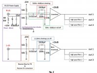
In the following schematic I use a transimpedance amplifier to transform the current to a voltage.
I “lifted” the output of the TIA to -10V by putting this voltage on the non-inverting input- which in turn sets the bias for the photo-diodes.
This reduces the headroom of the Opamp. One solution could be, to make the Opamp supply asymmetrical: +5 to -25V.
The following capacitor removes DC from the signal and can be part of the succeeding equilazation-network (can we call this still a RIAA-network?).
The channels are phase inverted to each other, so the right channel still needs an inverter stage.

Any comments so far?
Cheers, Boris
They are a bit pricey, but it's possible to purchase a DS-pickup without the equalizer, so DIYing the equalizer safes a fair amount of money.
Here I just want to gather some ideas on the construction of such an equalizer…
There is a pdf "Optical cartridge technical info" which can be downloaded on the DS website https://ds-audio-w.biz/products_info/
I've got all my information from there.
PSU requirements
The pickup consists of an IR-LED (one for both channel for the 2nd generation pickups and one each channel for the 3rd generation pickups) which needs to be powered
and two photo-diodes -one each channel- which need an negative bias voltage.
An LED (the “front light”) is in parallel to the IR-LED and seems to be an on-indicator without further purpose.
The IR-LED is powered from 8V via 68Ohm resistor. Diode Current is said to be 65mA for the DSE-1 and 80mA for the DS003.
There is a resistor in front of the IR-diode shown in the pdf, which probably serves to decouple the IR-LED from the indicator LED.
So the IR-LEDs forward voltage is likely to be approx. 2,9V.
The Photo-Diodes are reverse biased (photoconductive mode) and need a -10V bias voltage each channel.
Output voltage of the DS-E1 pickup is said to be 50mV. The schematic has a 16kOhm resistors to convert the diode output current to a voltage.
Diode-current therefore must be 50mV/16kOhm=3,125µA (5cms/sec at 1kHz???)
In the DS Audio pdf the RIAA equalization is shown as a passive network right behind the 16kOhm resistor.
I’m not shure if this is the optimal position. Also the I-V-conversion could benefit from an active solution.
In the following schematic I use a transimpedance amplifier to transform the current to a voltage.
I “lifted” the output of the TIA to -10V by putting this voltage on the non-inverting input- which in turn sets the bias for the photo-diodes.
This reduces the headroom of the Opamp. One solution could be, to make the Opamp supply asymmetrical: +5 to -25V.
The following capacitor removes DC from the signal and can be part of the succeeding equilazation-network (can we call this still a RIAA-network?).
The channels are phase inverted to each other, so the right channel still needs an inverter stage.
Any comments so far?
Cheers, Boris
Would this work?
I-U-conversion + step-up with an DAC-output or MC-transformer…
Note that the photo-diodes are in reverse direction, so no DC current is flowing through the transformer coils.
In the end I would prefer a solution with tubes.
Phase inversion of the right channel can be done by swapping the primary connection of the transformer.
Since this pick-ups have no coils, where the signals are induced (like MM/MC/MI-systems), the output signal depends only on the movement of the tip of the needle and not of the acceleration of the tip. This is similar to strain gauge pick-ups. So the usual RIAA network won’t work to equalize the output.
Also, these pickups can generate output from 0Hz upwards- so a high pass, to remove contend below the audibility threshold, is advisable.
Here is the plot of the passive filter from DS-Audio. They use a shelving high pass from 500 to 2120Hz combined with a 50Hz high pass.

In the green graph the network is fed by a linear ac-source, whereas in the red graph it is fed by a RIAA-curve-source (left upper & lower filter).
I modified the filter to use capacitor values where I have a lot from (filter on the left). This is of cause not tested!
I have the calculations for the shelving high pass from https://linkwitzlab.com/filters.htm#6
Could somebody here be so kind and create an ac-source with the correct functional equantion for velocity pickups?
Because this is beyond my skills")
Also, these pickups can generate output from 0Hz upwards- so a high pass, to remove contend below the audibility threshold, is advisable.
Here is the plot of the passive filter from DS-Audio. They use a shelving high pass from 500 to 2120Hz combined with a 50Hz high pass.
In the green graph the network is fed by a linear ac-source, whereas in the red graph it is fed by a RIAA-curve-source (left upper & lower filter).
I modified the filter to use capacitor values where I have a lot from (filter on the left). This is of cause not tested!
I have the calculations for the shelving high pass from https://linkwitzlab.com/filters.htm#6
Could somebody here be so kind and create an ac-source with the correct functional equantion for velocity pickups?
Because this is beyond my skills
The reference design using 16K I/V has -10V output.
Is that reasonable to reduce the I/V (3.3K) to get -2V output, and DC feed a single stage pentode (200-400X gain) with transformer output (10K:600).
No extra needs to be done for inverted output on transformer stage.
I've already built best pentode circuit using Lundahl 1660 to drive LCR 600 with very good result.
Actually I was wrong, -10V after 100k/33k is only -2.5V, perfect to dc couple to tube stage.The reference design using 16K I/V has -10V output.
Is that reasonable to reduce the I/V (3.3K) to get -2V output, and DC feed a single stage pentode (200-400X gain) with transformer output (10K:600).
No extra needs to be done for inverted output on transformer stage.
I've already built best pentode circuit using Lundahl 1660 to drive LCR 600 with very good result.