Amplifier

I am incredibly proud to announce I have made an amplifier with a schematics I have dreamt for a long while. I have only done very preliminary tests which are excellent. I have not yet written up the document, but, I am impatient to provide this information.

At present, the document contains the schematics only and will be updated, hopefully, soon.
Here is the link : Amplifier - Google Drive

Please, note : there are a lot of N. E. ( Not Equipped ) components. The reason to be on the schematics will be explained.

DIY project (Ekta 2D + Visaton La Belle combo)

Dear all,

Just wanted to share my DIY full range active speaker project which is a combination of the Ekta 2D design of Troels Gravesen (tweeter + mid) and the Visaton La Belle ( 2 x 8inch woofers) where the Hypex Fusion FA122 of the Ekta 2D is replaced by the 3 channel FA253 Fusion amp.
Cross-over between tweeter and mid is designed by Troels Gravesen (with first order, second order and 4th order LR options, all in the range between 2-2.5kHz), and LR2 cross-over between mid and bass at 300Hz (same as original Visaton La Belle):

Image 005.png

Image 006.png


Below the frequency response I measured with Umik-1 and REW software. Is a combination of far field measurement (same as Troels at +- 70cm distance from the speaker with microphone height between tweeter and mid) and a near field measurement of the woofers (corrected for baffle step loss), where in REW I selected the psycho-acoustic smoothing option:

Reponse psycho acoustic.png


In the end - after hours and hours listening and finetuning the hypex parameters - I am now very happy with the results! ;-)

Regards,
Wouter

Suitability Of Copper Clad Aluminum Enameled Wire for Magnepan T-1D Rewire

Any chance 10% Copper Clad Aluminum Enameled magnet wire would perform significantly better in long-term corrosion resistant durability & extended continuity lifespan ? .....As I've never seen any examples of long term solid copper enameled mag wire corrosion or pit opens, would 10% Copper Clad Aluminum magnet wire exhibit significantly Longer corrosion free Lifespan & Reduced pit--open continuity failures long-term performance ??


Jmj

Why bootstrap?

When I read this thread I wonder about one issue.

Hugh, and Rod are two persons here which are keen on using bootstrap for driving the output transistors.

I wonder what are the pros and cons?

Pros: More power with given design, more peak drive voltage, less parts, simplier power supply for the drive circuits.

Cons: Start-up thumps, poor bass performance(?), poor clipping characteristics(?)

Is the major reason to use bootstrap to save parts (=costs)?

Are there any sonic properties involved?

Nad 2700 recapping

Hi all,
I have a question about upgrading this amp.
Where can I get power Capacitors replacements for this old amp?

Power Capacitors 2 x 10000uf – 80v
Power Capacitors 2 x 10000uf – 120v

I found this upgrade kit (which I would probably get) containing
35 Nichicon audio capacitors KZ, FG, FW, KW but power Capacitors are not included.
Any directions or general thoughts about my plan (should or should not) would be highly appreciated.
BTW, The reason for the upgrade is that It makes some dearty sound from the speakers like bad contact sound from time to time. Do you think changing the Capacitors of a 30 years old amp might solve it?

My speakers are martin logan source.


Thanks

Dual DA6001 muted?

Working on a Dual DA6001 which appears to be just muted. I get very faint audio on speaker terminals at very high input signal voltage. Customer said amp never worked straight out of the brand new box, though the amp is several years old now. It powers up, has rail and regulated voltage. All opamp outputs have audio signal on them, and there is audio going to Pin #8 of the driver board, which is using IR2113 and a new one: HCF4093.

I see a square wave on the HCF4093 at several pins including pin 8.

On the IR2113 I have the following voltages:

1. -68.9
2. -68.9
3. -57
4. 0
5. -0.027
6. 0.330
7. -0.021
8. 0
9. -57.1
10. -57.1
11. -68.2
12. -68.9
13. -68.9
14. 0

I'm not seeing any drive nor signal on output FET gates.

Polar maps for W4-1320SIF, FF85WK & FF125K

Or "Why should the fullrange gang not also post those pretty colourful graphs" 😉

I was measuring the response of drivers for a multi-way project and though I'd give my FR drivers a spin, quite literally!

These are all drivers I've had for many years:
  1. Tang Band W4-1320SIF, mounted in a 9 liters DCR
  2. Fostex FF85WK, mounted in a 3.25 liters reflex
  3. Fostex FF125WK, mounted in a 8 liters reflex
The first two are relevant as they are current production units, whereas the FF125K was measured for kicks mostly. All vents were stuffed with balled-up tissues.

I measured 0deg to 90deg in 5deg steps, which is mirrored on the polar maps. The SPL should reflect sensitivity accurately enough; I set the amplifier for 2.8V and placed the mic at 50cm, then reduced REW's output by 6dB.

First off, all three drivers on-axis, for comparison's sake:

w4_85_125.png

W4-1320SIF 0-45deg response and polar map:

w41320sif_0-45.png

w41320sif_dir_1k.png

FF85WK 0-45deg response and polar map:

ff85wk_0-45.png

ff85wk_dir_1k.png

FF125K 0-45deg response and polar map:

ff125k_0-45.png

ff125k_dir_1k.png
  • Like
Reactions: grindstone

Cast in stone speaker

The Glencairn Museum in Bryn Athen, Pa., has an unusual built-in-a-wall bass horn with a mid/treble array that must have produced a fair amount of volume in its day. Located in the "Cloisters" area, it is easily missed on the usual tour unless you check it out on your own. The museum was the home of Raymond and Mildred Pitcairn from 1939 (in construction 1929-1939) until 1979. What a blast it would be to fire it up again!

Attachments

  • IMG_0310.jpg
    IMG_0310.jpg
    729.4 KB · Views: 137

Aragon D2A upgrade path?

I have an ARragon D2A Dac, which has been upgraded to D2A2 with factory-supplied upgrade kit. Looking "under the hood" I see it has 2 Burr Brown PCM58 DAC chips and a Yamaha YM3623B. There are 14 other chips too, but I have no clue what they all do. I will list them if needed (All start with P and end with G, eg P8930G)
Is there a plug-in replacement for the PCM58 which would actually bring about a real improvement in this unit, or would I be fiddling about with swings and roundabouts if I tried to change them?

Woden Baby Labs Bloodhound build

Oh no!
My 15+ years old refurbished Klipsch Promedia GMX A-2.1 speakers finally died!

PXL_20211005_121109116_result.jpg


What a great opportunity to build my own set of desktop speakers. In fact, the sub died more than a year ago and I've been listening to those little cans ever since. Life always finds a way to gobble up all your free time.
In the past I built 2 pairs of ZaphAudio Hi-Vi B3S for my daughters which are great but I wanted to try something different. It took a while to figure out what to build. I have very limited space on my working desk so form factor was a huge element to consider. With the help of many forum members I decided to build the
Woden Design Baby Labs Bloodhound
https://wodendesign.com/downloads/Woden-BabyLabs-241018.pdf.

Got my cones and terminals ready (thanks planet10)!
PXL_20211009_150944576_result.jpg


To make things more complicated, I decided to go with hardwood, Curly Ambrosia Maple. I was careful not to pick planks with holes in them as it often happens for this type of wood.
PXL_20210925_203731318_result.jpg


PXL_20210925_203759514_result.jpg


PXL_20210925_203845760_result.jpg


I'll post my progress here and any question I might have! Hope this helps someone else in any way, the other build threads helped my a lot in the past.

Distortion & Feedback in Tube Amplifier using LTSpice

I just recently tried to use LTspice to model the KT88 push pull amp and have a few questions on the output wave form in general. My amp will be based on 3 stages. Input stage (6SL7) will direct couple to driver stage (6SN7) then capacitor couple to KT88 to drive my 5K output transformer. So far the simulation indicate that output waveform taken from output tranny 8 ohm load showed a very clean sine wave with distortion less than 1% from 20 to 20 Khz with max Power output at about 50W RMS with global feedback from 8/16 ohm to input stage. I also checked both output of the input and driver stages wave form. They both showed very clean sine wave output if output power is less than 35W. However, both input and driver output stages sine wave start to distort if power output is driven above 35W and get worst with increasing in power output. However, as mentioned earlier my output sine wave from output transformer still showed a clean output sine wave and total distortion less than 1%.

Is this normal what you would see or expected from input and driver stages when using Feedback? Or I need to fix the input and driver stages? Thanks in advance for the input.

Sansui AU-X11 oscillation

I repaired a channel in this amp using T03P outputs ( 2SA2223a & 2SC6145A) and replaced the blown drivers with Toshiba TTA004B & TTC004B.
Its up and running, but I'm getting oscillations looking at a square wave at 10kHz .
I tried adding 47pf caps to the drivers with no luck... Should I be adding some caps to the outputs as well??

Attachments

  • IMG_20220409_125144431.jpg
    IMG_20220409_125144431.jpg
    329.1 KB · Views: 190
  • HykjR2R.jpg
    HykjR2R.jpg
    618.2 KB · Views: 242

SX-1250 channel outputs blown... what is this failure mode? Things to look for.

Hi Everyone,
I hope you all are well and sociable. I am working on a Pioneer SX-1250 with a blown channel, and I am in the later stages of repair. I'd be about to test the amp right now, but I wanted to ask the group two questions.

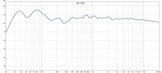
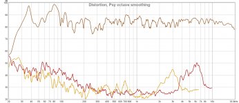
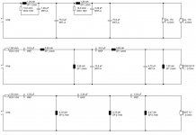
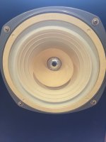
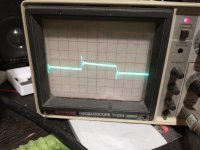
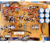
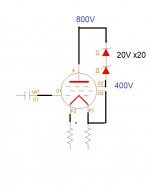
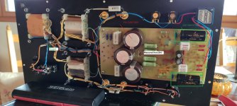
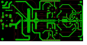
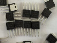
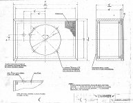
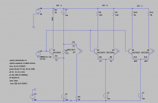
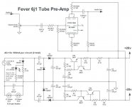
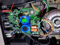
The analysis showed a blown 12A main fuse, and one channel dead - I disconnected the power supply to the suspected side's driver board, installed a new fuse, and the amp powered up and produced a great looking/sounding signal on the good channel. Next, I pulled the driver board and tested the outputs - shorted TO-3's. I then pulled the power supply/protection circuit boards to look for issues. The outputs have been replaced with MJ's and ECG 68's - I am matched for Vbe within .01V and Hfe within 1 point, as this Pioneer does not have NFB. The driver board had a few issues, and I have attached a schematic with colored pen circling the burnt or damaged parts.

Questions:
1 - The drivers (low voltage Peak meter test, in-circuit) and emitter resistors test fine, and this is the first thing I check when executing a blown output device repair. Is there anything else I should check before testing?
2 - Is it possible to describe the failure mode, or or to see what kind of scenario that this amp ran into at the time of failure? Damaged components are circled (notated) in blue/red pen, and the green markings are there to remind me to check pins 1 + 7 and where they lead. With R24 and R25 failing (one open and the other discolored and +25% tolerance), I am surprised that Q7 (2SC1904a) and Q8 (2SA899A) are not testing bad. Should I trust them? Q11 (2SC869) is the only transistor that tests bad (short, tested out of circuit) on this board, and has been replaced with a 2N5551. This makes understanding how R41 got damaged easier, but not R27 as Q10 tests good. Is Q11 a protection circuit xs?

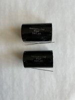
Bonus question: The tape that holds the "MicroTemp" 109C temp fuse to the heatsink has let go, what can I use to replace it?

Thanks.

Attachments

FS: Scanspeak D3004/6020s, SB Acoustics SB29RDNCs, and Eminence SD28 Tweeters

1. Scanspeak D3004/6020-00 Tweeters (Pair)
2. SB Acoustics SB29RDNC-C000-4 Tweeters (Pair)
3. Eminence SD28 flangeless textile tweeters (Pair)

Prices:

1. $160 shipped to Continental US
2. SOLD
3. $30 shipped to Continental US

Condition:

1. Used in good working condition.
2. Used in good working condition.
3. NIB

Photos:


DEQ 2496 Remote Controll (under construction by myself)

Hello
I noticed a lot of topics on the DEQ2496.

Well I'm programming a PC program to control your DEQ2496.

It is stil under construction but it seems to be working fine.
The bits and pieces that I put into it, that is.

Full coverage of the DEQ, 95% of the I/O settings and the Bypass modules. And one real fun option a screen dump of the DEQ wich is copied to the clipboard.


It's suppost to be working Bidirectional, changes on the DEQ are noticed by the program and vice versa.
With one button you can copy the DEQ values to the program.

The latest version should run under win8 64bit
http://www.seoman.nl/deq2496/DEQremote.html


I would like some feedback on it's fuctionality.

Greetings,
Simon aka Seoman

An externally hosted image should be here but it was not working when we last tested it.

An externally hosted image should be here but it was not working when we last tested it.

An externally hosted image should be here but it was not working when we last tested it.

An externally hosted image should be here but it was not working when we last tested it.

4 x 3" short line array loudspeaker

Sold.............


4 x Fountek fe 87

Sealed box
Professionally soldered
Acoustuf
Originally owned / made by mpm (diy member here).
A good way to try without costing much !!!!!!!!


$100 + $30 shipping (I'll mail difference if under)
I Would love a money order.

Thanks for looking !!!!!!

Attachments

  • 20210603_141258.jpg
    20210603_141258.jpg
    392.7 KB · Views: 761
  • 20210602_154608.jpg
    20210602_154608.jpg
    449.8 KB · Views: 706

Philips CD-951: Tent Labs XO3 and SPDIF reclock plus I2S out

Dear All DIYAudio members:

Anyone have experience on modification on Philips CD950/951 with Tent's XO3, or similar machine, any help and advise would be welcome!

I have a Tent's XO3 Module with reclock option, as the manual of XO3 mentioned, the SPDIF data out should be taken out from Pin 32 of SAA7310GP (http://www.tentlabs.com/Components/XO/assets/XO23mounting.pdf), indicated as HFI of Data Slicer, as other information come across about SAA7310GP, SAA7310GP have no SPDIF out, the SPDIF should be handle by PCF2705, converting I2S from SAA7310 into SPDIF format, and output at Pin 13 of PCF2705.

So where should I extract the SPDIF for re-clcok in of XO3?

and I want to take I2S data out from the CD-951, instead of wiring at Pin 2,3,4 of SAA7310GP, can I extract the I2S from Pin 1,2,3 of PCF2705? Can I do this??

I hope Guido can see this post, I have a hard time to get advise from him.

Thank you for reading.

Parafeed choke and transformer values.

I'll keep this simple.
This is a side line topic from my gu81 se amp build.
After a lot of reading on output transformers and also looking up parafeed combinations I'm left rather confused. But this is what I can deduce...

-Plate load choke needs to be like a normal opt transformer so say approx 50-100h. What determines this value?

- the opt transformer remains the same impedance as non parafeed combinations. I'm no engineer and I'm assuming the plate sees the capacitor as a short circuit at audio frequencies, hence the opt remains the same

-coupling capacitor should fall between 3uf-8uf

Now I'm not looking for perfection yet.... Just a working combination/prototype

Tim

IKEA BROR for system stand and record storage

Good evening or good day, depending where you are.

I just moved to a new condo and I was looking for a sound system stand and a way to store some of my records. Most units are multimedia units that have small drawers and not deep enough for turntables. There are some commercial offerings but they are very expensive. My next plan was to build my own using "russian plywood" or american walnut.
I did have to go to Ikea to pickup some items, but I usually find their furniture to be on the cheap side (won't last 20 years unless you just look at it). To my surprise, I found a solid work bench with interesting dimensions. Took the measures and looked at it from many angles... and decided to get 2 of them and cut about 10" from the legs. Here's the result.
Still a bit messy... but you get the idea. I love it. Ikea BROR, 2 units at $189 CAD each.... so about $400 for the set. The top is plywood, the legs and shelfs are metal.

67088279532__22ECB7E0-91E2-47EF-ABEC-4E7C31CC0736 (1).jpg


Let me know what you think.

Peter
  • Like
Reactions: sachu888

GB for ES9038PRODAC-Core

With our good experiences with our new ES9028PRO/OEM board in some projects, we want to build a universal platform based on the ES9038PRO. The new 9038PRO-Core, the IV stage and the digital inputs are on individual boards. This allows each unit to be used independently.
The AKOUO Controller Board is recommended for initialisation and controlling.
Here are some features of the new board or the planned features for the additional modules

ES9038PRO Core:

all DAC outputs on two header can be used for Stereo/4 Channel/8 Channel output
separated power supplies
AVCC-L/R with two LT3045
multiple LP5907 for 1,2V DSP and 3,3V Logic and CLK
5x7mm CLK and COAX for external CLK
Input multiplexer for I2S and Spdif (Data1-5) blocks digital signals on unused inputs.
extra Header for Data IN6-8
I2C input with enable to isolate the I2C if used on other boards
full SMD assembled and tested

I/V-Stage:
8 channel balanced I/V converter with OPA1632
four channels connected parallel in stereo mode. Rout is about 100 Ohms T and therefore you do not need an additional output driver.
Dual tracking regulator with TPS7A4700/3300
Enable controlled from the DAC-Core, to prevent unwanted DC on the DAC-chip during power up

Digital input board:
AES-EBU and/or Spdif
AES EBU pass through
Amanero
2 x Toslink
general I2S input for Raspberry, MINI-Shark...
LVDS I2S Port …..


The 9038PRO Core is ready for production. We want to share this project with you and we look out for interested people in this project to get a better price for the production.
The calculated selling price for the first series of the PRODAC-Core is about 420€ excl. VAT.
If we have 20 orders more the price will be reduced to 360 € excl. VAT

The IV stage and the digital input board are in the final design phase and I am also looking forward to some new suggestions and discussion on these designs.

Best regards

Attachments

  • 9028PROTO_Sample.jpg
    9028PROTO_Sample.jpg
    87.1 KB · Views: 1,347
  • PRODAC-Core9038.pdf
    PRODAC-Core9038.pdf
    147 KB · Views: 276
  • PRODAC-Core9038.jpeg
    PRODAC-Core9038.jpeg
    116.2 KB · Views: 1,327

Meter Calibration - OEM or Metrology Lab

I'm working on a DIY project that requires accurate AC and mV AC measurements. In 2016, I sent my HP 3400A and another HP400 series meter for official calibration to a Metrology lab in the North East. Got the full reports, cal stickers and Void if removed stickers over screws. Wonderful. My handheld DMM and 4 1/2 digit bench top meters do not match each other and do not closely match the HP meters. Yes, all have been on for hours, etc.

So I'm debating where to send the digital meters. The Metrology lab said send them and they will most likely be able to calibrate them. However, I hate to waste shipping dollars if they can't. My meters are BK Precision 2831E and Extech MP530 (a Fluke 87 knockoff). BK wants quite a bit of money to cal and then return. I'm not getting a NIST cal, just a regular cal with documentation. Still pricey. I called Extech, which is now part of FLIR and they are not sure they handle the old product lines. I asked them to provide the calibration documentation so I can forward it to the Metrology lab. I am waiting for tier 2 support to respond to that request. I don't have good hopes on them releasing the info.

Any opinions about OEM vs Metrology lab?

Before anyone craps on the Extech (fluke knockoff), I refuse to buy Fluke products. In my industry, they have totally ruined the test equipment products by buying up other vendors, end of life their products, and then force the new over-priced & unreliable crap down our throats. It was so bad, a $20K analyzer kept loosing cal settings and was returned 3 times in a 12 month period. They refused to send a new unit in exchange for something that was in for service more than in my hands. When we spend $100K on test equipment, I now support the other vendors as much as possible. And their products are as good or better than Fluke. OK, off my soap box.

dont know what to do

hey need help.....
i have a 2 beyma 122nd, 1 has a hole in it the size of 50 cent piece, the problem the model is discontinued, speaker is about 22yrs old, but the quality of sound that comes out is phenomenal, beyma dont have no recone kits, i patched it but if i go pass 20, in volume it clips the amp.. thinking the patch made it unbalanced

so do any 1 know what i can do without replacing to a whole different speaker
, looking up to the skies

The "Stupendous" 6P1P 4PP amplifier!

Updated to show latest schematic. Boards are available if anyone else wants the best sounding 10 Watt class A triode output tube amp you can build for under 500$USD. When I built this, 6P1P were available for $1 each.

1676943175122.png


So the design uses a PPPP design meaning 8 6P1P per channel.
According to Push Pull Calculator the numbers look interesting.

Since I have the parts laying around I thought I might build the following "stupendous" design. Stupendous in the sense that it's about 10% efficient.

In case it isn't clear, the 100k grid resistor is shared. In reality, if this sounds anything like it sims to spec, It's a contender to replace more expensive tubes such as 300b, providing electric power is cheap where you live. I'm fortunate enough to have my electricity included in my rent(!).

What do you all think of this?

EDIT: I took a look inside of it after it's been on the shelf hooked up for a couple of years - better than expected... No bulding caps in the SMPS for the heaters 🙂
Here's a shot of inside.
2023-02-20 20-46-57.JPG

Upgraded AirPort Express power supply LM1117

Hi everyone

I searched a long time for a good sound on my system

System:
Accuphase e205 amplifier with Van Damme Lcofc hifi Cables 2,5 And Dynaudio floorstand speakers Excite X32

I had a Bluesound Node n100 streamer And streamer Spotify lossy files And wanted to play lossless so decided to stream with Apple music (now to try for free for 4 months
Than i searched for a streamer for Apple Music And came out at the Airport Express A1392 (last generation) with AKM4430 Dac chip in it
After reading a lot about to change the standard Power supply Build in into a seperate supply external i Build after searching And trying a lot this unit (see pictures)
As they said that it will make a hugh difference and peoples talked over the internet about a audiophile high-end dac i was sceptical about it

So I wanted to use the Apple IPad charger as L.P.S. with very low ripple and noise, regulated on the entrance (220) as it work well as a low cost power supply 5V

In the AirPort express I took out the original power supply and build a print with the LM1117 voltage regulator to regulate 3,3v needed for the AE to work
2 ceramic condensators of 100nF at in and out for distortion filtering a cap (normal Panasonic) of 10uF at the in and I had in my collection from an old tv a cap from Philips 100uF (audio appl) with low ESR for the output

So I was very curious and do the test ..

Well, i must say that this is a releave for me … the sound is superb with everything i ever wanted in it!!

Depth, detail, warm and clear sounding together what I hadn’t got in the paste!

Everything can change and also can be better but for know I must say that I am a happy guy 😁😁😁

Anyone with remarks? Anyone who did also changements to an Airport Express?
Please share

Greetings Jayzee 2912

Attachments

  • 14B4C041-70D7-49B6-81B8-7693AC2816B1.jpeg
    14B4C041-70D7-49B6-81B8-7693AC2816B1.jpeg
    368.1 KB · Views: 456
  • A8EFE32B-1C21-4E45-AF52-71A403B61E03.jpeg
    A8EFE32B-1C21-4E45-AF52-71A403B61E03.jpeg
    346.7 KB · Views: 362

Replacement CD platter tray for Shanling CD 3.2

Somehow, the CD platter tray on my Shanling CD 3.2 has pressed down such that the CD will not properly spin. It appears that there was some type of retainer in the center hole of the tray and that it has now gone missing. Maybe glue that decayed over time. I'm not sure.

I am searching for a replacement and for the height adjustment instructions once I have the replacement in hand.

Is anyone able to help me?

Thank you.

180V B+ EL84 amplifier, is that plausible?

Hi

I am trying to figure out what the B+ voltage is of my headphone tube amplifier, I am getting 180V seems low to me I've read that El84 tubes usually run with 300V plate voltage?

I measured at the jumper to get over the gnd line to bias the other side of the first input tube.

I'll attach some schematics and a picture and mark where I connected my multimeter.

Here is also an Imgur link with the images, it's telling me that the schematic file is too big to upload.

Login to view embedded media

Attachments

  • IMG_20220402_182548 - Copy.jpg
    IMG_20220402_182548 - Copy.jpg
    267.2 KB · Views: 107
  • unknown.png
    unknown.png
    662.1 KB · Views: 98

Lovoltech LU1014D

Hi Pals,
I been entrusted with distributing these lovely power Jfets by our Papa.
I will be charging a 1.50$ Per SALE( per person)covering for gas expenses and packaging etc.
Yes you read it right , they are free from Papa.
So total number per person limited to 4.
They are not matched and no matching needed ,in Papa's designs.
Don't forget to add shipping method in email and incurring pay pal and shipping fee to the total expenses!!!
For US guys flat 5$ , will cover everything (my charges of 1.50 plus USPS first class package)friends and family only to make life easy for me .
I will ship out every 10-14 days. So depending on when you pay also will decide when you get them.

Include your Address and PayPal accounts to reduce traffic on mail servers!!

Note:This is a not for profit venture so no refunds or returns whatsoever 😉
Friends from Europe please contact Carsten.witt , he will distribute 100, (25 people with 4 each)
Canadians Please contact Algar_emi, distributing 56.

Attention: Fellow Americans Please include your shipping address and mention 'FET 'in your friends and family transfers. Please don't get upset if you see a refund. Happened because I can't find out your details. Please send back with details.
Paypal friends and family don't provide address automatically
.
All non- friend and family transfers from US pals will get refunded too , from now on.

Attachments

  • image.jpeg
    image.jpeg
    776.8 KB · Views: 1,425

Bl plotted against displacement

I'm designing a sub driver and have identified a Bl value I'm aiming for of around 30Tm.
Through simulation of the magnet and coil I have this plot of Bl against displacement.

1649886998596.png


The displacement values at the bottom are a bit misleading. But basically 30mm is mid point of the coil length. So i get the desired 30Bl value there. But I'm wondering what effect the drop off as we move away from the centre of the coil has on motor strength? I know that a flatter Bl(x) curve is preferable. But what is the real world effect of having a drop off like we see here?

Thanks

First Order Crossover Design in VirtuixCAD. Thoughts?

Hey diyAudio Friends.

I am designing and building my first set of desktop speakers. Casting them from concrete! See below.
Here are some specifications:

Internal Volume 3.1 L
Woofer: Dayton Audio TCP-115 8Ohm
Tweeter: Dayton Audio PTMini-6 Planar Tweeter 6 Ohm

I am currently designing the crossover. I am using VituixCAD to do the modelling, but I am a total newbie.
Could anyone give some input. I am especially confused about the power supply settings.


Any input is appreciated!

Thank

Sam

1stOrder.png

DesktopSpeakersV2Render.png

Firmware for Denon dvd 2930 - Help me please!

Hello everyone, after a long time I return to the forum.
I am struggling with a Denon dvd 2930 that unfortunately has no audio, neither Cd nor Dvd at the analog outputs. The Cd works in HDMI but not the Dvd. The video is great, very stable, does not lose a frame. Excluding optical pickup problems, in Test Mode I noticed that in the firmware check I get BE 8283-B MAKE DAY 802 DSP 00.00.
In the service manual indicates that when the DSP is 00.00 means that first of all you have to insert the firmware in the FLASH ROM, if there are no other hardware problems.
I'm searching everywhere on the net but the links where to download the firmware do not make download anymore, the same in the official support page of Denon.
I was asking if you have the firmware for the 2930 (European version) mentioned above.
I really need your help.

Switching amplifiers directly from power strip

My amp, Usher R1.5, consumes around 50 watts when plugged even when it is off as a circuit is active to keep the amp warmed up, to save on electricity I disconnect the power cord. To make it convenient, I installed a power strip with an on/off switch and leave the power amp in the On position and just power on/off using the power strip. Would there be any ill effects using the power strip as main switch for the power amp?

Tannoy Dual Concentric 12" - Small Cabinet

Hello,

I was wondering what I loose/gain by building these smaller cabinets ( see attached photo ) compared to bigger cabinets based on original Tannoy plans.

Ref ( comparison ) : http://www.44bx.com/tannoy/images/Lancaster3.gif

TNT ( comparison ) : [DIY project] DIY Tannoy 12" Dual Concentric Horn

INFO:
This IIILZ cabinet will be my speaker cabinet in my second hifi system.
It is needed to be a smaller cabinet, posting because of thoughts of cabinets for the future... and info from other builders that understand cabinets better than myself...

- Is it the bass frequency I will loose compared to Lancaster? This I can live with , but if there are other things I loose I would greatly appreciate an informative answer.

PS: I have already started building the IIILZ cabinets 🙂 - will post pictures when finished !

Attachments

  • IIILZ_2.jpg
    IIILZ_2.jpg
    162.9 KB · Views: 1,977

Alternative IPS

Hi,

I was looking for IPS, which would nicely suite push-pull VAS, and came up with an idea to rotate half of differential input (IPS-A). First simulations seems interesting but I couldn't find any info. There is no point in reinventing the wheel, so any indication/name of such IPS/comments would be very helpful. Thanks.

Stanislaw


Schematics and FFTs attached (initial idea validation):
  • 2nd harmonic is higher but it doesn't require additional circuitry to move signal to opposite rail (IPS-A vs. IPS-C),
  • part of it is probably generated by Beta differences (not optimal transistors),

Attachments

  • Schematics_test.png
    Schematics_test.png
    14.9 KB · Views: 128
  • IPS-C.png
    IPS-C.png
    20.8 KB · Views: 130
  • IPS-B.png
    IPS-B.png
    20.7 KB · Views: 98
  • IPS-A.png
    IPS-A.png
    20.5 KB · Views: 132
  • IPS_test.asc
    IPS_test.asc
    3.9 KB · Views: 49

Differential sensing RCA

Some amps have input like this. While the input is RCA (not balanced), the receiver is configured to sense differential between + and - (like balance input receiver).

Both the + and - are passed via capacitor (E001-E002-E003-E004). The - (shield) is not connected directly to ground, but by capacitors (C021-C022)

What is the merit of doing this? Better sound? Breaking ground loop?

Why not just connect the shield of the RCA directly to ground?

Attachments

  • differentialiinput.jpg
    differentialiinput.jpg
    90.2 KB · Views: 686

Cyrus Two voltage regulator fried.

I got Cyrus Two (issue 06) with problems. The previous owner said that only one channel works. I tested with headphones and both channels work however one is significantly lower in volume. And there is some distortion.
When I look at the PCB it is clear that some parts have been overheating. First test of Power Supply goes fine until voltage regulators VR1 and VR2. Both put out (+-)17,8V. However these VRs are overheating fast.
I remember reading that these VRs are not very good and could be replaced with better contemporary ones.
The problem is further down the line somewhere. I wonder if there is a obvious place to check first before I start to to follow the signal path step by step?

Musical Fidelity E11 needing second repair

Hi,

I'm new to amplifier repair and I need some advice here. I received some times ago a Musical Fidelity E11 to repair from a friend of mine which did not power up. The fuses where broken so, I quickly tested parts and found that all the right channel power transistor were shorted. So, I replaced every one of these 4 TIP35C as well as the TIP31 which was on the heatsink. I also checked what seem as the previous stage of power and noticed for every ZTX753 and ZTX653, once desoldered and tested on my multimeter gave a way too small Hfe value. So I replaced them as well. As every component around seemed ok, I powered the amplifier and everything working fine, gave it back to my friend.

He uses his amplifier for some month without any problem but now, he gave it back to me saying there was a faulty channel. What is strange and why I post here is that it's again the right channel which is broken. But, this time, there is no short on the power transistor but I measure about 46/48V DC on the right speaker connector. So, before I desolder anything to test (as none of the transistor seems shorted or broken with a simple diode mode test) I'd like to know if this new problem may come from the previous one or my repair which may have not been properly done. I noticed a trim pot but did not touch it. I search and found this post which suggest it's a current biais but I cannot find any information on how to adjust it correctly (if a transisor replacement need any reajustment)...

Anyway, could any of you suggest a better way to find what is the problem? Maybe someone has the service manual or the schematic for it which would eased my research?

Thanks for your help and advices,
Simon

Need help troubleshooting tube amp

Hi. I have a Mesa Nomad 55 amp that's giving me trouble, and I was wondering if anyone here would be willing to help me track down the problem.

I recorded a video that shows what's happening, but I'll try to explain here, as I don't know how to share the video.

All 3 channels work. Master volumes and gain controls work. Lights come on, and the voicing switch on each channel works.

However, none of the tone controls works. On channel 1, if I rotate the treble control down to around 8:00, the amp suddenly gets loud. One other control does a similar thing at around 3:00. I think it's the mid on channel 2.

Anyway, I'd like to get these tone controls working. I'm thinking that since all 3 channels are affected, it's something in the circuit where everything's combined, and maybe the whole tone stack is open or grounded, but I can't find the problem. The board shows no signs of overheating, nor do any components, and there is no evidence of abuse. While I see what look like many "cold" solder joints from the factory, I can't find any cracked or loose connections.

Wondering if anyone can give me some clues on where to test.

ebay 6J1 valve pre-amp - circuit diagram/gain

There is a plethora of 6J1 valve pre-amps on ebay from china/hong kong.

Photo of a typical example is below.

I would like somebody to confirm the circuit diagram is the correct one. I've buzzed 3 resistors (not the ones in the voltage multiplier) and they match so I am reasonably sure it is correct.

But I would like to know how to convert the circuit to unity gain (i.e. to behave as a buffer). The potentiometer is to be removed and resistors to control the gain changed - but so that there is not clipping and frequency response is unchanged - hopefully that is possible.

My guess gain is set by (R13 / R14) = 470 k / 200 or by comparing to another circuit I have, is it (R16 / R150 = 100 k / 4.7 k ?

Attachments

  • 6j1 x2 amp.jpg
    6j1 x2 amp.jpg
    115.8 KB · Views: 2,693
  • 6j1 x2 amp1 - circuit.jpg
    6j1 x2 amp1 - circuit.jpg
    97.2 KB · Views: 4,433

Custom Linux-based portable DAP

Hi All,

I would really like a dedicated DAP to replace my phone, however I use a Subsonic-API music streamer (Navidrome) primarily. I have used the various iOS apps, but none really work well particularly regarding sync and shuffle play.

I have built my own desktop player using the Subsonic API in Swift, and have had the crazy idea of building a DAP based on this software running Linux. I could use something like the Pimoroni Pirate Audio board, but would rather have everything in a single board with a 4-5" display and larger battery.

I have made some initial research, and have asked an electronic engineer to create a prototype PCB based on the ESS ES9218 DAC/Amp and an ARM Cortex processor. An SD card slot or WiFi could be used to load the OS/music, and a 3.5" output would be included. If a WiFi/BT chip is included, there is no reason BT streaming to/from the device could not be included also, or USB audio out etc... The sky is the limit when a general-purpose OS is running and the hardware is open.

Has anyone done anything like this or would be interested in such a device? Any thoughts on the DAC/Amp combo? The ESS chip is relatively expensive, but does have a Linux driver as released by LG. There are obviously other separate chip DAC and amps that could be used.

https://beebom.com/developer-built-diy-winamp-mp3-player/

https://shop.pimoroni.com/products/pirate-audio-headphone-amp

https://opensource.lge.com/osSch/list?types=NAME&search=lgmv300s

https://evanhailey.com/2021/09/20/spot-box/

50 degrees C. temp at idle

I read somewhere in this forum that to bias a Class A amp, Nelson Pass recommended that the heatsinks needs to operate at 50 degrees C. Wouldn't the heatsink temp be dependent on the size of the heat sink? meaning a larger heatsink would require more idle current to heat the heatsinks to 50 degrees C, so if two identical 50 watt class A amplifiers circuits are made with one having a larger heat sink, the one with the smaller heatsink would have less Class A watts vs the one with a larger heatsinks, is this correct?

Seeking a Triode Electronics chassis for the diytube ST35

I built one of Shannon Parks' diytube ST35s on a Hammond chassis 20 years ago. It still sounds great, and even better with the new JJ tubes I scored right before everything shut down. But I've always regretted not buying one of the nice Triode chassis when they were readily available. So if you've been sitting on one, let me know. I'd also be interested in a complete unassembled kit should anyone have one of those.
Larry Fisher
Port Townsend Washington

WTB minimus 21.

hi i am Rob. i hail from the UK. if there is anyone on here who knows someone selling a pair of Minimus 21 speakers. they must be the ones with the two speakers and aluminium
floating tweeter. someone on here had bought a pair and someone else said they were only made for the Aussie market but i bought a pair back in the 80s from Tandy store in Hull in the UK. please get in touch on my email.
thanks everyone.

Augspurger GA15X-8 Opinions?

Just when I was about convinced I was going to drain my bank account and buy a pair of TAD 1601A, I discovered that Augspurger is now replacing the 15" TAD TL-160x woofers with the Augspurger GA15X-8 that they had designed to provide the same performance as the Pioneer.

Does anyone have any first hand experience with the new Augspurger 15 inchers? Do they really perform identically to the TL-1601a for example? They are ~$200 less per woof than new 1601A TADs.

White resistor vs green resistor?

Which resistor is better for a home audio application? I’m sure they sound the same, but one of them is probably constructed better. The green one is a few cents more but that could simply be because they’re less common. Tolerance is good enough for either.

I have had the white ceramic ones crack off pieces from the corners, and the leads are short. Green ones have longer leads and no ceramic to crack. But does the ceramic dissipate heat better? I can’t tell what the green coating is. Little worried it is like a paper wrapping that will start flaking apart in 10 years.

212E8281-B8B8-4ABC-B0A3-930E7B13F1D6.jpeg
C2E70F83-7995-4555-A76D-210B821A14BA.jpeg

The DIYRM-A, Two way Dayton RS150P and RS28 Tweeter-60 Page Design Guide

So, what started out as a quick little writeup about crossovers...turned into a bit more...about 60 pages more.

The DIYRM-A is a Do-It-Yourself Reference Monitor....much along the lines of an LS3/5a. Can be used a bit more broadly and works better with modern music.

The writeup can be found at:

goo.gl/XboqRW


The document covers:

Introduction
Design Goals
Driver Selection
Enclosure Design and Construction
Design Measurements
Crossover Design
Listening Notes
Crossover Power Handling Testing
Conclusion

They are excellent for a variety of applications from near-field monitoring, two channel stereo where space is a concern and surround sound applications, again where space prevents the use of larger designs.

I hope you enjoy.

Scott "SpeakerScott" Hinson
Projects by fanatics, for fanatics
Get answers and advice for everyone wanting to learn the art of audio.
Join the Community
507,685
Members
7,884,221
Messages

Filter

Forum Statistics

Threads
406,035
Messages
7,884,221
Members
507,685
Latest member
EvenLouder