You know when a project goes too far...
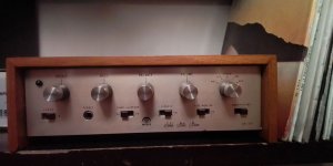
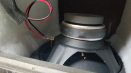
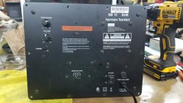
I've been on the hunt for an old amplifier for a while. It started out life just needing a new amp, but I got drawn to old kit: dancing VU meters, big knobs and glowing fronts. An opportunity came up to by a pair of old Rotel RA-314's - both broken. There was just something about them: wooden cased, glowing VU meters, aluminium fronts. 1979 vintage I believe.
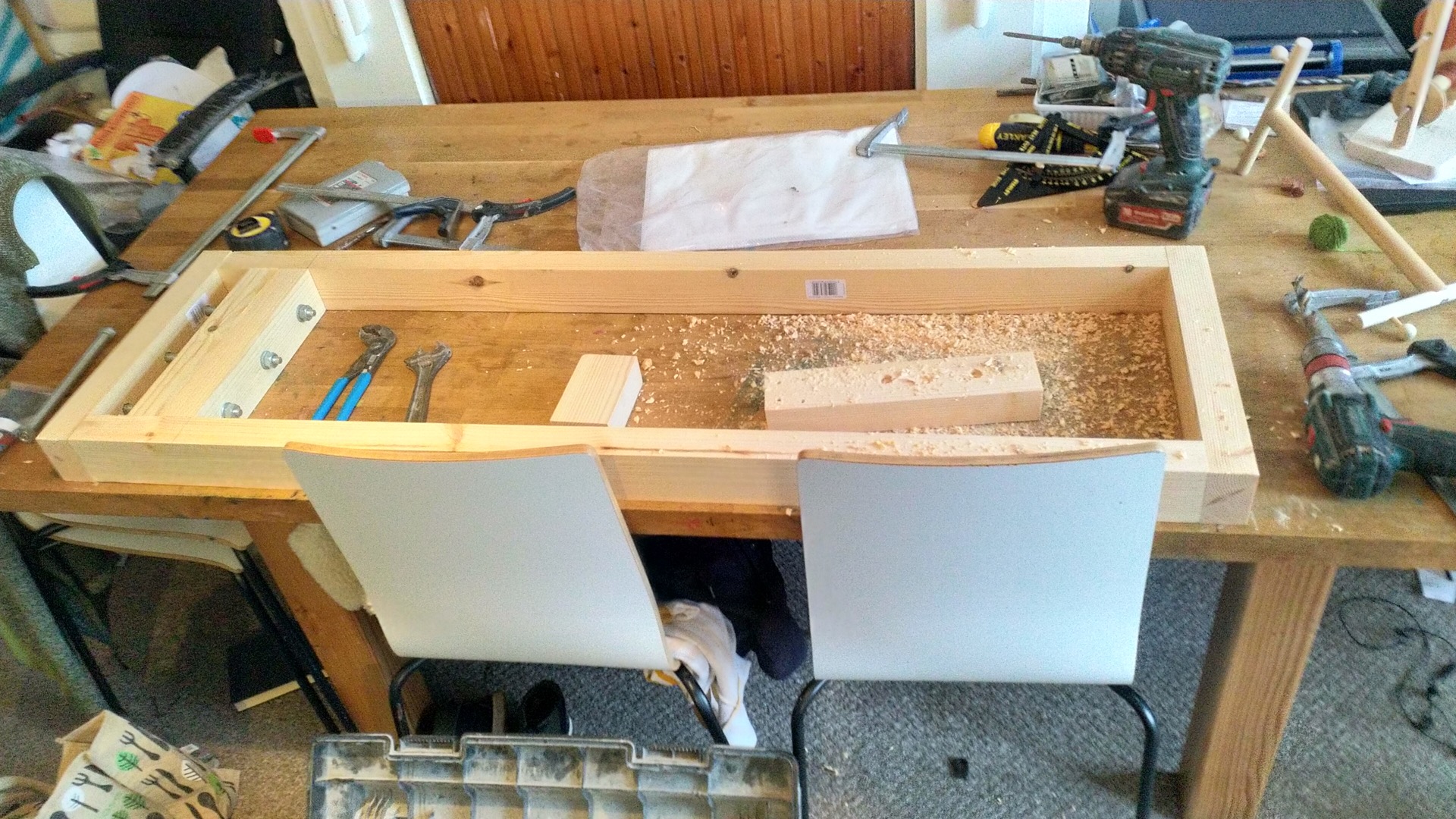
Of the pair, one wasn't too far gone and came back to life quite easily: just needed a new volume pot and output fuses. Suprisingly, everything else checked out. The capacitors are all original, none of them showing signs of obvious fatigue or failure. The casing needed some TLC - some of the wooden joints were splitting so a delicate application of glue and polish. This has been running in the living room over the last month or so just 'doing its thang' quite merrily.
The second one was in a far worse state. The obvious spots were a badly bent chassis (how?) and some dry joints from where someone else had attempted to re-cap the thing. The chassis was easily dealt with by a lot of hammering and reshaping, but making a start on the dry joints exposed a far worse problem. In the process of someone in the past re-capping the entire PCB, the sheer number of tracks ripped or broken started to become apparent. Every time I laid new metal down, another one was spotted. After the 6-or-7th repair, it started getting silly. The final nail in the coffin was the sticky brown crystaline crud around one corner of the input PCB. If I was a suspicious character, I'd suspect someone had poured a can of coke over it. Judgement day had come for the venerable amp.
At this point, I should have stopped. I've already got a working amp. But: look at it: look at its face and tell me it should be thrown in the bin! There was nothing else for it - new electronics!
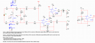
This is way more than just a power amp replacement. It's the full source-select, tone control, RIAA, VU Meter driver, PSU, everything.
Chewing over the options, I wanted to keep the thing functionally-original, but improving in the process.
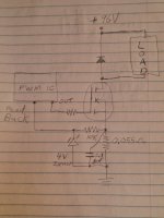
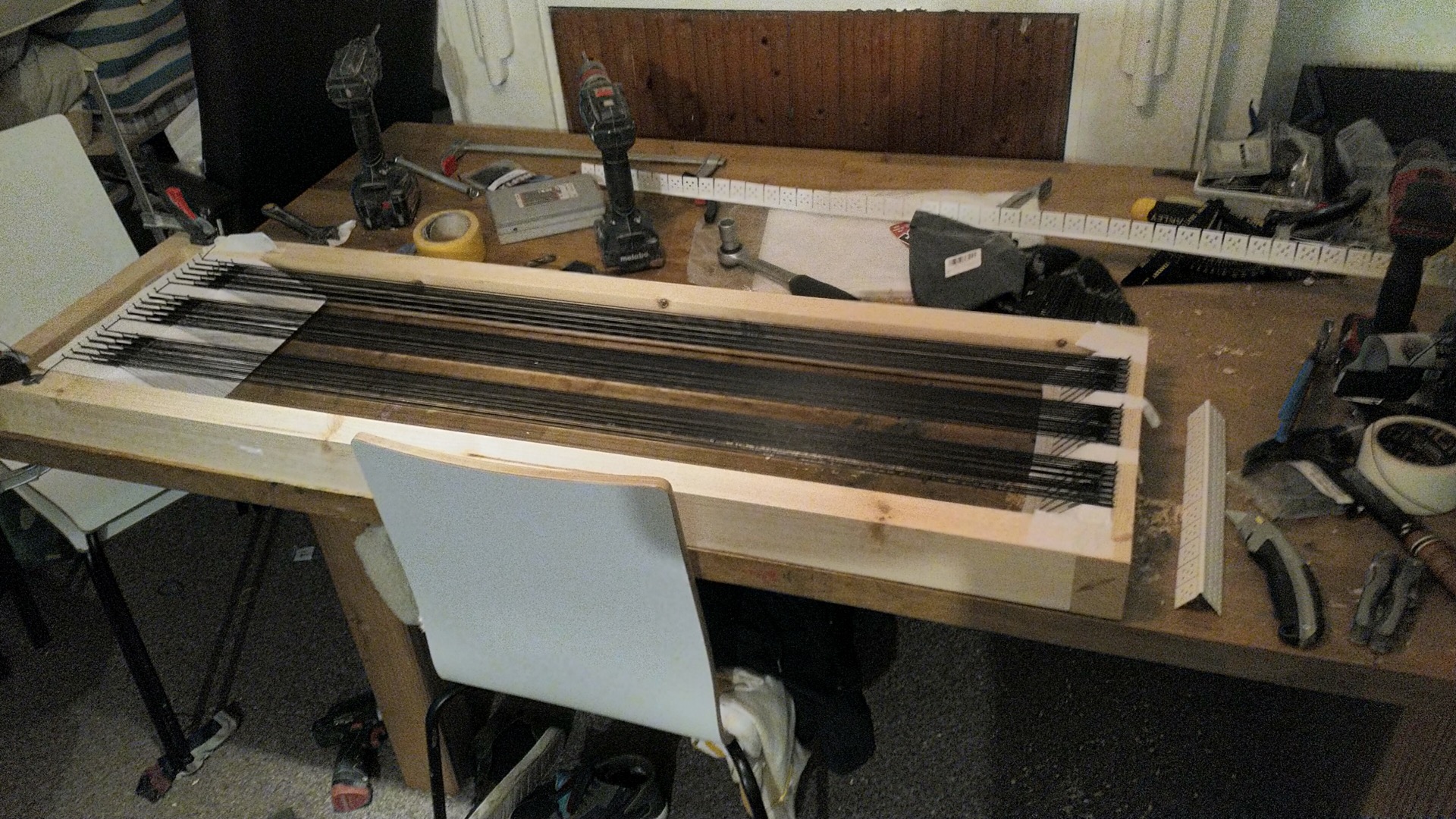
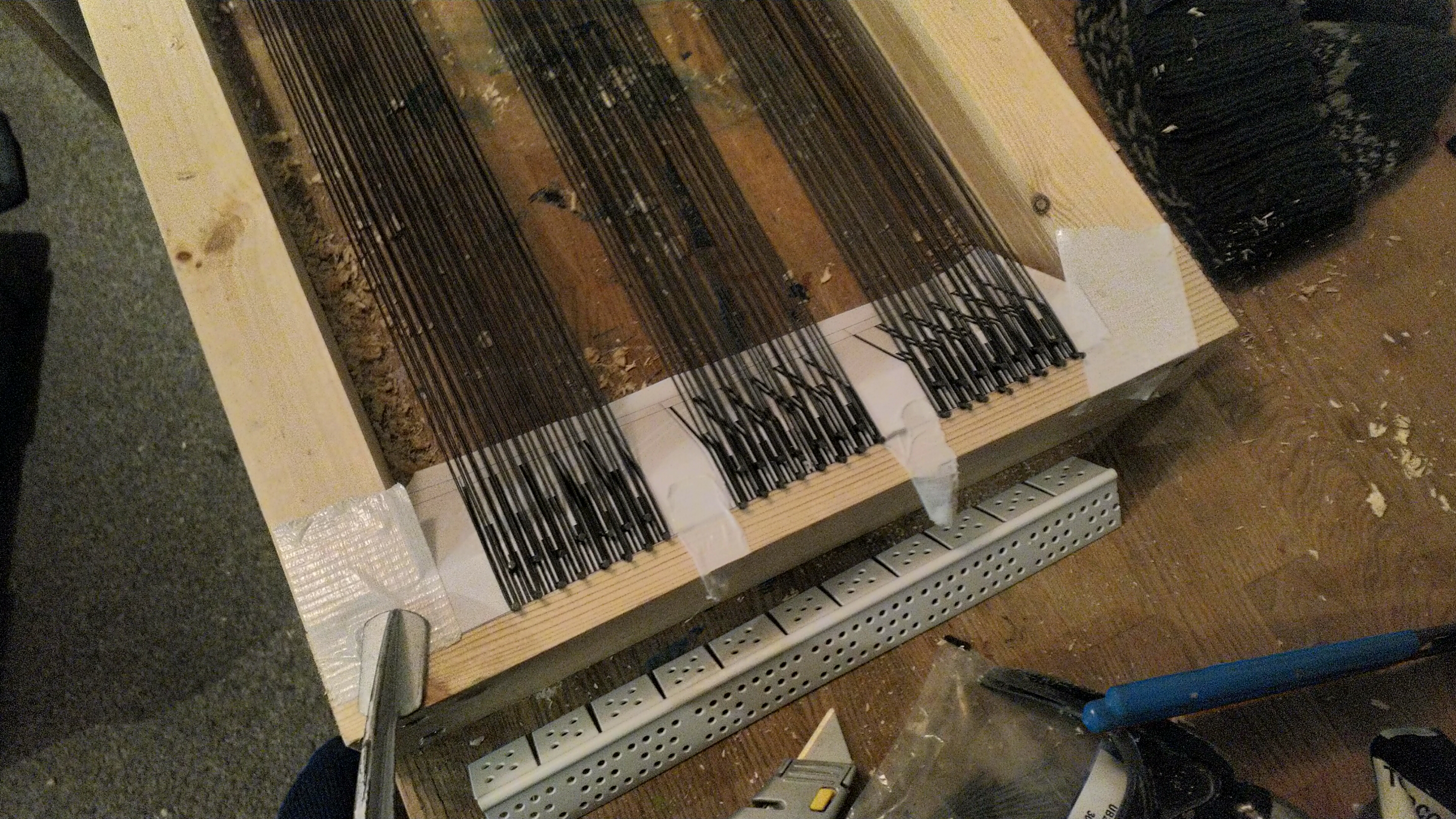
For the Amp, having a nice big transformer and heatsink to play with (the only things left which still works) rules out putting Class-D in there - voltages are just too wrong. Chip-amp was a distinct possibility, but worldwide component shortages put paid to that. Class-AB here we go. For the input selection and tone controls, definitely room for improvement here: everything on the original ran the audio through the front panel pots and switches. Nice when its new, but boy does it age badly. Seriously considered putting a CODEC in there: routing everything in-and-out of digital, but again didn't feel right for the amp. In the end, an analogue tone control processor was chosen. The VU Meter driver was the obvious elephant. Not something I've any experience with, so it took a little googling to come up with something. Into schematic design here we go...
...and about a month later, the beast went live at around 11am this morning!
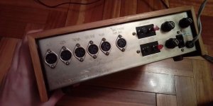
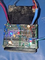
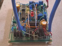
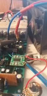
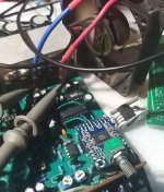
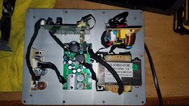
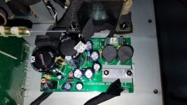
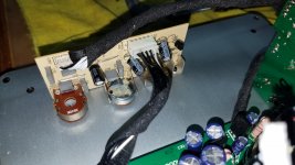
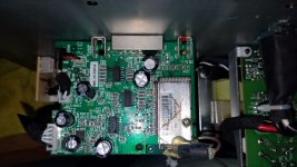
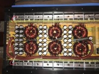
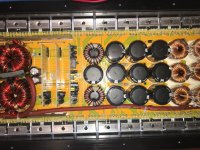
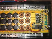
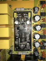
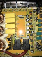
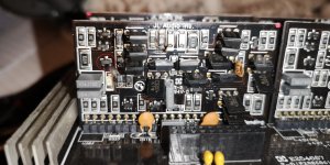
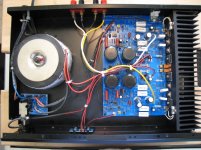
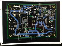
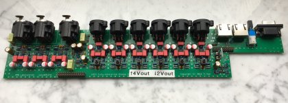
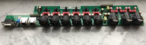
Five PCB's to be precise: Pair of amplifiers at the rear. Mid Left is the PSU board, front left if the VU Meter driver with the Preamp/Tone/select processor on the right (mounted at a 45deg angle to fit).
As for sound-quality, I admit, I'm biassed, but "oh my god" springs to my lips. I mean the old Rotel amp was good, but this thing blows it clear out the water. Quite possibly the best thing I've ever heard: including some decent Denons, Arcams, Yamahas and my previous TriPath experiments (which is saying something).
The amps are based on ESP Sounds P3A schematic, but using different components (and a very different layout). OnSemi's matching-pair MJL3281/MJL1302 output transistors providing the grunt. The preamp is a TDA7440 audio processor doing the heavy lifting. Its driven from a little microcontroller (MSP430) to perform the front-panel reading and parse in I2C. The joy of an MSP430 is that they don't expose any high-frquency digital outside their own chips: even the clock source is integrated. I have put some feeds in for a future IR remote control expansion, but thats for another day.
All in all, it's been over a month of plotting, scheming and soldering, but I'm now a very happy bunny indeed.
* The old Rotel - nice as it is, will be finding a new home soon.
* I'll publish the schematics for the PCBs in seperate posts
* I've also got a whole pile of spare PCBs and a few component sets if anyones interested (UK Postal based)? See other posts...
All in all, I wanted to write this to inspire the love for old HiFi kit and say "don't bin it" - everything is usually possible!!!
Mat


