Source and amplification for Pensil using Mark Audio 10P

I am new this forum. I enjoy speaker building and have done several projects over 15 years, mainly based on 2 way designs (Dayton Audio projects and Madisound kits). Most recent is the CSS Criton 1TDX.
I am very intrigued by the idea of a full range driver speaker not using any kind of crossover network. I mainly listen to jazz, acoustic and "unplugged" popular music. I was thinking of the Pensil 10P as my foray into this world. I have enough 3/4" baltic birch (bought before the war) to make the enclosures. I would actually veneer thick (about 0.20") quarter sawn white oak in a vacuum press, making the panels even thicker and stiffer.

I have read that the Alpair 10P is "sensitive" to the choice of upstream components. In my case, my sources are a Rega Apollo CD player and Blue Sound Node, feed into a Schiit Audio Freya plus, feeding two Schiit Aegir amplifiers. Would this be a reasonable set up?

eBay: Q11 Dual ES9038PRO ES9028PRO DAC Super Decoder (2021 Version) HELP!

Hello everyone.

I have an aged Aragon D2A converter, as well as a (roughly) 12 year old eBay board purchased on the suggestions here at the time. I will probably finish that up as well, but I put the brakes on when I found this eBay listing. I like what I see, as far as board layout is concerned; they offer the proper power supply board (separately), which I would stick in another box with transformer(s), and pricing seems decent to me. Dual mono via completely separate chips; ganged together. Balanced output is attractive to me as well. The only "upgrade" offered is the "better" clocking module. I'd probably splurge for it, because I'm trying to get to a "last" DAC for me and my CDs.

Has anyone built, and more importantly HEARD one of these boards? I don't see much room for improvement in the components chosen- at least not enough to warrant removal and replacement. But, is it a good implementation? I can't tell- digital is well beyond my capability.

This will not be a "cheap" build, so I'd like some guidance from those more deeply nested in the digital decoding world, before I start ordering parts...

Listening tests of TDA1541A vs S1 vs S2

Yesterday, we (4 of us) finally have time to do some listening tests on:
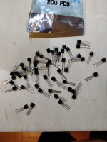
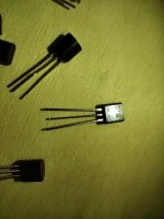
TDA1541A
TDA1541A S1
TDA1541A S2 (a real one, not a fake 🙂 )

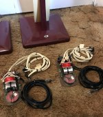
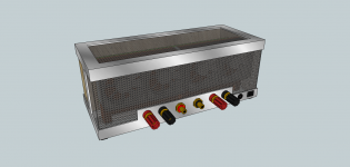
in my modified NOS CD960.

The tests were done blind, so needed to teach my GF to how to pull and insert the TDA1541As, that was very very scary :bigeyes:

The sound:

In conclusion, the normal chip has the most energy, the S2 is the softest, S1 is in the middle. Texture details were pretty much the same.

For pop music, the votes were divided, 2 of us prefered the S2 version and one liked the normal version, the final one liked the S1.

For jazz music, again the votes were divided, normal and S2 received 1 vote each, except S1 received 2.

For classical music, 2 prefered the S1 version and 1 liked the normal version. The final one couldn't decide between normal and S2.

So in summary, the score line is:

.....................Normal......S1.....S2
Pop...................1............1.......2
Jazz..................1.............2......1
Classical..........1.5...........2.....0.5
---------------------------------------------
Total................3.5..........5......3.5

As you can see, the results were a bit of surprise for us :hot: , we thought that the S2 should win hands down, but I guess you just never know what will happen in blind listening tests.

So "in our system" with "our ears", overall we prefer the S1. Of course, this is by no means conclusive.

Wouldn't it be nice that one can switch between normal, S1 and S2 on the fly ... 😀

P.S. Just a side note, to be perfectly honest, when the tests were done blind, the difference in sound was quite small, I really would not lose any sleep over it, whether my system uses a normal, S1 or S2 version. But for now, S1 will stay.

What if IB manifold is too big for wall?

So the question is what can you do when your manifold for an IB sub is too big for the wall space available? In the particular situation I am looking at the wall in question has built in book shelves and cabinets over most of the area. Of course you could remove the cabinets or bookshelves but the powers that be would be unlikely to approve. So there is several inches of space below the cabinets. So one wonders if you could use that space as a snout for entry. It would kind of resemble an odd slot loading or a bandpass of sorts. I am not sure how to model it in Hornresp but perhaps something like a MLTL but only the port enters the room.

Thoughts?

NAD 502 does not spin-up

My 20y? old NAD 502 has developed a problem: after closing the drawer, with or without CD, nothing happens. No spin, nothing. After a few seconds the drawer opens itself again. This problem increased over time and now the issue occurs all the time.
I cleaned the lens, with no effect.
Any suggestions what to do?
I know it’s not economical to spend much money and I’m not sure I would go down the route of exchanging the entire laser unit. However, there is some emotional value in the old NAD….
Thanks!

World's first precision mechanism for CD/SACD/Blu-ray - JMF Audio BDPM1

What about quality and live time expectancy of this unit especially concerning the laser unit (optical pick up) ?
http://jmf-audio.com/dmt37_en.htm
https://6moons.com/audioreview_articles/jaysaudio/4/

Long live laser units for CD use only there was not many.
This included only certain models from Hitachi like HOP-M3 (DENON Linn Karik), Sanyo like SF-91 (Cambridge Audio CD-4/CD-6(CDT), Optima Series from JVC, used also in Japan's best available transport JVC EXU-901a - go to
https://www.diyaudio.com/community/...ct-1-ct1-better-than-vam1254-cdpro2lf.149032/
and Philips CDM-0, CDM-1, CDM-3 and professional versions of CDM-4.

By far the shortest lived laser units were those from SONY KSS-series, even such from top class cd player devices like SONY ES series and Accuphase (e. g. KSS-272A, KSS-274 KSS-190A).
This is the reason, why retail prices for NOS versions (new old stock) are up to € or US-$ 2,500 (!!!).

A friend of me want to buy a SACD capable CD player and have heard from others, that models from brands like e. g. Shanlin Ayon, McIntosh, Project despite very high purchase prices are very unreliable.
The reason therefore is the fact, that the equipped mechanism parts, especially the optical pick up it is the cheapest available for the mass market - check out this URL's:
Price replacement parts:
https://www.ebay.de/itm/265606415758?hash=item3dd760458e:g:JpcAAOSwPLFiOHOk
https://www.ebay.de/itm/265604093786?hash=item3dd73cd75a:g:cYMAAOSwUnJiNpOQ
https://de.aliexpress.com/item/32415646038.html
used in CD-PRO 8 from StreamUnlimited
https://www.project-audio.com/wp-content/uploads/2019/04/CDBoxRS2T-EN.pdf
https://www.audiosciencereview.com/forum/index.php?threads/lets-talk-cd-players.9104/page-6
Login to view embedded media The fact that the mechanism's backing plate was replaced from a solid block of metal milled from the solid, doesn't extend the lifetime of those parts that are in use in a DVD player that costs less than lunch.

Post #4, #6 and #8 under
https://www.diyaudio.com/community/threads/streamunlimited-dedicated-to-high-end-cd.337527/
don't gives little hope, that the situation here will improve again especially in order to SACD playback.

But maybe the transport mentioned in the headline is like one know it from earlier times of the CD era - possibility there are some experiences in the meantime. Thanks for comments.

P.S.: I would still trust JVC the most here, since older DVD players from this brand also have no problems with short-lived laser units (and vintage cd player models from this brand with OPTIMA units also still works).

2 Way SB15MFC-08 + SB26STC-04

Hi all,

Just want to share my speaker project, a small 2 way ported using 1x SB15MFC-08 midwoofer and 1x SB26STC-04 tweeter.

The box design is using 9-10 litres MDF 2.5 cm thickness, with dimension 19x35.5x28 cm (WxHxD), port dimension is 4.3 cm inner diameter and 17 cm effective length giving a box tuning of 45 Hz (you can adjust this to higher fb, around 50Hz, to get a better midbass definition by adjusting the port length). I do flare the two side of the port. Damping using 1 cm felt inside the box except the front side panel, you can add a little wool or anything else by experiment. Simple square bracing between tweeter and woofer, chamfering the woofer inner cut to give woofer a better airflow.

The crossover is using 2nd order electrical and acoustic with acoustic crossing point around 2.5Khz. The phasing is not good, but the frequency response is still within +/- 3dB as you can see at the attachment. Measurement done with microphone on axis to tweeter with a 25 cm distance, since my room is not good for measurement. To give you some idea about the off axis peformance, i measure it around 20-30 degree off axis response (black = normal on axis, red = tweeter polarity reversed, yellow = 20 degree vertical off axis, blue = 20 degree horizontal off axis). I use series resistor to level the tweeter and woofer. Baffle step compensation circuit is used to compensate around 2dB.

Speaker impedance you can see as attachment. Speaker placement can be tried to some 50 cm from the wall. The speaker attend Indonesia Loudspeaker Design Contest (IDLDC) 2017, but got lost there. So, here i share them.

Regards,
Roy

Attachments

  • Frequency response.jpg
    Frequency response.jpg
    333.5 KB · Views: 1,302
  • Woofer Tweeter.jpg
    Woofer Tweeter.jpg
    375.7 KB · Views: 1,228
  • Speaker Impedance.jpg
    Speaker Impedance.jpg
    222.2 KB · Views: 1,334
  • P_20171124_132256.jpg
    P_20171124_132256.jpg
    268 KB · Views: 1,306
  • P_20171124_131349.jpg
    P_20171124_131349.jpg
    353.1 KB · Views: 2,154

For Sale Vintage Transistor and IC manuals Free for shipping

Hi, I am cleaning off shelves and have two RCA Transistor manuals, two National Semiconductor Linear IC manuals both from 1980, and one Motorola Power Transistor data book. All are at least 40 plus years old. Free to a good home you pay USPS Flat Rate shipping via my PayPal account. They are boxed now and ready to go to some semiconductor historian. Smile. My vision is simply too poor to enjoy them now, so they can be yours. One of the RCA manuals is rough, but I think it is complete, likewise one of the National books is a little rough, but complete; the two National books may be very similar.

Scott Henning
shenning@durango.net

LM3886 voltage drop

Hello all. I was given a toroidal transformer (VTX-146-160-224) that has 24v secondaries. I thought I would use it to build a gainclone. I purchased a couple of the cheap XY boards and made modifications suggested on this forum. I'm also using one of these:

https://www.amazon.ca/gp/product/B0828FCC5L/ref=ppx_yo_dt_b_asin_title_o00_s00?ie=UTF8&psc=1

My rail voltage after the rectifier board is about 39v. I'd like to bring the voltage down a bit and was wondering if I could use a premade step down converter like this:

https://www.amazon.ca/gp/product/B07X8XPXP7/ref=ppx_yo_dt_b_asin_title_o00_s00?ie=UTF8&psc=1

If so, would I place these after the rectifier board or would I need to drop the voltage before the filter capacitors? Sorry, this is all new to me so please excuse my ignorance.

Would it be better to use an LM317 regulator (with a power transformer) to reduce the voltage?

Thanks so much!

Allen

NHT XdS monitors and stands, passive xover

Checking to see if there's any interest here in my NHT (Now Hear This) XdS monitors with matching stands in excellent condition. I assembled some passive outboard crossovers based on John Krutke's (Zaph Audio) network that he developed for them. These monitors were part of a flagship fully active integrated system (with subwoofer) that retailed for $6,000 originally and was awarded a Stereophile Class A rating back in the mid 2000's, check the review online. My outboard crossovers are not pretty but they do the job and sound good (Clarity Caps, 16 gauge inductors, Lynk resistors). Midrange is particularly good with the SEAS Excel W15 magnesium drivers ($242 EACH at Madisound!). Just a different phase plug and shielded motor on these. You'll likely want to pair a sub with them, bass rolls off early with 5" drivers in a sealed cab. Shipping probably expensive, they are not puny lightweights by any means. EACH speaker and stand weighs ~45 pounds. CONUS only please. Asking $400 plus actual shipping cost from 64024. Excellent speakers, just trying to fund some other projects.. I do have the original boxes somewhere in my basement.

Attachments

  • IMG_0468.jpg
    IMG_0468.jpg
    461.3 KB · Views: 216
  • IMG_0469.jpg
    IMG_0469.jpg
    401.3 KB · Views: 198
  • IMG_0470.jpg
    IMG_0470.jpg
    361.1 KB · Views: 207
  • IMG_0471.jpg
    IMG_0471.jpg
    765.6 KB · Views: 199

JBL 2245H 18" Bass unit in a "Transmission line" enclosure

This would make for a very large cabinet which would not be an issue for me, but I would be very interested to learn if anyone has built one based on the JBL 2245H 18" Bass unit or a big TL using a similar 18" driver.

PMC use the 15" Volt (RV3363) in the large BB5 system, which has an fs of around 29Hz. The line length is effectively 4m or 13' according to PMC the actual physical length is a bit shorter at just under 3m. Using 1/4 wave criteria works out at approx 2.9m, so close.

I did consider the bigger Volt RV4564 which has a resonance of approx 26Hz which would offer greater performance than the BB5. Based on the BB5 specs 1/4 wave comes out at 3.3m (PMC effective length = 4.6m)

Anyway I am interested to learn if anyone has used the 2245H? I will model with it as a matter of interest.

I happen to have a pair of 2245H drivers doing very little, so propose a stereo pair of enclosures.

Trying to repair my NHB-108 clone

I bought a Dartzeel NHB-108 clone from AliExpress (Queenway) a little more than a year ago. It sounds absolutely fantastic, and I have been really happy about the purchase.

However, one channel has started to fall out from time to time. Sometimes it happens after 2 minutes of listening, other times it will play for hours before failing.

Seller has asked to me adjust bias and check the output transistors.

But... Since its a dual mono construction and one of the power LEDs has stopped working as well, wouldnt it make more sense to check the left channel PSU? I am tempted to just try swapping the PSU from one channel to the other to check if that will move the problem to the other channel.

1448590698275397531.jpg


The LED is always off, so it doesnt follow along with the sound coming and going. But its the same channel.

Any chance to modify 100v line amp to low impedance amp?

Hello,
I had bought G+M GM-1050 100v line amp with built in digital FM tuner. I can even get usb player module for it.
It was a bargain for 30EUR, I was buying it for the the casing, but now I`m thinking... This thing looks quality, it`s Swiss made.
Is there any way to modify this for low impedance speakers without transformer? 4 or 8 ohm...
This is my first time looking into 100v line amp.
I get no continuity from speaker terminals towards amplifier board... even with amplifier turned on.

I can`t find schematics, will post pictures to get an idea...
Pictures will be there in 10 minutes, I need to get home first...

Thank you

Need help figuring out servo for LM3886 with gain of 10 in LTspice

I have tried multiple values for resistors and filtering capacitor, but I don't get correct offset at the output, and filtering is not giving me needed results. Attached are LTspice schematics and LM3886 model.

Two screenshots are showing correct and incorrect frequency responses for the servo filter.

Attachments

  • servo-1.PNG
    servo-1.PNG
    23.4 KB · Views: 187
  • lm3886-servo.asc
    lm3886-servo.asc
    7.2 KB · Views: 75
  • Model.zip
    Model.zip
    3.3 KB · Views: 102
  • servo-filter-incorrect.PNG
    servo-filter-incorrect.PNG
    22.9 KB · Views: 150
  • correct-freq-filter.PNG
    correct-freq-filter.PNG
    26.9 KB · Views: 155

  • Poll Poll
LUXMAN D-03 CD Player

schematic - service manual

  • technical

  • schematic

  • service manual


Results are only viewable after voting.

I have this CD Player
A very nice and scarce LUXMAN D-03 ( laser toshiba OPH-32 )
But out of order : It no longer recognizes the presence of CD discs.
Knowing that the laser is still shining, I think it is still alive and its problem is located on its servo card.
Unfortunately, as I do not have any technical document, and without schematic diagram, I am stopped to repair it.
If somebody have these or its service manual...
And infinitely grateful if you could help me.
I would be happy !!
Please, please
Thanks from France,
Raymond

Pardon me for my poor English


DSC_0266.JPG
aymond

Synergy horn and general questions

How does a the air energy from the bass woofer of a synergy horn, reflecting back into the cone, not cause a ton of distortion? As the holes in the horn for the 15" woofers seem far too small, inadequate in size to allow a proper amount of air to pass through to avoid said issue. For near and midfield listing, is there advantage to horn loading woofers rather than having an array of multiple midrange drivers around a tweeter on a flat baffle to achieve the same coaxial effect? I get an increase in sensitivity is achieved though if using an active crossover, who cares?
  • Like
Reactions: DorinD

New Issue Avatar idea

Is the color of the background behind the user initial a random color, or has it some meaning? If random, I would recommend to give it some meaning. Some ideas:
Time since registration: greeen = less than 1 year, yellow = less than 5 year, red = less than 10 year, blue = more than 10 year.
Or it could refer to the geographic location (continent: Europe, North America, Asia, etc.)
Or it could refer to the number of posts since registration. Or it could indicate the time since last seen online (green = currently online, yellow = online in the last 24 hours, red = online in the last week, etc.)

LM317 Loading

Hey, Ive just designed my own LM1875 based amplifier thats fed by a SMPS through a filter PCB. On this filter / regulator board i have 2x lm317, one set up at 32v and another at 12 with both of these having a voltage divider to provide a bias point for the TL071 and LM1875 on the amplifier.

I've noticed that the 16v (VD 32v) output are only putting out between 5 and 11v depending on the position of the 10k pot on the amplifier board. I assume the Pot is changing the load on this? Is there a way or a change i can make to the PSU filter board to stop this loading occuring? I'm getting reduced output as i get asymmetric clipping due to a low bias point on the LM1875. Sorry for the handwritten schematic 🙂

Whiteboard.png

Keithley 2015 THD no generator signal on Ouput 1

Hello everyone,

I have a problem with Keithley 2015 THD. On the first output of the generator, I do not have a sinusoidal signal, but on the second channel I have both a sinusoidal signal and pulse (of course, switched not at one time). What could be the cause of the fault? Is there any service documentation with diagrams of this meter available? Where and what should I measure?

I bought this meter as used. I wonder if by connecting a signal from the generator to the tested equipment and at the same time having a connected oscilloscope, with a short circuit with a PE wire, it can work correctly? Could such damage occur as a result of a short -circuit of the negative potential of the generator with the Protective Power of the PE? The easiest way to write a question is: can the generator output sockets be connected directly to the PE protective cable? Because I noticed that they are factory isolated from the metal parts of the meter housing and probably for a specific reason.

I want to measure the harmonic distortions of the audio amplifier channel with this device. So I want it to work in the loop without using an external generator, because I think that the internal generator will be the most precise and most tolerated, thanks to what the meter.

What is your opinion on this matter? How is it best to measure audio signal distortion with this meter?

Greting
Aleksander

Driving this reverb tank with a tube, pointers requested

I'm looking to drive this tank pulled from a 1990s Ampeg with tubes (originally driven by solid state). I don't know the input impedance, but the input DCR is 30 ohms. In the amp I'm modifying, I have a single 12AX7 section and a 6AU6 to play with. A little reading tells me driving the tank from the pentode plate may be a good way to go (then using the 12AX7 triode for gain recovery.) What I don't know is what current/voltage I can/should put into the tank, and if I have to be careful about burning out the input coil. Help appreciated!

IMG_0279.jpg
IMG_0280.jpg

Keep Moving - Documentary Feature from long Time DIYAudio Member Salar

I have very rarely posted on DIYAudio the last three years.
I had finished my feature documentary about dancers in the GDR and their life
under the communist regime.
So "Keep Moving" has several meanings - not only to move as a dancer
but also to get over the Berlin Wall, getting used to Western society
and to adopt to changes in life - because in a dancer`s mid-thirties
his body is literally worn out -he is forced to find a new job and establish a new life.

Being a film editor and sound designer for 30 years,
making a feature length documentary is nothing new to me.

But Keep Moving was also my debut as a producer, director, cameraman, sound mixer.

The result seems to be fairly good as I was invited to the
Berlin International Film Festival, Berlinale -
one of the most renowned festivals worldwide -
as well as on other festivals.

Not bad for a feature made without
any funding and edited and mixed in my sleeping room - DIY

Keep Moving is available here:

fishermansframe.gumroad.com/l/abtyf

with subtitles in English, Chinese, Spanish, French, Greek, Polish.
When you click on the film poster, you can also watch the trailer.

All the best,
Salar

15W or 18W Revelator in a small room?

Hi!
I would like to build a (small) 2-Way-Speaker from a proven Design.
I choose the Revelator Woofer because I would like to listen a bit more an the "beautiful side" - and prefare actually Classical Music.
I only got a small room 3,5 x 4,5m and its not a dedicated listening room 🙁
Listening distance is small 1m or 2,2m
The Speaks will stand right in front of the backing wall.

My question(s):
What size of woofer should I choose: W15 oder W18?
(I would prefare w15 because I would expect it has enough bass for me but delivers a finer midrange)
Which are your favorate designs for the SS woofer?
(I live in Deutschland - the American Designs, for example from Meniscus are complicated/expenive to order for me)

Thanks and bye
Rundalf

Germanium amp instability

So I've been playing with a design using old soviet germanium transistors and running into a stability problem. This is the schematic that I prototyped with all values the same except using a P602 transistor for the VAS stage. The instability happens when the voltage is increased to a certain level, say 20 volts. It breaks into oscillation and the current spikes along with lower output transistor getting warm. With a speaker it sounds like static and looks like random noise on the scope. I tried 100 ohm base resistors on the output devices and large and small power decoupling caps but nothing makes a difference. Finally managed to catch the start of the oscillation with my scope across the base resistor of the lower output transistor. Who knew these slow leaky GE devices would be oscillating at a few Mhz.

Attachments

  • IMG-2421.JPG
    IMG-2421.JPG
    378.7 KB · Views: 191
  • JLH-LH-Ge-AB-2.gif
    JLH-LH-Ge-AB-2.gif
    14.8 KB · Views: 200

  • Locked
For Sale First Watt DIY F6 Amplifier

Hey buddies!!

My diyaudio first watt f6 amplifier will is out for sale, it was assembled with up most care and sounds great, Lol damn great!!. All the component were sourced from diyaudio expect the chassis, it has more heat sink area than the first watt f6 chassis and is very high in quality.
Little description of the circuit: This F6 is a class-a mosfet power amplifier, with a jet driver stage, It utilises small signal transformer for the phase inversion, so both the output mosfet are n-channel,. However, this transformer greatly contributes to the overall sonic character of the amp which is very highly regarded and considered to be similar and having all the benefits and positive characteristics of a tube amp, and making some observers speculate that much of the positive (tube amp ) sound is the transformers, not the tubes. Lastly, the f6 is a regular kind of amplifier- a voltage source amplifier, which requires nothing out of the ordinary from the preamp or the speakers. Also, the power output is 25wpc into 8 ohm. 50wpc into 4 ohm.

I think this little description might help!!!
PRICE: USD725
SHIPPING WEIGHT: 35.00(lbs)
Mint condition and function well.

Difficulties with SEPIC converter

Hi,

I designed the following SEPIC converter for experiments with the solar panels I'm soon buying. The schematic diagram, both copper drawings and the assembly drawing are added to this message. The solar panel system I spoke of consists of two 100 W panels (Voc~20 V, Isc~10 A), so one knows pretty sure the worst case conditions. Basically, you cannot draw more current from the panels than the rated short circuit current is.

Anyway, this converter works perfectly when there is a small load at the output (the output voltage is set to 14.4 V). But when I start to draw more current through the converter from a 12 V test supply, an irritating noise appears, and it gets louder as the current increases. So I thought the inductor core must be saturating. It isn't maybe made clear in the schematic, but the two inductors are wound on the same core, E42/21/20 with approx. 3 mm air gap (quite large one). I tried to simulate and calculate the inductors and core to withstand maximum of 10 A, but something has gone wrong. The inductors consist of 15 turns, two 1.2mm (diam.) enamelled copper wires wound parallel.

I fear I have made one crucial mistake: I salvaged this core from a defective SMPS, and it might be that the ferrite core itself is permanently magnetized and therefore saturates far more easily. I could fix it if I heated the core above its Curie temperature, but since that isn't an option, I guess it's time to make a new inductor set. Could there be any other reason for premature saturation? Thanks for opinions!

The schematic

The bottom copper

The top copper

The assembly

Bias problem Marantz PM-94

I could do with some help with fixing my PM-94. 🙂

The Marantz has been recapped and all solder joints expected. It appears to function well however there are the following problems:

1. The left heat sink gets really hot while the right one is much cooler. The first step of biasing the left channel to 36 mV is possible, however the second step of biasing to 180mV not (initially it appears to work when turning the trimmer, but then it jumps back and forth in value).
2. Biasing the right channel works in both steps, however the heat sink gets warm but not hot. My feeling is that it's working in class a/b (perhaps this could be related to the quarter A settings?).
3. Have some difficulties to get the DC offset set to 10mV (and it seems to fluctuate).

1. What would be the most likely cause for this erratic behaviour of voltage jumping to different values?
2. Could the quarter A settings cause the right channel to work cooler (in class a/b) while bias settings in both steps are set to resp. 36mV and 180mV?
3. The DC offset changes with the bias and is difficult to keep at 10mV in the right channel. Any idea what might cause this? (am able to set it to around 8 or 14, but then it changes)

All tests were done at least after one hour.

Hopefully someone can point me in the right direction. :spin:

Attachments

Coil winders

I've been looking into getting a manual coil winder mainly for making my own inductors but apart from the usual Chinese ones it seems that there are not many options, especially in Europe.

Can you recommend a decent winder new or used, ideally with a tensioner?

These AVO look great but I guess it's pretty hard to find one.

Thanks!

Attachments

  • DSC01586a.jpg
    DSC01586a.jpg
    167 KB · Views: 146

Phono Pre Amp Loading With A Step Up Transformer

Hi there and thanks for stopping by.
I built a phono pre using 5842 tubes designed by Joe Tritschler. I'm using it with a Yamaha MC-1s cartridge and a SUT I also built using some Shure audio transformers. It sounds very good. Quiet, revealing, and steady through most all of the frequency response except that it lacks some bass authority. It does not lack much at all and I am wondering if using the step up transformers would change the loading the cartridge wants. Without plugging in numbers, can anyone tell me if this is a credible theory and maybe give me a little bit of theory I could use to figure out possible adjustments?
Thanks to anyone who might take the time to help.

Newbie questions

Hey all, I have decided on a FAST/WAW setup ( = full range -ish speakers + subs ) and I am currently thinking out the amplifier part of the system. I'll be trying my best at a B1 preamplifier DIY prefab kit designed by Nelson Pass, which utilises the Korg NuTube. Schematic is attached. This will be my first amplifier building project ever. Hype is real!

I understand the bare basics of passive crossovers but I'm new to amplifier design and I have no friends with relevant knowledge on the subject matter, thus I present the following questions to whomever of you would be so kind as to lend me their knowledge 😊
  • I have a 100k variable resistor pot that I would like to use instead of the 50k pot that comes with the kit. Could one just swap it out? What effect would it have?
  • With the goal of a WAW setup in mind, I'd like to connect a power amplifier (main speakers) and also a DSP unit + subwoofer amplifier to the output of the preamp. Does this change (or halve or double) the required value of the output resistor (for example 2 times 50k) ? Or leave it like is? What effect would it have?
  • In order to add the effects of a 1st order line-level passive high-pass crossover (LLPXO) to the main speakers, should one simply add a capacitor in front of the 100 ohm resistor (and tailor the value according to the 100 ohm load it sees) ? Does that affect the signal that the DSP unit sees or needn't we worry about that?
I can't wait to order a kit and get soldering, I hope the setup I have in mind can be realised with a small set of modifications

Have a nice day, thanks in advance, cheers

Attachments

  • schematic.png
    schematic.png
    54 KB · Views: 143
  • schematic question mark.png
    schematic question mark.png
    7.4 KB · Views: 143

Yamaha G100 Channel A preamp into TDA 2030 power section

Hello,

I am relatively new to transistor electronics though have been working on tube amps for several years.

I have an 80s Yamaha G100-212 III amp which has an incredible and well-known clean channel. I've attached the schematic. Would it be difficult to take the simple preamp (Channel A) section of this channel and match it with a TDA2030A or similar power section to make a small form factor clean guitar amp?

I am building a small amp from Nightfire Electronics that uses this power section for which I have a schematic as well.

Any help appreciated

Doug Frenia

Attachments

Vintage HiFi 60/4 speaker kit - midrange issues

Being one of the best sounding speaker kits back in 1983's one can make - or so they claimed and it had a good reputation. It was called Hifi 60/4 (meaning 60 litres and 4 drivers). Vifa P21rex woofer, Peerless KO40mrf mids and Dynaudio D21 tweeter. The thing is designed to give smooth overall response in a typical room environment to a listening position as well as to give deep bass response down to 25Hz or so. Crossover freq: 500 and 5000Hz.
Anyway I just finished the first one and took a quick listening session. No, this cant be true, how can one even listen to this speaker as it is? It sounded just horrible! Midrange was badly peaking and one notey. That was not what I was hoping for.
There must be something wrong but I dont know what exactly. I took some measurements from the midranges with and without crossover (measured at 1meter distance).
Here are the results:
ko40_nocross.jpg


ko4_crossed.jpg


Waterfall (some weird things happening):
waterfall.jpg


So as can be seen, it is heavily peaking around 3kHz. Even worse with crossover. Any idea what is going on there?

Here is the speaker itself and some measurements by the hifi-magazine which is the source for this speaker kit.
IMG_20220612_175147.jpg


IMG_20220612_175248.jpg


And finally the crossover:
hifi604crossover.jpg

300W Quasi power amplifier

I have build 2 of these and 1 has developed a fault where after switch on everything is OK and I can leave it with no signal for as long as I like BUT as soon as a signal is applied the standing current goes crazy 10A+. It blows the +ve fuse but not the -Ve fuse and even stranger is that the speaker does not deflect. Also before the fuse blows you would not know anything was wrong judging by the sound from the speaker. Any help much appreciated
300Watt High Power Amplifier.jpg

Scheduled for resolution Difference between bold and normal is too subtle

Hello,

I like a lot the new forum, especially that it's now usable on mobile.
The only thing that bothers me a little bit is the unread topics are in bold, but the difference is very subtle so when some are read between unread, it's s not easy at a first glance to differentiate.
Or perhaps I missed a setting somewhere ? I'm using dark theme BTW.

Thanks

ACA Concept II

This is my second Amp Camp build. Like my first one, this will be a drawn-out affair. However, I’ve got it pretty well planned out and I’ve already made some progress in construction.

My primary motivation for this build was a pair of fan-cooled copper heat sinks I found at the local electronic salvage store a few months ago, which cost me $9 each. I knew I had to figure out some way to put them to good use. The fans are pretty quiet at low speeds, and I figured they would be good for a small ACA build… so here we are.

Unlike my last build, this time I’m going to alter the circuit a little bit based on a suggestion made by Zen Mod in the official Amp Camp thread. I’ll be switching out the IRFP240 mosfets with IRFP150s, “crank[ing] up the voltage,” and halving the values of R1 - R4. That should produce an “ACA on steroids” according to Zen Mod. We’ll see how that works out. If it doesn’t, it’ll be easy enough to swap in the standard components. My plans for this amp are to use it to drive moderately-sized subwoofers, using my current ACA mono blocks to drive a couple of small two-ways.

In order to fit my case design and to keep everything neat & tidy, I’ll be making my own 2-sided PCBs, something I’ve never done before. I laid out the board using Adobe Illustrator:

attachment.php


You’ll note I’ve included circuitry for a mosfet-base fan controller. I’m not 100% sure I’ll be using that circuit, so that part of the board may change.

The heat sinks (with fans) will be connected with a piece of aluminum angle, and the PCB will mount to the heat sinks. Aside from the power jack, switches, LED, and in/out connectors, all the working parts of the amp will be included in this assembly:

attachment.php


attachment.php


The case framework will be made of welded steel. Wood at the front and perforated steel at the top and rear will complete the case:

attachment.php


attachment.php


In addition to the usual metal work and wood work, there’ll be some other fun stuff like etching and plating, so hopefully some of you will find this interesting. Stay tuned…

😀

Edit: If you have Sketchup (and I suggest you download it if you don't), you can download my model here:ACA Concept to .skp model (zipped).

Attachments

  • ACA ver. 2a PCB.png
    ACA ver. 2a PCB.png
    70 KB · Views: 2,427
  • ACA ver. 2a innards front.png
    ACA ver. 2a innards front.png
    67.4 KB · Views: 2,420
  • ACA ver. 2a innards back.png
    ACA ver. 2a innards back.png
    70.2 KB · Views: 2,410
  • ACA ver. 2a front.png
    ACA ver. 2a front.png
    307.8 KB · Views: 2,453
  • ACA ver. 2a back.png
    ACA ver. 2a back.png
    373 KB · Views: 2,394

How to wire my volume pot without killing my amps?

Hello everyone! back in '20 I built an amp which has served me well, I decided to add a volume pot. I added the pot as shown in this diagram and pictures. I connected only one channel at first, it seemed to be working fine, then my amp died!
The amp is this one: https://www.3e-audio.com/amplifier-kits/tpa3251-2ch-140w. The fault light is on now 100% of the time with nothing connected. I don't know if I shorted the input to the heatsink or overloaded it by only inputting one channel.

So, I had a little TPA3116 amp board, I took the time to set it all up as shown in the pictures. I turned it on, the light came on, no output. I had ANOTHER one of these TPA3116 boards, I eliminated the volume POT and hooked it up, and it works. I tried the first one, and nope, its dead.

Something about this pot circuit is killing my amps. I took the meter to it, there is no continuity between any leads ground/signal or L/R. Continuity is present between all grounds. When turned up all the way, there is continuity across the pot at 2.2 ohms on each channel, but not between them.

Are the caps in the right places? Previous advice was to have the input caps on both sides of the pot connected with the negatives to the pot, is that correct? Could a bad pot be causing my problems?

Attachments

  • Capture.JPG
    Capture.JPG
    40.2 KB · Views: 208
  • IMG_20220528_160330.jpg
    IMG_20220528_160330.jpg
    437.1 KB · Views: 195
  • IMG_20220528_160334.jpg
    IMG_20220528_160334.jpg
    454.1 KB · Views: 166
  • IMG_20220528_160347.jpg
    IMG_20220528_160347.jpg
    345.4 KB · Views: 195

Speaker magnet mounted off center

Just received a pair of Peerless 830874 on my doorstep.
https://www.google.com/url?q=https:...0QFnoECAQQAg&usg=AOvVaw1zJ_P1_ueAc2StgwnlBHEJ
One of them has a magnet assembly off center. Not purchase from parts express. Above is just for reference.
This is all I could find in a quick search of Google addressing this ..
https://audiokarma.org/forums/index.php?threads/speaker-magnet-off-center-klipsch-woofer.841026/

Realizing that the polepiece/ backingplate alignment is much more important than the magnet itself, I would still have thought that axial alignment of all parts of a speaker would be more critical than this. It's not really a 'cheap' driver either at 53usd.

Sorry for the bad cell phone pic. The edge to edge of the backing plate and magnet is 5mm on one side and 10mm opposite it. Is this a concern? The glue on the inside between the cone and the half roll in this one, compared to the other, is REALLY sloppy as well. Did I just get a factory second here?
IMG_20220612_083342698_HDR.jpg

Learning to build boards for vintage equipment.

Hello, I'm trying to learn about build little boards for some of my units that are messed up.
This boards are not that complicated compared with the usual ones that I see here, they are single side and usually semi burned, with broken pads and traces or several repair attempts.(hacks). These have been a hobby of mine from a while now and I have a ton of fun rebuilding them.
For that purpose I'm using easyeda, I find it easier to learn than KiCad or Eagle, but since I'm hook and kind of obsessed with this I'll learn them along the way.

With that said, I made a first one, is for the power supply of my Sansui BA5000 and I wonder if you guys can point me if I'm in the right direction. Basically I made a ground plane on the bottom layer and else on top, but since I'm barely know what I'm doing be brutal, if my layout is useless I have no problem starting again with some pointers. That how I learn.

Cheers.

Attachments

  • F2421.jpg
    F2421.jpg
    433.1 KB · Views: 160
  • F-2521 EasyEda.JPG
    F-2521 EasyEda.JPG
    331.7 KB · Views: 158
  • f2521 3d.JPG
    f2521 3d.JPG
    227.9 KB · Views: 167

Problem with Led Vumeter

Sometime ago the white smd leds that works as dB signage of my mastering AD/DA converter start to burn out. When only some few remains from 32, I decided to replace them.
I got the smd leds values from a source and found an equivalent, due the original part is not in production anymore.

I checked polarity and I was a bit confused at the beginning, but proceeded with soldering. When tested the unit, all leds, included the VU ones (green-yellow-red) lit without any sound signal. Not full bright but enough to realize something was not ok. Needed to buy a mignifier glass and analyzed the circuit with a better eye, and understood that I need to solder the leds the other way around. Desoldered all, and the white leds shine better, and the VU leds lit barely standing still. Injected signal and for my surprise the white leds lit but instead of permanently lit from 40dB to 0dB as it should, they act as an inverted VU, that saying that depending on the decibels the VU leds lit and increase in the scale, these white leds turn off in sync. Exactly as a negative mirror of the VU.
I asked for the schematics to the manufacturer of the unit, but they stated that disclosing schematics is forbidden. So I draw one myself the best I could.

Can you guys help me find out?

Attachments

  • Vu_Schem_v.1.0.jpg
    Vu_Schem_v.1.0.jpg
    333 KB · Views: 123

Williams Ring of Two Current Source

This current source was first described by Peter Williams in the July 1967 issue of Wireless World and is shown in the first schematic. The most commonly used variant replaces the zener diodes with leds as shown in the second schematic. Williams himself noted that it is theoretically possible that the circuit may not self start, indeed I suspect that most simulations will not self start without a "kicker" resistor. However, in real life, the circuit reliably self starts regardless of ( within sensible limits ) voltage, current, temperature, transistor matching, deliberate transistor mismatching, and the presence or absence of light. I have verified that the circuit self starts at -20C, so if the circuit is kicked into life by leakage current through the transistors it must be very small. In addition to the tests I have used this circuit as a two terminal current source in a myriad of amplifier projects over the last 20 years with no problem.
My questions then are:- (1) Has anyone observed this circuit, or a variant of it, failing to start and (2) Has anyone got a convincing explanation, other than miniscule leakage currents, as to why the Williams ring of two current source always starts so reliably.
Finally, in the third schematic the leds have been replaced with transistors and this circuit too, self starts reliably. I find that two terminal current sources make pcb layout easier and this variant has very good PSRR, potentially very low noise, and fairly low temperature sensitivity. I'll switch to using this variant rather than the led version.
Any comments, particularly as regards shortcomings of this circuit are welcome.

Attachments

  • WilliansRingOfTwo.png
    WilliansRingOfTwo.png
    13.9 KB · Views: 1,076
  • WilliamsCcsLed.png
    WilliamsCcsLed.png
    5.3 KB · Views: 977
  • WilliamsCcsTr.png
    WilliamsCcsTr.png
    6.8 KB · Views: 971

Router options for speakers

Hey Guys,

I’m about to build my own speakers, and I’m in need of a router for the driver holes. The wood is 40mm thick ply. I plan to first route the recess for the mounting flange to mount the drive flush , and then cut out the holes for the drivers. After that I may do a 45 degree chamfer.
so I’m contemplating what router to get.
this will be my first router, and I don’t know when I will build the next set of speakers. Any suggestions, like what power rating, corded or cordless, other tips?

as a note, I don’t mind renting one before purchasing, but I’m assuming that I still need to get new router bits and templates .

Volume pot upgrade for original tu8200 and tu8500

Hi apologies if this has already been answered, just wanted to double check because there are many different versions now.

I have the original tu8200 and tu8500.

My tu8200 volume pot is noisy and id like to replace it. What is the best volume pot upgrade for this version of the amp? I am ok to solder wires point to point if needed.

Also, is there an upgrade option for the tu8500 volume pot?

Thanks

Pioneer SA-508 Very slow start

I'm trying to figure out what could cause this. I turn the amp on and it takes nearly 2 minutes to come on. Very slowly sound and the VU meter comes up.
Happens only if left off overnight. If turned on after an hour or so it's just fine. It also otherwise works normally.
At first I thought it must be the two big main caps as one was slightly bulged. So I've changed both but it didn't fix the problem.
Fuses are not blowing so there is not excessive load so I can't think of what could it possibly be? It must be somewhere in power supply but apart ftrom the main caps there isn't much there to cause problems. I did check surrounding caps but all are ok too. I'd welcome any ideas, thanks.

Highly Respected Speaker Brands

Although I like to design and build speakers I really want a commercially available speakers. Since there really are no brick and mortar stores anymore my primary channel of purchase is preowned or from online retailers. However I recently watched a video of Danny Ritchie absolutely lambasting Vienna Acoustics speaker. It scares the crap out of me that I would spend 6 or 7k on a speaker that is worse than I can make, and I am only a hi level beginner lol. I am looking for a mid size floor stander to use with my GR Research Subs. I will be using CJ premier 12 tube mono blocks. room is 14x22x7. I am looking for a relaxing sounding speaker nit uber detailed. I want detail of course but not the absolute last word in detail. Having a tube amp helps. Also I am wondering if I should consider only 8 ohm versions as tube amps dont deliver huge amounts of current. Again I am mostly interested at looking in to BRANDS. Then I can drill down into models. Thanks

Well first experiment failed ( baf wadding)

Well I tried adding some wool baff wadding to my ProacDT8’s and it made the sound worse

I took measurements as well and while it smoothed out the freq response, what I heard was a less lively and open sound.

i tried different amounts as well.
i first put some behind the woofers. Not too much. And it deadened the sound
then I took that out and put some on the bottom since it is bare around the port. Was a bit better, but again less lively.
i put different amounts in both behind the woofers and on the bottom.
both very little and more didn’t provide hoped for results.
interesting since the speakers box doesn’t have much damping

good learning experience.

Wireworld USB cable wire layout

Hi. Wondered if someone could help
Bought some unterminated wireworld ultraviolet cable for a 10ner to make my own usb cable.
What would say are the cables.
Black and red assume 5v and gnd ?
The other two in the foil signal cables?
What also do you suppose is the third uninsulated wire for?

Thank you. This is my first attempt at usb cable

Attachments

  • Screenshot_20220613-175817~(1).jpg
    Screenshot_20220613-175817~(1).jpg
    229.7 KB · Views: 111

Which Pass Labs amp is this?

I ordered a Cambridge DacMagic 200m from this company:

Service – AVS Oymann

Then I observed a picture of what I think is a Pass Labs amp?
Picture no. 2? ....easy to spot.....Panasonic Mox, Bourns single turn, lots of parallel devices, encapsulated toroid's etc.

But which model?
They don't sell them but seems to be able to do some repair......

The last one seems to be a German company called Brinkmann Audio which I did not know. Very solid look. Could be one of "Cubicincher's" smaller amps?

Marantz CD74(84) CD-R track step problem

Hi All!

I have been collecting and listening to the first series of Philips CD players for at least 15 years.
These are for me: Philips CD100 -3pcs, CD104 -1pcs, CD303 -4pcs, CD304 -1pcs and CD304mk2 (diy) -1pcs.
I bought these devices incorrectly and repaired or will repair all of them. In many cases, only the old capacitors caused the fault. However, one phenomenon is true: CD-Rs are read and handled flawlessly.

I also have a Marantz device. These are CD73 and CD74(84). The CD73 is a pretty used piece, but it also read the CD-R. The problem is with the CD74(84). A CD-R disc reads and plays correctly but does not skip the track. I had a device years ago that didn’t like any of the written discs. It's been sold for a long time.

Now we have a CD74(84) again and it picks because there is a CD-R that you can skip through. I want to keep that for now and fix it for myself!
I installed the CDM-1 chassis in a CD 100 and can perfectly track the tracks of all CD-Rs.The error may be somewhere in the servo or decoder panel. I don't know, I haven't figured it out yet. I have already replaced all the capacitors in this as well. Nichicon FW, FG, ES(muse bipolar), KW, KZ(muse). Panasonic FC.
  • Audio Frequency Test Sample Nr.3 4822 397 30085
  • Test Sample Nr.5A SBC426A 4822 397 30096
  • Playability Test Disc set SBC444 / SBC444A 4822 397 30245
With these I set the plate height, the laser current in vain, because the track step error will not improve.
Offset error and focus error will not be eliminated with further adjustment.
I have several Marantz CD74(84) servo panels, but each of them produced a track step error. Maybe there is a faulty part on this panel that will break down on all such panels over time? Where do I look?

Thanks

My English is very weak, but google is my friend. 🙂

stk3156 replace with opamp and VAS?

Idea:
Opamp input stage, followed by a voltage stage gain to get rail to rail swing for the signal so I can ditch the STK unobtainium. I am clearly working above my pay grade here, but I feel like I should be able to figure this out, and hopefully learn a lot in the process. If I'm way out of my element, please let me know.

I acquired a broken Yamaha r2000, with a toasted STK3156 Voltage Amplifier chip. I got another one, and the cheap Chinese crap failed. So rather than hunt endlessly for another genuine STK, I would like to replace it with something more fun. Since I have the Yamaha schematic with voltages at different pins for the STK, it seems plausible that I should be able to figure this out. I could not find a datasheet for the STK3156. With the Yamaha schematic, I see two positive power supply pins, and 2 negative voltage supply pins. One each +-20V, and one each +-86V. I suspect that the +-20V supply at pins 9 and 10 is providing the voltage for the initial input stage of the amplifier, and then there is a voltage amplification stage that is supplied by +-86V at pins 7 and 8. These are Vcc and Vee used to bump up the signal voltage. Output to the power stage is from pins 3 and 5.

Basic idea is, can I take the input signal and run it through an opamp, and then build a voltage gain stage to bring the potential swing of the signal up to the rails. An opamp is compact, and I’m not averse to using to them. Then the voltage boosted signal can pass to the power amplifier section of the amp normally. I could place all this on prototyping pcb board, and stick it in the STK slot. Bam problem solved. The bias for the power output is on the power amp board, as is the xprocessor that decides to use the high voltage 86V rail (+-B on the schematic) or the low voltage 46V rail (+-B1).

So the Voltage amp stage after the op amp would want to be able to swing the signal to +-86V (or close). I would need a circuit for each channel that could do something like the attached schematic. (snagged it from TI website, paper attached.)

Would something like this work at all? Original schematic shows it going to an inverted input, but if I am taking a single output from the opamp, and sending it to the VAS, it shouldn’t matter…. Right? Do I need to add a compensation cap at q3 and q4? Do I just need to go back to school?

Input is coming from the attenuator (volume knob.) I am unsure how to calculate the voltage gain at each step, in order to determine the voltage gain at each stage, to get the output close to the rails. Help would be appreciated. This is my most ambitious modification to a stereo idea to date.

Thanks for any help.

Attachments

  • r2000 amplifier section.jpg
    r2000 amplifier section.jpg
    340 KB · Views: 525
  • opamp and voltage gain.jpg
    opamp and voltage gain.jpg
    87.1 KB · Views: 488
  • snoa600b.pdf
    snoa600b.pdf
    959.1 KB · Views: 142

a better pentode for less!

I have found a way to make an excellent pentode from some real "junk" tubes. Look at the plate curves for any of the dual control pentode tubes (6LE8, 9KC6, 6BV11, 6MK8,6BU8,....)and they are very rounded and high distortion due to screen current siphoning off plate current at low plate voltage. These tubes have a close-meshed G3 (suppressor grid) instead of the very open spaced G3 usally found in normal pentodes. (Usually used for control/modulation purposes in the dual control case) The screen grid G2 wires normally cause electrons passing by to be deflected slightly off course due to the screen grid potential. The open mesh G3 of normal pentodes at zero volts still lets most of these get by to the plate, but the close mesh G3 of the dual control tubes deflects a lot of these back to the G2 screen grid causing the high screen grid currents. G3 is normally operated at zero volts (relative to cathode) for convenience and to repel secondary emission electrons from the plate back to the plate. Most normal pentodes have G3 internally connected to the cathode as well. If one puts about +12V to +15V on G3 (relative to the cathode) of the dual control pentodes (which have an isolated pin for G3), then the screen deflected electrons still get by to the plate. Secondary emission suppression is hardly affected by 15V less difference between plate and G3. The plate curves square up into the best beam pentode curves you have ever seen. Screen current drops significantly (compared to 0V on G3) at low plate voltage. Current into G3 is miniscule. The plate resistance of these tubes is very high due to the screen grid and the close meshed G3 both acting as shields. They should make excellent high impedance current sources. These dual control tubes often go for $.50 when on sale.

Don

Amp Question

I have a skar amp here and the only issue I see is the rca jacks are broken. I will need to replace them .

My question is How much should I charge for something like this ?

I have a price in mind but didn’t wanna seek myself short since it seems I work on a lot of amps and never really seem to make much money at it . Im not looking to get rich off this but also don’t wanna go broke by fixing them with my time and money invested into repairing them .

ACA Mini "Almost Clone" with MosFETs

A PCB and set of MosFETs, courtesy of Nelson Pass, for a clone of ACA Mini. Purchased via a GB here on DIY Audio, details here;

https://www.diyaudio.com/community/threads/aca-mini-almost-clone-board-outside-u-s-a.381633/

The Harris MosFETs were a gift from NP to the DIY audio community and I'm not looking to make money on them so the cost is just to recover my investment in the PCB - looking for £15 plus shipping at cost.

NxQDyt2.jpg
  • Like
Reactions: YashN

Ayon Spark 2 - Always on mute

Hai everyone
i am a new member and i am new to valve amp and have bought a used Ayon spark 2 from a friend which worked perfectly for a few hours.
Next day when i started it it was on mute the moment it turned on. Bias was at 150mv. Out of 10 times i tried to use it it worked 2 times. I started looking for a technician and could find none near my area of residence. Now i though it might be the tubes and changes the tubes as well. Still its the same and yes i did bias it at a 100mv for the new tubes. tried turning it on without input aswell. Tubes currently in use are ullynov 6c33c-b
So friends help me troubleshoot this issue.

Krell KSA 100 screws missing

Hello all,

As you can see, i'm new here 🙂 My name is Matthias from switzerland. I'm a electronic fanatic since i was 6 years old and i like to repair everything that is broken (cars + electronics).

Now i have a strange Story here!

I have a Krell KSA-100 here that was sitting for 20 years disassembled in my basement. Now the customer decided to repair it after 20 years. Back in 2002, this amp was already deeing disassembled by another people and he brang it to me disassembled too. But now, i have no screws for the cover plate, the AMP-Blocks and for the driver boards to the AMP-Block. I have really no idea if i got these screws 20 years ago or not! Fact is, i can't find them. Since this Beast is from USA, they have all inch-screws and i'm a metric guy! I have absolutely no idea what the dimensions of the missing screws are! Does anybody can help me in this bizarre situation? 🙂 🤐

BR Matthias
Projects by fanatics, for fanatics
Get answers and advice for everyone wanting to learn the art of audio.
Join the Community
507,669
Members
7,883,453
Messages

Filter

Forum Statistics

Threads
405,990
Messages
7,883,453
Members
507,669
Latest member
dukerd74