For Sale FSOT Altec 604s! $2400 Chicago

SOLD These are the pinnacle of old school Altec builds! Sound way more modern than you would expect.

We just moved into a 100 year old house with smaller rooms and less space for hifi so I am hoping to move to a smaller format monitor. I have lots of trade ideas and am looking for things like:
BW 801 or 802 (ideally S2 or S3)
KEF ls50
PSB Synchrony
SEAS Thor
Harbeth / Rogers monitors
Snell E

Hoping to find something that's a better fit for a smaller room!

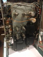
These speakers look and sound as good as you're hoping. HIGHLY efficient.
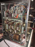
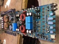
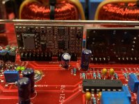
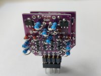
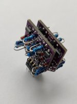
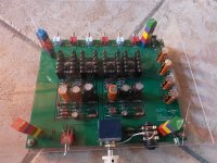
Full 8 ohm load (GPA HF diaphragms), Jeff Markwart crossovers and a pair of GPA crossovers (one GPA has a broken trace, easily jumpered). Altec + Mantaray logos. In excellent condition.
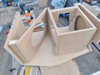
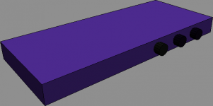
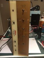
Cabinets were constructed by a master cabinet builder named Dale from St. Charles IL. Oak braced, MDF walls. Internally fully covered with a black insulation that's comparable to what airplanes use in to insulate their cockpits. Cherry veneer with Tung oil finish, it's begun to saturate with UV and looks wonderful.
Nice brass binding posts.
Includes custom made dollies with locking wheels.
Local pickup in Chicago. Not interested in separating the drivers and cabinets. These speakers are surprisingly easy to transport when you remove the woofers and load the cabinets separately. I was able to transport both cabinets in a Toyota Rav 4. (Tight but it fits).

Login to view embedded media
  • Like
Reactions: manniraj

Looking for this conector

Looking for this connector

Our Roborock S5 stopped working, and in the process of trying to fix it, I destroyed this connector. Does someone know which sort of connector this is, and where I can buy a replacement?

The outer dimension are 12*6*13mm (LWH). The pins come out in a 4x3 pattern. The counterpart is a PCB, with traces, so this is sort of a edge card connector.

many thanks!
Erik

Attachments

  • 2022-05-30 17.15.28.jpg
    2022-05-30 17.15.28.jpg
    251 KB · Views: 192
  • 2022-05-30 17.15.52.jpg
    2022-05-30 17.15.52.jpg
    357.7 KB · Views: 185

Looking for Circlotron Power Follower in the kind of Andrea Ciuffoli's Cool Follower

MONOphono preamplifier by enjoythemusic.it

Hello to everyone,
some months ago one user of this forum suggested me to look at the MONOphono preamplifier illustrated on enjoythemusic.it (click here for the article).

I decided to start building it however I do not clearly focused how to do it specifically regarding the powering.

In the attached schematic is shown that the all the circuit needs 320-350V DC so can someone provide me a solution to power it as an independent unit? Is advisable use a 5Y3 tube? If yes can someone provide a little schematic and tell me where to find a suitable power transformer (I live in Italy, so the power transformer needs to work with 220-230V AC)?

Attachments

MFB and CFB using Piratelogics Electronic

In this first post I will update all important stuff continuously for your convenience
New input interface for ACH-01 and stiffer
carbon fiber support (28 may) post 66 (better!!)
Add stiffnes post 69 (better)
Add "dust cap" stiffener... is it better?? Post 71


Background: After have been experimenting a lot with Servo subwoofers or MFB motional feedback in the 90-ties with success I went to dipole subwoofers and QUAD ESL 63 electrostatics (modified). Everything was fine until I realized that sometimes the ESL 63 playing on their own, had a magic in upper bass that can not be achieved with dynamic woofers... nope nix njet nej ikke.
8-10% distortion in a woofer does not blend well with QUAD or other electrostatics with <1% distortion in bass.

So only way out is to reduce distortion with a factor of TEN ! (Or go back to dynamic speakers..😱 naa.. )
And here is how it is done 😎
Circuit: First I am using ACH-01 accelerometer and using Piratelogic Electronics EVE 2020 circuit boards which is wery convenient, however this circuit is not designed directly to fit ACH-01 so some tweaking on some values has to be done... also using CFB is changing frequency responce and phase a lot and on top of that dipole woofer, the frequency correction and phase response will be TOTALLY different from using the EVE 2020 the "normal way"
Which is to drive voltage amplifiers with Starbass accelerometers and small woofers in small boxes. If you want to do so there is another thread by chriscam on this forum.

So be careful, the manual for using EVE 2020 will not guide you the right way for this combination... but nice and easy.
We will get it working! And if you want to make it more easy use Star bass accelerometer. They seems to work great.

The benefits with MFB CFB and Dipoles: Using motional feedback to a Dipole woofer system is double or maybe triple compared to a closed box!
First: Distortion comes with longer strokes, which you have a lot more with dipoles than any other principle.
Second: Since the dipole compensation 6dB/octave raise the low fundamental tones, those fundamental tones has corresponding harmonics which will be raised several dB! If you play a 100Hz tone, the 2nd harmonic of this tone is also lifted 6dB, and worse... the 9th harmonic 900Hz will be lifted >18dB!!
Third: The 9th harmonic 900Hz is much more disturbing and noticeable since your ears are much more sensitive in those frequencies.
Dipole woofers are hard to integrate with low distortion midbass of an electrostatic speaker!
Reed the theory papers below and in nr 3, you find the benefits of combining CFB and MFB.

Distortion reduction and measurements part 1: Post 30 shows 2-3 times lower distortion, but it will be improved!
I have reached a more than ten fold reduction in distortion or 22dB in a prototype, and here i will guide you trough the building, schematics, measurements setup and all problems that you may face during the journey, I know, I have done all mistakes there is, and will try to cover them all.

SERVO subwoofers or MFB theory:

1. http://rmsacoustics.nl/papers/whitepaperMFBtheory.pdf
2. http://rmsacoustics.nl/papers/whitepaperMFBdesign.pdf
3. https://www.rmsacoustics.nl/papers/Impulse Compensated Driver setup.pdf


Input stage: The black and white part of the schematic is the accelerometer itself and the buffer J310 68k and 820 ohm resistors, mounted on the woofer, these are SMD components glued to the cone and hard wired under a microscope... crazy idea from the beginning, and even more stupid when the J310 was fried :-(
A part of the schematic EVE 2020.0 is shown, and a table with some assumptions. With ACH-01 you should add an impedance buffer see below.. (Starbass has a buffer already built in)

Updated 220511
Accelerometer gain stage and loop mixer:
Post 4 is misleading regarding J310 FET.. see picture below.
I have seen the application note schematic for ACH 01, but was mislead by another users design.
The ACH 01 shall have a negative bias as shown on the application note, to minimize distortion.
I will do a last try with ACH-01 Otherwise I buy ClingOn from Chris, and just get it working...
Big thanks to Robert-H Munnig Schmidt at RMS acoustics for explanation!! 🏆
Rob has achieved 30dB loop gain and 45deg phase margin... is that a world record? (some people is impressed by Messi and Ronaldo....)

Stability, Phase margin, and OLTF measurements: Post 34
Stability at low frequency is achieved but at around 3kHz it looks really messy. So I am reaching out for any help, here.

Below is the input side of the accelerometer on EVE 2020 board. From here you will see that everything has to be made different with Dipoles.
ACH 01 Bad interface.JPG

How it should look like!
CaptureACH 01 interface.JPG

I did a last try with ACH-01, with stiffer carbon fiber support and new electric interface in post 66 and it works much better!

Attachments

  • Dipol sub bygge.jpg
    Dipol sub bygge.jpg
    638.9 KB · Views: 165

Floating supply amplifier (backward, transnova, qsc)

Hello,

I'm interested in floating supply power amps like Transnova Hafler, QSC, Acoustat, Dalix, and I just found these diagrams on my hard drive.

I do not know where I copied these pictures, I search for their provenance.

I searched on google, on this forum but nothing.

I like the use of op amp directly on MOSFET

Thanks
Best regard
Sébastien

Attachments

  • SVD.JPG
    SVD.JPG
    31 KB · Views: 413
  • CDL.JPG
    CDL.JPG
    119.1 KB · Views: 449
  • CVR.JPG
    CVR.JPG
    120.5 KB · Views: 418
  • FCT.JPG
    FCT.JPG
    22.1 KB · Views: 391
  • BCT.JPG
    BCT.JPG
    24.2 KB · Views: 399

Plate load triode amp, resistive load in bafle.

Hi at all.
IF i have an DHT triode amp with 3K : 8ohms output transformer.

And If i have a compression driver working since 2.5kz with 8ohms curve and also a 5 ohms resistor in series.
The plate load change with a 8 ohms driver , and the additionaly 5 ohms series resistor ?

Or this resistor does not change the load that the plate tube see since 2.5kz ?

The series resistor Influences in some way ?

Santiago

Various ways to generate NEGATIVE voltages used in Tube Amplifiers

Interested in the various ways there are whereby one can generate a negative voltage within a given tube amp design. The more legit, the better. This is asked in the context of avoiding having to install an additional AC line step down tranny. I'm also assuming "flea power", in the single digit mA or so.

I've tried a voltage doubler off an unused 6.3V heater winding. With a slight load to enable an adjustment pot, it barely gets up the -10V needed for a 6BQ5 P-P design. (Next up to bat is a voltage triple-er)

I've seen an RCA design where a capacitor connects to one side of the B+ tranny winding, followed by a resistor to ground. Then to the cathode of a diode, then cap to ground.

Other ideas?
  • Like
Reactions: prakit

Yamaha CX-800 transformer

I just got a dead CX-800 pre amp I hoped to repair. it does not turn on.
there are no fuses anywhere that I can see
120 goes into the transformer but nothing come out
input leads for the transformer shows no resistance at all, as in completely open it seems
lifted up transformer to look underneath, it is epoxy encased

outputs are
red black red for 23 gnd 23V
orange orange 14V

I am wondering why I can find no fuses at all (even on the schematic) and the big question, what can I use in place of this transformer

Parallel resistors with different brands?

I recently had my crossovers rebuilt. We changed the tweeter resistor from 2.5 ohm to 3.9 ohm to lower the output. It dropped it about 2 dB per REW test. I would like to hear it again at 2.5, but instead of removing the 3.9 (Path audio) resistor, I was going to add a 6.8 in parallel, which would drop the resistance to 2.5.

But that value is on back order from Parts Conn, could I use a different brand, say Mills MRA 12 6.8?

2 questions, is mixing brands a bad idea, and mixing values?

Thanks

Help needed with replacing transistor on Krell S-300i amp.

Hi everyone, I need some help regarding replacing one of the transistor on my krell s-300i amp.

The transistor has a marking of 1GW (very small transistor). I googled and it shows up as BC847C. I also notice that several other similar transistors have been replaced (bought the amd 2nd hand). I think they don't really last (read about high failure rate of this amp).

I am thinking if there are any alternatives for this? Something that could last longer.

Thanks for the help!!!

Rockford Punch P600x4 PS failure

I'm not positive on the identification of the PS components.

All PS fets are damaged. Looks like they are IRF1404 but I'm not totally sure. I would think IRF3205 or similar might work here in this amp? Not totally sure. 51ohm gate resistors are measuring OK but need to be replaced.

TL494 IC with several buffers. A few of them are burned and not recognizable:

Q103: ??
Q104: 2A?
D105: 5D
Q105: 1A
Q106: 1A

Is there a schematic available for this one?

https://www.crutchfield.com/S-oml7d...C_Wa2scYmqp86MxlQXGmHy6Y3RjQlgYhoCqucQAvD_BwE

Cyrus One Issue 6 - Distortion Left Channel

Hi all,

Hoping I can get some help with this old Cyrus One. The left channel sounds weak and has mild distortion. I’ve been through with a scope with a 1khz sine wave and the Voltages and wave form look great and voltage at the power transistors are identical. I’ve checked and cleaned pots and even applied the signal directly to the power amp circuit, bypassing the controls. Also there was a bias issue on this channel, I’ve reduced a resistor in the bias circuit and got 8mv. Also recapped this circuit. Any ideas guys?

cheers

600V-DC Electrolytic Capacitors for Tube Amp Applications - any Experiences ?

Such capacitors I have never seen before:
https://www.eeworldonline.com/cde-snap-in-aluminum-electrolytic-caps-handle-600-vdc/
https://www.cde.com/new-product/380lx-and-381lx/
https://eu.mouser.com/ProductDetail/KEMET/ALA7DA331EE600?qs=sGAEpiMZZMvwFf0viD3Y3a3yb5D6sPUg3Mw1Ii53gqabpUqe8jhz/A==

The usual method of connecting electrolytic capacitors in series to increase the value for VDC (when the ESR value doubles) should therefore be a thing of the past. In case of replacements of four caps all can operate in parallel mode up to 550VDC supply voltage.
Are there any experiences ?

Rockford Fosgate Prime 400-4 No Audio output.

I have actually 2 amps from the same person with the exact issue. No audio. Amp Powers up and draws proper idle current and has no shorted mosfets, or output transistors. I have had many prime mono channels amps that an inductors has came from the board. But I have seen this a few times and can not fiqure it out. I need a signal generator. For now in going to push an audio signal into the amp and try and follow the 50htz signal? It's not so easy the way the board is layed out. Just wondering if anyone has found a solution to this issue already? Or some advise

Attachments

  • 15243440040308127846128724868872.jpg
    15243440040308127846128724868872.jpg
    1 MB · Views: 348

Planet Audio RXD2400 in protect

Ive got this amp, a bit un-familiar. The driver board is epoxied. The amp attempts to power up for a brief few seconds but then falls straight into protect. All transistors are measuring OK and everything seems well enough in-order on the pcb. Any thoughts as to why it stays in protect?

Photo

Attachments

  • F5C657E2-3A51-4DAC-A478-6AF398B4CFF4.jpeg
    F5C657E2-3A51-4DAC-A478-6AF398B4CFF4.jpeg
    487.6 KB · Views: 122

Philips CDM-2/10 Laser Tuning

I am looking for step-by-step instructions, with photos, to show how to set the CDM-2/10 laser diode voltage to 50mV for correct focusing of the TOC on a CD. I have the Philips C.D.M.-2 service manual, but it is not specific on which resistor on the control board (CB) must be used. I have seen comments here that it is located in the bottom right corner of the CB. I believe this to be R3131.

I remember searching the web and finding a site where this information was contained, but have since lost that history on my browser. I have read Laserology by Lamizator.eu, and while very informative, it is not specific enough for me. Yes, it shows the pots and what they are used for, but not the resistor location on the underside of the CB.

I have also read CDM2 Revision by Bakura, and while informative, not what I am looking for. The closest I have found is the CDM 4/19 to CDM2/10 laser swap blog on audiokarma.org - and while getting close to what I need, it is still short of what I once saw on the web.

Any pointers or URLs are most welcome.
Thanks

Which speakers ???

Hey guys.

Have started a wedding band who are now looking to purchase its own PA.

We want to go with just tops for convenience and logistics ( don't want the hassle of carrying subs to every gig )

Which speakers would you recommend that can cover the whole band? And are 12 or 15's better.

Details:

7 piece band - drums, bass, guitar, keys and 3 vocalists.

Gigs - standard weddings / corporate 100 - 150 people.

Budget IS important so ideally looking for the cheapest speakers that can get the job done.

Thanks in advance

New Sleek Chip amp project

Apparently it is possible to build a Hi-Fi 'chip amp' for a very low cost. I thought it might be an interesting exercise to design one and build it later at an appropriate time.

The unit will be wall mounted on a rack similar to this one:

Initial 3D model of the case is as shown in the attached graphic.

Plan to use an external power brick and an amplifier chip that is capable of 2 Watts to 5 Watts.

Amplifier board like this one?

Attachments

  • Ames1Amp.png
    Ames1Amp.png
    5.5 KB · Views: 1,772

Old school simple project and some thoughts on opamps

I see lots of very sophisticated projects here with people doing smart stuff with Arduino and Pi and all sorts. So I feel suitably chastened in posting this but may be of some interest to someone.

Having finished my first Chipamp I was left with a Cambridge Audio A1 case and some of the internals and decided to repurpose them into a preamp to feed the Chipamp. All very simple stuff. I sourced a modest 30VA 15-0-15 toroid. I stripped out the old regulator system (just Zeners) from both the main preamp board and the input board and installed a proper linear regulator based on L78/7915. I did some rerouting on the input board to cut out the the tape loop and give myself just another line level input. Then obviously I had to rewire everything together and in doing so tried to adhere to some better routing than the original design allowed (given that it had a comparatively massive power amp board in there).

So the design (as per original) is simple. An inverting buffer on input, feeding a shunt feedback Baxandall tone circuit (so again inverting), feeding a pot and then straight to output. So this last stage is a 'passive' preamp. I use short cables and the pot is 20k (ln) so no issues there, but I will be adding a final buffer stage just for versatility to allow longer cables if wanted (may enable both buffered and non-buffered outputs).

On to opamps. So much written I know but I will keep it brief. It came with TL072 in both stages. I am a great fan of TL072 from long back and in these low or unity gain circuits I didn't see a compelling reason to change, but I had socketed the boards and so experimented a little. Tried 4558, NE5532 and AD712 (as used in more upmarket Cambridge Audio A3i). I measured all of them for noise (pretty negligible in all cases but measurable differences) and did some listening tests.

OK my ears are not good and I am not therefore a great guide on sound quality - whatever that means. In all honesty I really couldn't reliably tell them apart. Its quite useful that the tone circuit is switchable so its possible to switch one op amp out of circuit and this did reveal a very slight degradation due to the 4558 - very slight, but female vocals just didn't sound as convincing (at least not to me). For the others I couldn't have reliably told whether the tone circuit was on or off with a blind test. So on this criteria alone the 4558 drops out of contention.

On to noise. Interesting. The differences are tiny and all versions are getting close to the noise floor of my ancient Levell muV meter but here it is. The noisiest (in this circuit) was the TL072, the quietest was the AD712. The total measured difference (full volume, tone on) was only around 10muV from best to worst but given the low levels I was measuring (20-30muV) I guess this is quite a large percentage. However .... it was impossible to tell them apart in practice unless my ear was right up against the speaker. In that case I would say the TL072 noise was a bit more objectionable / noticeable as in being more popcorn like.

Then I am going to add a criteria. DC offset. No surprise here the NE5532 was worst by a country mile. So what? Well the NE5532 implementation would be unusable without some switch on delay relay / switch off mute. I say that because if ever by accident you were to switch off that preamp first (or switch it on last) with NE5532 on board there would be very loud, very unpleasant and possibly damaging loudspeaker cone excursions. I tried it without tone enabled and volume turned down and it was bad enough. The TL072 by comparison was relatively benign (but you would still want to avoid a mistake of powering down preamp with power amp on). The AD712 was just a dreamboat. I couldn't measure any DC offset and it starts up and shuts down almost silently.

Perhaps no surprises - a circuit designed with JFET opamps works better with JFET opamps. But then the performance of the AD712 in comparison with TL072 did take me aback. Received wisdom is this is an ancient 80s opamp and offers no real benefit over the TL072. And I hadn't realised the benefit of DC precision is potentially simplifying a design. It was therefore measurable better and much more practical. In fact for the audiophile approach, DC offset is so low i could easily remove at least two DC blocking capacitors per channel if I wanted to. Picture of new internals just for the hell of it.

IMG_5500.jpeg

Accuton 173-6-090 and SS Ring Radiator, 6 dB/octave, distorsions

I have 3 way DIY speakers. Midrange is Accuton 173-6-090, Scan Speak Revelator tweeter, ring radiator. The crossover is 6 dB per octave. The midrange is 120uF and 0.56 mH. The tweeter is 3.9 uF. Distortions, sibilants are heard in the area of high tones. I tried other speakers in the setup, there were no distortions or sibilants. I read about how the SS ring radiator can’t play low. I have experience with the Vifa ring radiator, which also couldn’t play low without distortion. I would like to keep the crossover 6 dB per octave, because I have expensive elements, and I also like the connection and phase correctness of such a crossover. I wonder if you know which tweeter could play with my Accuton midrange and 6 dB per octave crossover? Best from own experience with similar drivers.

Replace pinch rollers in Becker BE1480

I have a Becker BE1480 tape deck in my car and lately it has eaten two cassettes. I'm thinking that I'd need to replace the pinch rollers in this 32 yo deck which would seem to be long overdue.

When I open the deck I see a tiny plastic disc holding the pinch roller in place. My question is: can I pry/pop off the disc in order to replace the pinch roller or should I not tamper with this piece?
IMG_0043.jpg

Filament Hum Bypass

I'm sure others have come across this when selecting a power transformer. For a project I'm working on, I found a power transformer with the perfect voltage and current high voltage winding and a perfect filament current rating. Problem is the filament winding does not have a center tap. I've had the same situation before and a solution I have found that cancels background filament hum is to add bypass caps from each side of the AC filament line to chassis ground. I find ceramic caps work best for bypassing and 50V multilayer ceramic caps are small enough to fit anywhere. I ground the caps to the chassis and not directly to audio ground circuits. The 120V AC power inlet third prong ground also connects to the chassis and not directly to audio grounds. Although audio grounds do connect to the chassis, all audio grounds are wired together. Copper wire is a better conductor than a chassis giving some degree of isolation between audio ground and AC ground. I have never had a hum problem (so far 😊).

FilamentBypass.jpg

Measurement Issues With DATS

Below I Haves shared Measurements of My Driver using DATS V3
FS comes out to be 86.3 and if can be clearly see a dip of graph which the software has analyzed as fs because of impedance peak.
but can be clearly seen it can play below 86.3 hz
so my question is how to calculate fs in such case as modeling software modeled graph will be only upto 86 hz

Attachments

  • image_2022-06-16_071817534.png
    image_2022-06-16_071817534.png
    106.7 KB · Views: 120

Tuning a "Boombox"

I thought I'd re-animate this project because it my promote discussion between the factions. Summer's here. It's barbecue time so I want to create a blue-tooth boom-box. It has dual power sources AC mains and a 12v rechargeable DC battery. Somebody has to carry this so I'll limit the size to 20 litres.

At this point anybody in the car stereo business need to seriously re-think their priorities. The 12v battery needs to last all day. throwing more power at a problem can never be the answer. (Within reason) the priority has to be dB per watt. Having torn down more systems than I can recall I have an inkling how the big box manufacturers have addressed this issue.

My draft design incorporates 6 drivers (2 x 3-way speakers) in a shared 20 litre box. The woofers are 6" and the single port is tuned to 90Hz. The efficiency theory starts at the signal: do not ask the amp to waste power amplifying inefficient signals. If the amp is not amplifying signals below 70Hz (12dB per octave) then it has twice as much power to power the rest.

It's just a holiday Boom-box. It doesn't have to be perfect.

Stax ESL-F81 - need a good amp

Got a good deal on Stax ESL-F81 electrostatic speakers. They are in good working condition.

I am trying to figure out what amps would drive F81 best. I have a Class A 20W custom made ECC88/MOSFET Amp: works great with high sensitivity speakers but fails badly with Stax, McCormack DNA-1 Deluxe: drives Stax fine but is not as fluid as Aleph 3, Pass Aleph 3: works fine but clips at higher SPL and Symphonic Line RG11 that works nicely but does not bring anything special to the table. As you can see these are very demanding speakers.

An externally hosted image should be here but it was not working when we last tested it.


An externally hosted image should be here but it was not working when we last tested it.


With impedance all over the place from 2Ω to 500Ω depending on the frequency what would be an ideal amp? Please provide commercial models as well as DIY choices and general ideas.

Acoustic Blockchain - a diy guide for a versatile acoustic frame

Hi

I'd like to present a diy-instructions for versatile acoustic folding screen called Acoustic Blockchain.
Originally this blockchain was developed to be used in Finnish Hifi events by a Finnish hifi association Hifiharrastajat ry which usually means hotel rooms with minimal acoustic treatment.
It had to be light weight, no breaking parts, acoustic material is safe i.e. nothing to breath into your lungs, no injuries if it falls over, easy to transport,
easy to relocate in room where most effective, usable as a bass trap and effective against room echo/reflections and above all simple to make.
As a bonus it is 100% recyclable.

The Acoustic Blockchain is versatile and easily portable acoustic folding screen made from upholstered acoustic panels.

It has many possible uses:
  • open offices/studios
  • home acoustics (children's rooms, home office, hifi listening spaces etc.)
  • music rehearsal spaces
  • etc.

It can be used as permanent or temporary solution as it can easily be folded away (and even put under the bed) when not
needed releasing usable room space for other activities.

This gives you an option to have acoustic treatment in front of windows, doors etc. during critical listening. Also it is easy to find the most effective place for acoustic treatment as you can easily relocate it during listening/making room acoustic measurements.

Direct link to the guide at issuu.com: Acoustic Blockchain
The attached Acoustic_Blockchain_improvements.pdf contains few ideas on how to possibly improve the original design.

Material used is polyester wool with density of 22kg/m3.

Attachments

Looking for equivalent TL783 / LM783

Hi guys.
I'm looking for an equivalent or replacement part for this IC: TL783C or LM783C.
I have an AMEK-TAC series 350 power supply and this part is mounted in the 48V phantom section. I fact, it is the only IC or transistor present in this 48V circuit. Here is the circuit diagram.
Can anyone help me?
Thanks in advance.

Attachments

  • IMG_3195.JPG
    IMG_3195.JPG
    226.9 KB · Views: 694

18sound 18LW1400 sealed for HT

Hi,

I can get this subwoofer locally at a very good price (don't recommend any other model as in my country we don't have many available) thus I would like to know how well can the 18sound 18LW1400 perform for subwoofer duty, considering this:

-. I have a very small room, maybe 8 or 9 square meters.
-. Use will be for HT
-. Listening levels will be between 85db and 90db (maybe even less)
-. Have DSP capability
-. The idea is to build 4x subwoofers like this

So, taking advantage of the huge area of this SW, the great sensitivity and power handling and kind of poor XMAX, I though:

-. Use 2 drivers per box, connected in parallel (4ohm)
-. sealed box around 50 liters (for the 2 drivers)
-. 500w amp
-. Apply some Linkwitz Transform + HP around 10hz + (-)12db gain across al the spectrum (I don't need 120db@100hz)

With all that, I do have some good performance according to WinISD. I do hit XMAX at around 200W but I am already above 100db@20hz! Also, I would assume that 8x 18" will pressurize my room at a whole other level.

I understand that according to WinISD I will need a TON of power (above 2kW) but if I consider the huge room gain I might get in my room then I can use a higher fp in the LT and reduce the power needed to get similar performance, or maybe get a bigger sealed box of around 80-90 liters.

So, are these assumptions correct? I uploaded some pictures comparing this simulated driver (in red) vs a dual SBAcoustics 10" SW26DBAC76-3-DV in a small sealed box (in blue)


Cheers

Attachments

  • excursion.JPG
    excursion.JPG
    113.7 KB · Views: 150
  • spl.JPG
    spl.JPG
    103.3 KB · Views: 140

Where to start help please

I am wandering here from the Chip Amp pages having just completed an Lm3886 project. I am now keen to explore the world of Class D. So far my only experience is Fiio A1 desktop speaker amp. Pulled it out of the case and it seems to be based on TFA9815T with an OPA2134 op amp front end (nice touch!). This little critter sounds pretty good but I am keen to build a Class D amp for myself. I dont want to populate the boards so really am looking for advice on what sort of completed boards to source with a view to putting it all together. Maybe with a linear power supply (as I feel comfortable making one of those)?. Thanks

SB15MFC or SB17MFC for 2-way?

I have a pair of SB26STCN tweeters looking for a mid-bass and crossover. I'm assuming the SB26STCN could stand in for similar SB26 tweeters with a slight mod as necessary. I don't have the tools to design a crossover so would be dependent on an existing crossover, so I have attached the various choices. I'm open to using either the SB15MFC or SB17MFC depending on your opinions on each driver and your opinions on the crossovers in the existing designs that use them.
If necessary I could use a NRX part or one of the other SB26 tweeters, but the MFC version would be a little easier. Smallish room, lower listening levels, classical, opera and jazz, SE 2a3 tube amp which works fine with smaller 2-way bookshelf speakers. Don't need too much power or deep bass.

So hoping for some recommendations here. My all means include any other SB15/SB17 designs I haven't mentioned.

SB15MFC-08 midwoofer SB26ADC-04 tweeter. Sutantoroy
https://www.diyaudio.com/community/...tandmount-speaker-project.339276/#post5826477
https://www.diyaudio.com/community/threads/2-way-sb15mfc-08-sb26stc-04.315253/#post-6838731

SB15MFC -4 & SB21SDC tweeters, Xover 3KHz. "The Lockdown"
https://www.diyaudio.com/community/threads/sb15mfc-2-way-the-lockdown.374155/#post-6709256

Not sure how well SB15NRX designs would work with SB15MFC
https://techtalk.parts-express.com/...st-diy-build-sb15nrx30-8-sb26stcn-4-pic-heavy
http://www.audioexcite.com/?page_id=6373 Kensho 2

SB17MFC35-8 midwoofer SB26STAC tweeter. Bagsby The Tributes
https://meniscusaudio.com/wp-content/uploads/2015/11/Tributes-Write-Up.pdf

SB17MFC35-8 midwoofer SB26ADC-C000-4 tweeter Troels Gravesen 61-MFC
http://www.troelsgravesen.dk/SBAcoustics-61-MFC.htm

SB17MFC35-4 midwoofer SB29RDCN tweeter
https://www.diyaudio.com/community/...me-choose-a-crossover-frequency.266766/page-2

Again not sure how well SB17NRX designs would work with SB17MFC
SB17NRXC35-8 woofer and SB26STC-C000-4 tweeter.
https://www.diyaudio.com/community/threads/2-way-project-improvement.379112/
SB17NRXC35-8 woofer and SB26ADC-C000-4 tweeter. Troels Gravesen
http://www.troelsgravesen.dk/SBAcoustics-61-NRXC.htm
SB17NRXC35-8 and SB25STC-C000-4. Ralph's Chameleon
http://zaphaudio.com/DLR/

10M35S CCS help

buongiorno,

this is my first attempt to use a ccs. it is for the driver section (EC86) of a single ended power amp with the 45.

I am unable to obtain a stable operating point as it vary with the variation of the volume control...

  • volume control from zero to the first quarter: operating conditions are those highlighted in RED (8mA 1.8V 12V)
  • in the transition from the red to the green zone the amplifier emits a bump in the speakers
  • volume control in the central part of regulation: the values suddenly change to those highlighted in GREEN (6.3mA 1.1V and at the anode vary from 40v up to 80v and then down to 40V)
  • in the transition from the green to the blue zone the amplifier emits another bump in the speakers
  • volume control in the last quarter to full: the values return almost the same (highlighted in BLUE) to those of the first quarter of regulation.

strange thing is that the power amp sounds anyway, even with 12v plate voltage ...
what could be wrong ?

grazie!

Attachments

  • ccs.png
    ccs.png
    18.3 KB · Views: 302

WTB: Playmaster 132

Apologies for cross posting (I think I may have used the wrong forum when I posted my original message).

------------------------------------------

I’m new to the forum and would like to ask if anyone has an old Playmaster 132 that they’d be willing to sell. The design of the amplifier was originally outlined in Electronics Australia in 1971 (June, pp. 44-51; July, pp. 36-41; August, pp. 38-39 and p. 150). I don’t mind the condition of the amplifier (e.g., working, not working, in bits, parts missing).

The reason for my request is that I was passionate about electronics in my teens when the articles for the Playmaster 132 were first published. I couldn’t buy the parts at the time because I didn’t have the money. I’ve just recently retired from a career unrelated to electronics and I’d like to return to the passion of my youth. I’ve worked on a number of radios and amplifiers in the last year, but I yearn for the opportunity to purchase and work on a Playmaster 132.

If anyone can help me or give me some ideas about how best to proceed, I’d be most grateful. I’ve spent a considerable amount of time over the last six to nine months scouring various websites in Australia without success (e.g., eBay Australia).


Thanks,

Old Phoenix

WTB: Playmaster 132

I’m new to the forum and would like to ask if anyone has an old Playmaster 132 that they’d be willing to sell. The design of the amplifier was originally outlined in Electronics Australia in 1971 (June, pp. 44-51; July, pp. 36-41; August, pp. 38-39 and p. 150). I don’t mind the condition of the amplifier (e.g., working, not working, in bits, parts missing).

The reason for my request is that I was passionate about electronics in my teens when the articles for the Playmaster 132 were first published. I couldn’t buy the parts at the time because I didn’t have the money. I’ve just recently retired from a career unrelated to electronics and I’d like to return to the passion of my youth. I’ve worked on a number of radios and amplifiers in the last year, but I yearn for the opportunity to purchase and work on a Playmaster 132.

If anyone can help me or give me some ideas about how best to proceed, I’d be most grateful. I’ve spent a considerable amount of time over the last six to nine months scouring various websites in Australia without success (e.g., eBay Australia).


Thanks,

Old Phoenix

Twin Driver Full-Range: Fane 12-250TC

Loved the result when I built the Fane Sovereign 12-250TC plans posted by Scottmoose here:

https://www.diyaudio.com/forums/full-range/246746-12-range-fane-12-250tc-39.html

A friend sold me his pair of 12-250TCs for cheap and I couldn't resists. Now I have a quad of 12-250TC drivers.

Does anyone have any ideas how to create a twin driver box for two Fane 12-250TCs? Or an OB plan with two drivers per side?

Help finding a budget mono amplifier

Hello all.
I am posting after a long time . First i am a complete noob on this amplifier thing.
2nd sorry if i did/about to do any mistake out of my lack of knowledge. I intend to buy this particular tda 7293 board because it is cheap and convenient.
100W Digital Power Amplifier Board TDA7293 / 7294 High Power Dual 12-32V Single Channel Audio Amplifier Module for DIY Speaker
a.aliexpress.com

3.62US $ 18% OFF|100W Digital Power Amplifier Board TDA7293 / 7294 High Power Dual 12 32V Single Channel Audio Amplifier Module for DIY Speaker|Operational Amplifier Chips| - AliExpress

Smarter Shopping, Better Living! Aliexpress.com
a.aliexpress.com
a.aliexpress.com
7293 amp1-1200x1200.jpg


My subwoofer is a 75w RMS old Philips one.
Can i drive it optimally with it?
I intend to run this amp with a 35-0-35 VAC EI transformer (yep i am mr. Cheap 😛 ). One of the top most priorities is to keep it economical .

Other options:
1. Tda8954th btl mode
2. STK 4048

PLZ help

Any info on Philmore SA-2000 tube amplifier

I got a Philmore sa-2000 and I was wondering if anybody has any information on it or if you have the schematics. There is almost no information on it on the web.

I opened it up and it has 2 x 12ax7 and 4 x 6BM8 in a push-pull setup. All tubes turn on but there is a loud buzz that comes out from the speakers, even at minimum volume. The buz increases slightly at max volume but very little. The heaters are AC. When feeding music through it it is heavily distorded in the low end.

I’m wondering if it’s worth trying to fix or restore it. Does anybody know anything about the quality of this amp? Any schematic out there? I can’t imagine having some unique or proprietary circuit.

Thanks

Attachments

  • 8E38D347-D43A-42E3-8F8E-A2DAE18CC33C.jpeg
    8E38D347-D43A-42E3-8F8E-A2DAE18CC33C.jpeg
    598.1 KB · Views: 300
  • EE196731-9A2D-4DAD-B05D-727C1D352887.jpeg
    EE196731-9A2D-4DAD-B05D-727C1D352887.jpeg
    304.2 KB · Views: 226
  • D27B431E-8357-44E9-A528-B664F67ADD41.jpeg
    D27B431E-8357-44E9-A528-B664F67ADD41.jpeg
    447.9 KB · Views: 284

Fitting class d for studio monitor repair

Hey peeps,

i have a rokit 8 g2 monitor where something with the amp is broken. I want to replace all the inner parts with a class d and a dsp, as I simply want to start playing around with speakers, amps and dsps. So not interested in fixing the original pcb.

The monitor has 2 drivers:
  • 1x Tweeter TWTK00012 with 4ohm and supposedly handles 20W
  • 1x Woofer WOFK80156 with 4ohm and supposedly handles 70W

(Source: http://www.dancetech.com/item.cfm?threadid=4483&lang=0)


My idea on how to make them work again is to have following audio chain:

Code:
Audio Input -> t.racks DSP 4x4 [as crossover/gain/eq] --- > woofer signal  --> class d 70w --> woofer
                                                      \-- > tweeter signal --> class d 20w --> tweeter


Now is the big question what kind of class d to get, i like the idea of getting china class d and play around with them.

For the 20w i found this class d from adafruit: https://www.berrybase.de/adafruit-stereo-20w-class-d-audio-verst-228-rker-max9744
But it looks crazily tiny and not sure if it really can handle 20w.

For the 70w woofer I found TPA3116D2 based 100W class d modules. It has a variable resistor on it with which i could probably turn down the volume
until i reach ~70W.

What do you think? Should that work? Any ideas? Problems i'm overseeing?


Thanks,
obsoleszenz

Western Electric 14a?

I have always liked the 14a was thinking using as a top for a 15”

Can anyone give me reasons for or against using this design? Has anyone built the 14a?

I don’t have a pair of WE555s and don’t want clone$. Can anyone suggest a CD driver that can be crossed over at 250-300Hz? Also under 250$ would be helpful.

I have heard tell that the angled connector to the we555 on the original design is critical, can anyone comment on this?

I have rough external dimensions and interior shape but not exact dimensions. Does anyone know where I can find these? A 1930 patent shows some things.

Thanks for the help!

Lumber for horn housing

I'm making a housing for a composite horn. The 10" driver will be in a small (barely bigger than the driver) enclosure, and I'm building a larger box to protect the horn and allow stacking and a pile mount (it's for events not home audio).


It will deal with a lot of SPL, but I was hoping/guessing that since none of the enclosure will serve as a resonant chamber, and I'm not going below 200hz With it, I don't need to buy specialized wood (void free Baltic birch vs Home Depot sanded ply).
that's my thought, but we all know what they say about assuming thing!

oh, and speaking of NOT resonating, any recommendations on what to use to dampen the box around the horn? Ideally something light.

Carbon CB2200.1 or similar

What's up guys, I'm seeking some information on the output mosfets for this amp particularly the insertion arrangement.
It was started by another person but they pulled the outputs and I think they got it mixed up, so far I see the amps uses 640s and 9640s (the "s" is for plurality).
It's 5 pieces per rail on one side (10 pieces for complete rail plus/minus), what fets do I insert on the positive rail and what fets for the minus rail?

Attachments

  • IMG_9288.jpg
    IMG_9288.jpg
    897.5 KB · Views: 185

Electrolytics change

Hello, I have to change the 4 big electrolytics in the PS of my Threshold Sa/3.9e.

What brand do you suggest for best sound/reliability?

In the forum 'Thresholdlovers' I find written:
go from Mallory (31000 microfarads / 75v) to United Chemicon Ucc (33000 microfarads / 85v) or RIFA (33000 microfarads / 100v) or CORNELL DUBILIER (xxx / xxx); add 4 Elna (470 microfarads / 100v); bypass with 4 Vishays (0.47 microfarads / 630v in parallel); change resistances from 10% to 1%; bias adjustment to 1.6.
What do you think?
Thank you.

Thanks

Cyrus Two - Restore at 120V or convert to 240V?

I am in the UK and have just purchased an early Cyrus 2 amplifier (Issue 04). The reason I bought it is because 1) I love restoring Cyrus One and Two amplifiers and 2) I've never seen a 120V model.

Seeing as I have a spare transformer from my 240V donor unit, I was wondering if anyone her could give me some advice on whether, in terms of resale value, it would be worth converting the amplifier to 240V or restoring and selling on the amplifier at its original 120V specification?

I would probably be putting the unit up for sale on eBay once it is ready so I'm hoping that, if it remains at 120V, it would pick up some interest from buyers in 120V lands due to the inherent rarity of 120V models.

On the other hand at 240V, these amplifiers restored still have a strong resale value in the UK and in Europe.

Any advice gratefully received!

Do ported speakers really act like an IB above the port resonance frequency?

Do ported speakers really act like an IB above the port resonance frequency? I’ve seen this quoted, but is it true? Has it been researched and is there any evidence? I’m wondering about this for the following reasons: an IB enclosure volume has an effect on the bass units performance (f3, transient response, etc.) At the port resonance frequency the hole in the enclosure will be “plugged” by the oscillating air in the port, but what if the speaker was reproducing a solo piccolo piece? Would there be enough low frequencies in order to set the port into resonance? If not, would the speaker essentially be an IB with a massive leakage?

For Sale EH KT 120 Quad NIB

Hello
Due to ongoing health issues I’m selling my matched quad of NIB TUNG SOL KT 120 tubes
This quad has sat unused since purchase from parts connection and are ready for a new owner to unlock their potential.
I am now asking $380 usd including shipping to CONUS.
The tubes will be double boxed and insured and I’m sure the buyer will be delighted.
I’m away from home until 5/3 and at that time I will post pics of these beauties.

Located in Oakley, Ca. pick them up, save $20 and you get a complementary door prize which won’t suck.Edited post as I had listed EH as the brand where these are T Sol
Thanks for looking today.

Tube with in a tube speaker

Hi guys,
Just bought a pair of markaudio CHR 70 drivers. I was planning on making concrete enclosures for them, but I then thought how could I do it easier save making all the wooden moulds. Then it struck me how about a 1m 160mm pipe inside a 200mm pipe, then fill the void between them with concrete with the top and bottom being capped off.
Any advice on whether to do a MLTL or ported, I was looking at the Mark 8 design a ported 1m long floorstander with an internal size of 112 x 160, hence my choice of a 160mm pipe, should give about the same internal volume.
Any advice would be appreciated.

Neil

The X-FoBooster is a transformer-like in-line booster

Here is another project inspired by Danny: it is based on the same principles as the BoosterPhone, low supply requirements, rail-to-rail output on a low impedance, in this case 600 ohm and decent audio quality without too much complications.
It is designed to match older sources, delivering 150~200mV to modern equipments requiring 700mV or more. It thus mimics a passive step-up transformer, but without the impedance penalty: a 1:4 step-up transformer increases the impedance by a factor of 16, which can be problematic. Instead, the output impedance is much lower than the input.
Although the X-FoBooster requires a supply, unlike a copper & iron one, it has no power switch and lasts forever on a single charge: the supply current is comprised between 55 and 85µA.
First, the simplest version optimized for 3.7V:

XfoB37g.png


This is the graphical version, based on the real prototype. The sim uses the native transistor types of the LTspice.

Now the 5V version:

XfoB50g.png


Here is the non-inverting version: a bit more complex, but it has a self-centering quiescent output bias, and a THD of 0.03% against 0.1% (at 0dBm/600ohm, actually measured)

XfoNI37g.png


XfoNI50g.png


The values shown as comments are the ones used in the physical circuit. The others are suitable for the sim.
All the transistors are also 2SA1015/2SC1815, except the lower output transistor Q6, which is a BC547C.

The output is referenced to the + supply, and it requires a DC link to work properly. If it used on a cap-coupled input, it is necessary to include a dummy load of 1 to 2K.

I didn't build the various versions as complete projects, because I have no use for them (for the moment), but I breadboarded them, and the measurements are based on the breadboarded circuits.
The 3.7V version can use the same battery management as the Boosterphone, and it will last even longer

Attachments

New project, Mazda BT50 single cab install

Got a little different project going some car audio.
I've obtained a new ute (little mini truck for my American friends) its a 2008 single cab flat tray Mazda BT50.
Just started working on it today making the sub box and planning out the door speakers... man I hate using fiberglass. Being such a small cab there is no real room for the sub in a conventional shaped box so Im making the box as a center console between the seats and it'll go up the rear cab wall to the window, I can only manage approx 30ltrs(1 Cf) of volume which is ok for most 10~12" car subs but Im lacking in width(230mm between the seats) so Im going to run 2x 8".
Parts list so far
2X Dayton UM8-22's
Door's will contain a Dayton RS225-4 for midbass duties, some Philips GTM 4" for midrange I've had them for years never used, and Im thinking of using some tweeters I've had for years also Jaycar response 19mm or the ones supplied with the GTM's.
Also have a Dayton 408 DSP to allow me plenty of adjustments and I'll be reusing an Alpine MRX-V70 5ch amp from my old ute, the UM8's will be wired for 2ohm on the sub channel and the RS225's on two channels and the GTM/tweeters on the remaining two channels, if there's not enough watts for the RS225's I will bridge the four channels into two and buy a small 2ch amp for the GTM/tweeters it'll all depend on how its measures when I get it up and running.
The Midrange and tweeters will need a passive xover made or I could use the ones supplied with the Philips GTM's... I'll have to do some testing/measuring may even end up buying some small coaxials or another set of 4'' splits(Focals would be nice).
Anyways that's where I'm at, I'll post up some progress pic's in a few days.

Two way with ribbon?

Hi all,

This is a bit more of a thought at the moment than anything.

I have a pair of alpair 12pw woofers lying around which were originally going to be used in a WaW set-up, but for a few reasons I don't think that'll be happening anymore.

I am curious about true ribbon tweeters and I'd like to see what they can do. I am concerned with using them in a two-way as I understand they don't usually reach too low.

The alpair 12pw can reach high with no issues, but I'm concerned about directivity if crossing about 3k+

I was wondering what everyone's opinion would be on this? The 12pw measures about 13cm from edge to edge, measuring from the edge of the surround. It's quite a flat profile cone, but there is no directivity data unfortunately.

My budget is only around £100 per tweeter so I was originally considering the fountek neo cd3.0 as I understand it's quite a popular unit

So in summary, I would like some opinions on the following:

1) Would crossing at 3-4khz cause noticable issues with directivity?
2) Are there any ribbons that can reach lower than typical?
3) I am also concerned about time alignment of the drivers and I don't know if I'd be able to do this passively. Any input on this is welcome
4) Any honest opinions welcome as this would be my first ever speaker/xover design. I don't mind some trial and error, as long as the driver selection is a good on paper and it has the potential to be a good speaker

Thanks

Any chance to modify a Yamaha XH150 (high impedance amp) to low impedance amp?

Hi,

I picked up a Yamaha XH150 which you guessed it is an high impedance amplifier, and I'm looking to see if you can mod it to an low impedance amplifier?

(I saw in another thread it was possible on a different 100v amp link)

I've attached the service manual that also has schematics.

Any help will be greatly appreciated?

Thank you!

Attachments

Best topology for no-feedback ClassAB buffer ?

I'm looking to make a simple impedance buffer, something that has a high Zin and a low Zout - whilst avoiding the high idle power dissipation of a Class A design. I don't want any feedback (except for degeneration perhaps).

Power requirements are low (e.g. <10W) so cross-over distortion at low power is perhaps the limiting factor.

Candidates include double EF, Krill O/P, Sziklai buffered EF, Diamond buffer.

What would you recommend and why ?
Projects by fanatics, for fanatics
Get answers and advice for everyone wanting to learn the art of audio.
Join the Community
507,669
Members
7,883,457
Messages

Filter

Forum Statistics

Threads
405,990
Messages
7,883,457
Members
507,669
Latest member
dukerd74