Apparently it is possible to build a Hi-Fi 'chip amp' for a very low cost. I thought it might be an interesting exercise to design one and build it later at an appropriate time.
The unit will be wall mounted on a rack similar to this one:
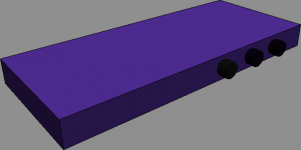
Initial 3D model of the case is as shown in the attached graphic.
Plan to use an external power brick and an amplifier chip that is capable of 2 Watts to 5 Watts.
Amplifier board like this one?
The unit will be wall mounted on a rack similar to this one:
Initial 3D model of the case is as shown in the attached graphic.
Plan to use an external power brick and an amplifier chip that is capable of 2 Watts to 5 Watts.
Amplifier board like this one?
Attachments
Last edited:
My question is can I build a decent-sounding low power amp with these parts. For me, even a PC speaker amp sounds decent when connected to the right speakers, I listen at low volumes.
Estimated Cost: (in USD)
Enclosure (metal and wood DIY) : 5.00
Power adapter : 12.00
Amplifier Board : 8.00
Total = : 25.00
Estimated Cost: (in USD)
Enclosure (metal and wood DIY) : 5.00
Power adapter : 12.00
Amplifier Board : 8.00
Total = : 25.00
download the datasheet and read it completely.
Ask here about what you don't understand.
Then decide if that chip is what you require.
After you have built the amp on the bench and tested it to ensure it is working properly, then work out how small it can be folded up to fit inside a box.
After that you can order up a box that fits the final amp assembly.
DON'T buy a box and then try to fit everything inside to find that the amp does not work !
Choice of amplifier board ?
Choices for the amplifier board.
Most probably I will purchase off eBay and get it posted over here. Or I can buy it locally:
Uses PAM 8403
Which is discussed here: http://www.diyaudio.com/forums/chip...8403-matching-speaker-beginner-questions.html
The LM 3886 gets good reveiws in this site:
Choices for the amplifier board.
Most probably I will purchase off eBay and get it posted over here. Or I can buy it locally:
Uses PAM 8403
Which is discussed here: http://www.diyaudio.com/forums/chip...8403-matching-speaker-beginner-questions.html
The LM 3886 gets good reveiws in this site:
Last edited:
download the datasheet and read it completely.
Thanks, Andrew. Will do that, but my previous attempt to build an amplifier ended up badly with a huge hum from the output. I connected an AC power adapter : maybe this was the problem, however what sort of power adapter specs should I look for to run an amplifier board out of? 1- 2watts is okay for a start: the low-cost mini amps can run off an adapter so it must be a case of finding the right adapter.
I think these boards are pretty small, I am thinkin of building a case the size of a small DVD player, that is 20 cm by 40 cm or so.
It's because there are usually problems that need a solution that I never recommend that you assemble inside a casing/chassis.
Get it working spread out along the kitchen worktop, or along your electronics work bench.
This makes access for measuring and/or modification and/or re-wiring much easier.
Get it working spread out along the kitchen worktop, or along your electronics work bench.
This makes access for measuring and/or modification and/or re-wiring much easier.
I understand. If I had assembled my first chip amp outside the casing without soldering, maybe in 1995, I would be very far ahead of where I am now.
Dr Casette has a testing setup here.
Apparently some problem with the circuit board caused oscillations. Who would have imagined.
Dr Casette has a testing setup here.
Apparently some problem with the circuit board caused oscillations. Who would have imagined.
Project motivation
The reason for starting with the case of the amplifier is simply that many of the projects I see do not have enclosures that look as professional as the commercial amplifiers do, for the most part. In my opinion, the lower powered amplifiers are more suited to my use of listening at SPL of 70 dB at 1 metre, not more than that.
I have listened to the following systems with music on CD:
Sony STR-333 with Sony SS_G333ES
Sony CFD-6 portable CD casette Stereo Realistic 40-1011 woofers
TEA 2025 based powered PC speakers with Realistic 40-1011 woofers
As far as I know all the chip based amplifiers, from the 2 x 1 Watt amps to the 25 W per channel amplifiers sound good enough for my listening. After all the STR-333 is specified at 25W/channel. Much depends on the speakers, which I will be putting together myself using the above drivers. The attraction of building an ampifier for less than $20 and having it sound as good as I have heard, as well as looking great is an opportunity I simpy cannot pass up now.
All that's left now is to choose the correct chip. In terms of cabability, I would like to know which of these chip amps have been tested for accurate reproduction of a varying signal or music, for example with a null test, or some comparison of input signal pattern to out put signal pattern at different volume (gain) settings. I don't think the spec sheets will give this or will they?
The spec sheet for TEA2025 gives the THD at 1KHZ only. If I keep the output power below 0.6 W (how to measure this?) it should sound alright. Can we hear distortion?
The LM3886 looks very impressive in the spec sheet. Low distortion. But it costs.
The PAM 8403 is better than the 2025, it seems.
The LM3886 looks very impressive in the spec sheet. Low distortion. But it costs.
The PAM 8403 is better than the 2025, it seems.
Board Search - Mini PAM8403 2*3W D Class Digital Amplifier Board
Looking at amplifier boards for my amplifier project. This one seems interesting.
Uses the PAM 8403
You Tube video of testing of the board is here (in Russian, though) . Judging from the sound over my pc headphones it has an open, clear sound with acceptable or should I say perfectly satsifactory bass. At one point the person testing the board pushes it into distortion, not sure what the conditions are.
video
Last edited:
I used to listen on 1 and 2 watt amps, but found I'd hit clipping too often if I wanted it a bit louder or with dynamic material. Wattage of your amp should be based on speaker sensitivity, listening room and position. Since the amp is to be mains powered, I think you'd be better off going with something above 5 watts unless you just need something for back ground music.
My listening environment is a little unusual since I frequently have to be able to hear conversation also at the time of listening - I can't listen at loud levels since I will not be able to hear anything anybody says.
I have found that 75 dB/W/m is sufficiently loud for my purposes. The main concern is that the speakers should be at the same level as my ears - this is requiring the use of wall mounted speakers, and the lack of bass at low levels which the PC speaker amp I am testing seems to boost bass at low levels somehow.
The speakers in my room setup are the Radio Shack 40-111 with the sensitivity of 92 +/- 2 dB/1W/1m which is quite good
The PAM8403 is discussed in this thread. Also, from listening to this video it sounds quite clear with sufficient bass.
The module is on eBay and it is cheap:
The module is on eBay and it is cheap:
Task update:
1. Choose amplifier board - in progress.
Internet searches. Stores are closed for holidays
2. Design and build amplifier case - in progress
Preliminary design done, cardboard mock up to follow, then aluminium enclosure will be built
3. Choosing power supply - not started
will be done with board.
1. Choose amplifier board - in progress.
Internet searches. Stores are closed for holidays
2. Design and build amplifier case - in progress
Preliminary design done, cardboard mock up to follow, then aluminium enclosure will be built
3. Choosing power supply - not started
will be done with board.
Last edited:
Found a TDA2822M in a transistor radio I recently purchased for the equivalent of about $5. Maybe I could use this and build a receiver? It is a stereo chip. according to the data sheet, in this case used for mono for a single speaker. Testing the output using headphones showed a good frequency response spread, with the distortion being from the radio reception, I would think.
I've never been more confused as to WTF is the purpose here... Make cheap crap in a box for not listening to music?
If you only need a couple watts use a buffer that can put out 1a per channel, for the best possible sound. However choose one that clips well because you'll always get clipping.
If you only need a couple watts use a buffer that can put out 1a per channel, for the best possible sound. However choose one that clips well because you'll always get clipping.
He tells you in that section.the buffer stage, which (for the non-inverting configuration) can have an extraordinarily high input impedance, and a low output impedance.
How really is this buffer circuit supposed to work?
Same article, full quote. I do not quite understand what he is saying:
Is he saying that an op amp will normally have its output connected to very low, say for example an 8 ohm impedance speaker, but the op amp will not be able to deliver a large current to the speaker. The op amp will clip once the limits are reached.
How does the buffer circuit prevent this? Does the buffer circuit use a second op amp- shown in the diagram - to ensure the correct current output to the speakers from the current output of the first op amp? Presumable this could be done by connecting the appropriate resistors to the buffer op amp as shown?
Same article, full quote. I do not quite understand what he is saying:
Inverting and Non-Inverting Buffers
A very common opamp application is the buffer stage, which (for the non-inverting configuration) can have an extraordinarily high input impedance, and a low output impedance. As with all opamp circuits, the output impedance may be very low (typically < 10 ohms), but the output current capability will not allow the circuit to drive such an impedance at more than the 20mA or so that is typical of most opamps. This would limit the output voltage (before clipping) to a maximum of +/-160mV, or about 113mV RMS into 8 ohms. Distortion will be unacceptably high, and the end result is not worthy of further consideration.
Is he saying that an op amp will normally have its output connected to very low, say for example an 8 ohm impedance speaker, but the op amp will not be able to deliver a large current to the speaker. The op amp will clip once the limits are reached.
How does the buffer circuit prevent this? Does the buffer circuit use a second op amp- shown in the diagram - to ensure the correct current output to the speakers from the current output of the first op amp? Presumable this could be done by connecting the appropriate resistors to the buffer op amp as shown?
I just purchased this mini amplifier circuit board.
More detail is found here on the ebay listing.
The input connections are listed as R, L and T. I take it the T is for the common (negative) terminals of the input? Does it matter?
More detail is found here on the ebay listing.
The input connections are listed as R, L and T. I take it the T is for the common (negative) terminals of the input? Does it matter?
- Home
- Amplifiers
- Chip Amps
- New Sleek Chip amp project