Full Bridge rectifier with no voltage increase?

This is obviously an ignorant question, but I can’t seem to find the answer.

I’ve made a few simple full bridge rectifiers from four single diodes/2-pin and having the voltage multiply by about 1.4x. These are mostly being used in single rail regulated power supplies.

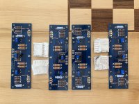
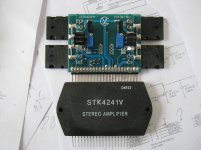
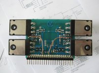
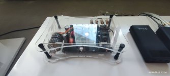
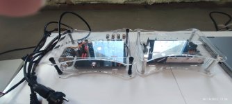
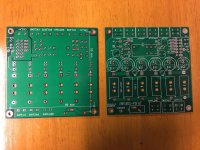
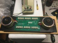
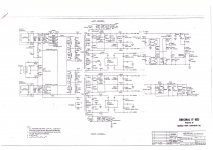
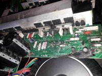
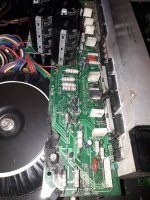
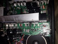
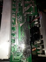
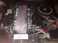
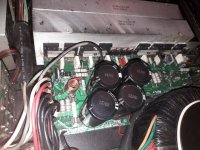
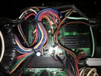
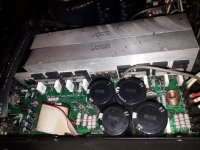
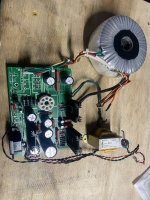
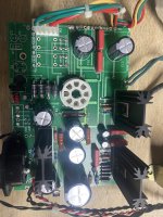
Here I’ve grabbed a PCB for a common cathode dual anode full bridge rectifier to feed a single rail power supply and am getting no voltage increase at all, just the forward voltage drop. Not expected, and won’t give me the needed voltage from this transformer!

Is this how it’s supposed to work without any voltage increase across the full bridge rectifier?

rectifier pcb common cathode 1.jpg

Bluetooth

Hey,
I want to add Bluetooth connectivity to a dac that I’m building. Really just looking for a Bluetooth receiver/ transmitter that I can incorporate within my build. The dac is based on an AD 1862N that has been graciously offerd by a member , Miro 1360. It looks like a great implementation and I will initially be using a i2s over usb board from jlsounds to access files from my Mac mini (2012). The addition of Bluetooth will allow a somewhat easier way to explore more music. I will probably set the inputs up on a switch to go between each source, which is another issue I need to settle. Anyway, suggestions please for something you’ve tried and some details
Thanks

Troubleshooting Lafayette LA-224B

I have just finished a re-cap of my Lafayette LA-224B and have been going through the power-on procedure. A schematic is available below. Here is what I did:

- Replaced the can capacitors (only these -- the others were changed before and the amp worked fine afterwards)
- Re-wired the output stage. I removed the headphone jack, headphone switch, and phase switch from the circuit because I never used them. I realized when I was re-capping that there was a lot of "back and forth" trips through the chassis of the amp for the output signal to get just from the OPTs to the speakers, so I eliminated that and wired the OPTs to the impedence switch directly, and then the switch to the speakers. So on the schematic it basically now looks like the left channel for both channels, with the "PHO/SP" switch replaced with a wire to the speaker terminal.
- The feedback lines were also replaced with a shielded cable, grounded at the output tap end.

I'm running through a dim-bulb tester with a 100W bulb in.

When I run with only the rectifier, and only the pre-amp tubes, the amplifier comes up and is stable at ~350V (w/ preamp tubes), which sounds about right. The bulb stays off.

However, as soon as I add any power tube, in any position and any combination, the amp will come up to ~300V, but then start dropping quickly down to about ~175V before I turn it off. The bulb also starts off a bit brighter than with just the preamp tubes, gets dimmer, and then gets brighter and brighter.

I'm thinking that I introduced a short somewhere, but I'm having a tricky time finding it. It's also strange that the behaviour starts only once the power tubes start conducting. If I had introduced a short in the cans themselves, I would expect this to show up almost immediately.

So, any pointers on where I can look next? I've checked a couple times that the can capacitors are hooked up correctly, and unless there's some magic in the output stage that I accidentally removed I think I got that right.

Attachments

For Sale 2 sets of built F5 boards - $225 OBO

Sold - 2 sets of built F5 boards.

All parts purchased from the diyAudio Store.
2 pairs of F5 boards
2x F5 parts kits
Matched Octet of Toshiba 2SK170/2SJ74 Idss 8-11mA

Boards have been built but never tested. Never mounted, MOSFETs are still in their foil.

Asking $225 OBO (incl. shipping to USA/Canada)/$200 for pickup in the Denver area.

Sold As-Is. Paypal only.

Attachments

  • IMG_0114.JPG
    IMG_0114.JPG
    823.6 KB · Views: 185

Need some help with LTSpice modeling for a new amp build I am working on

Hello all.

I am in the process of trying to design my own tube amplifier. It's actually more of a redesign of an existing amplifier schematic. Having never designed my own amp before a friend suggested it might be smart to run the design through an LTSpice model to make sure I haven't overlooked something. Good advice. Well, having never worked with LTSpice before I have run into a few issues that I can't seem to solve on my own.

Background on the amp:
  • 6sn7/6sl7 preamp and phase inverter stages
  • was push/pull el34 output tube based...would like to move to push/pull KT120/KT150/KT170
  • would like it biased class a1
  • adding an ac bootstrapped follower to the inverter for more gain so I can drive the new output tubes

Issues:
- LTSpice didn't have library files for the 6sn7, 6sl7 or the KT120/KT150/KT170 tubes. This was partially solved when a friend referred me to the following thread here.

https://www.diyaudio.com/community/threads/vacuum-tube-spice-models.243950/

I downloaded the library and inserted the files into my schematic (I think I did that right). Ayumi did not have the KT120/150/170 in the library to I inserted the KT88 as a placeholder until I find a suitable library file for the biggerl KT tubes.
  • I can't find a library file for the LM334 current source
  • I can't find an output transformer file and lack the skills to create my own
  • I can't model the negative feedback because it comes from the 16 ohm tap on the transformer.......which I haven't been able to figure out
  • Lastly but most importantly when I run the simulation it comes back with a singular matrix error around the LM334 node, which I can't figure out

I would like to reiterate that I am no expert amp designer (first one) and I am not an expert LTSpice ( first time using it) so any help offered would be appreciated very much. Here is the schematic.

Myamp.jpg

Happy Papa’s Day!

Here in the US we are celebrating Father’s Day.

It wasn’t too much of a coincidence that I was on DIYAudio this AM and yet again was reading and receiving advice and guidance from people like Nelson “Papa” Pass, Zen Mod and others?

I think not.

Here’s to all the Father figures and mentors that guide and help us to learn and grow so we can experience those wonderful things we aspired to when we were children! (Even if we’re still children on the inside 😁)

Happy Father’s Day!!!
  • Like
Reactions: JMFahey

Technics SL-PS900

Hello friends

I have three units of this beautiful CD player. It is a top model of Technics range: separate audio and digital transformers, with separate sources, first level mechanics and self-adjusting pick-up ... only 2 adjustments are necessary when replacing the laser pick-up. Magnetic displacement, similar to the KSS-151A.
Solid and good functioning.

Now I want to go a little further with these units, and I was wondering what would be the most recommended mods, I assume a new clock, and a replacement of capacitors ... but what more mods, would be recommended?

Attachments

  • IMG-20190624-WA0001.jpg
    IMG-20190624-WA0001.jpg
    901.8 KB · Views: 1,132

Bypass Caps in Tube Headphone Amp

Hello everyone, I have been a little confused about the coupling caps with the .68UF bypass caps. I thought I'd find the coupling caps between the tube stages but it seems to be on the output, on the way to the phono jack. Am I looking at it wrong? I have tried some substitutions for the bypass caps and found that going somewhere closer to 1UF seems to avoid passing some of the harsher treble but retains the high end sparkle. I am hoping for some schooling in this regard. My dear old dad would have been a wealth of knowledge here and kept me on track; he was a great EE with a passion for old radio stuff, but he is long gone, and I miss the readily available expertise. He had me up to speed, 20 years ago, but I have just recently gotten back into electronics and have forgotten a lot. Hoping for some insight. Thanks!


Little dot Mk II scematic.jpg

Output Relays

Sh1t Happenz.
My 250 watter blew a channel this weekend . . .and took the bass units out on one of my B&W 703’s. As it went out, there were sparks and noises coming out of the of the amp and then a smell like burnt varnish from the speaker.
I was and still am mightily pissed off.
At first I thought it has the Vbe multiplier that had opened up, but after removing the module and checking the components, it seems an MJ21194, MJE15033 and an MJE15032 blew short. The pre-drivers, VAS and all the small signal components were ok, although the driver emitter resistor was badly burnt (this is a 27 Ohm that connects the two driver transistor emitters together – both drivers were short, so this resistor had 140V across it before it too open circuited). The 0.22 Ohm 7W emitter ballast resistors on the output devices made it though – even on the 21194 device that blew s/c. It looks like the output device failed short, put about 75V across the speaker, causing the bass drivers to fail.
Then I wondered why the MCU based protection controller did not kick in and open the output relays as soon as it detected an output DC condition. I took a look at the relays. Well, one set of relay contacts was ‘stuck’ (i.e. welded) in the closed position and the cover was smoked over in the vicinity of the contacts. So, it looks like the other two relays opened correctly (or dropped out when the power was pulled).
In my wisdom, and against everything I was always told about paralleling relay contacts, I had put 3 sets of relays in parallel (Tyco RP3 16A 250 VAC devices) in the interests of low output resistance. The MCU probably tried to do its job, so relays 1 and 3 opened up as the fault protection kicked in, but the last relay to open up was #2. I don’t know at this stage whether or not the failed contact actually did open correctly, only to succumb to subsequent arcing, or whether it simply stuck because it was well outside the DC load capability.
If you look at the relay spec, it shows the DC load breaking curve as displayed below. At 75V, the DC load breaking capability of the relay is about 1.1A, or about 10% of the probable current that flowed during the failure event. This was probably enough to cause the contacts to stick together and blow the speakers.
The lesson to be learned here is that relay DC handling specs really do need to be adhered to. So, I will replace this relay and fix the module up, along with my speakers, but for all new power amp designs, I will go with a different appproach. Many people recommend using an auto relay, but I checked out the DC load switching capability and its not clear that they would reliably switch on a fault condition. I did some research and the Panasonic EP(AEP) series look like they may do the trick - the 10A PCB mount version.

Now, I have to work out why the damn output stage failed in the first place.

Attachments

  • Relay Data1.png
    Relay Data1.png
    26.9 KB · Views: 5,564

When STK4241V burn...

First, sorry for my bad english.
One friend of mine bring to me Sharp SX-8000H(GY) for repairing. Left channel not working. Relatively quickly I discovered why. STK is burn out. Аlso it is not original.I buy a new one from e-store, it was described as a original SANIO but it was exactly the same, fake.
I try to repair the burned one. I removed all parts and replaced them with new ones. Complete waste of time and money.
A little :scratch1: and finally :idea:
I must build a new module, based on the internal schematic of STK and fully compatible electrical and mechanical.
Here is the result. Currently running the latest checks. Working steadily and I think that is a good alternative.

Attachments

  • stk 004.jpg
    stk 004.jpg
    817.9 KB · Views: 675
  • stk 008.jpg
    stk 008.jpg
    984.8 KB · Views: 680
  • stk 014.jpg
    stk 014.jpg
    802.9 KB · Views: 716
  • stk 016.jpg
    stk 016.jpg
    831.6 KB · Views: 1,063
  • stk 017.jpg
    stk 017.jpg
    558.7 KB · Views: 623
  • stk4241vgv2.pdf
    stk4241vgv2.pdf
    257.9 KB · Views: 313

Conversion of Hiraga's "Le Monstre" to a Circlotron

Hallo together

the original circuit is mirror symmetric between pos and neg halves (so called "true complementary push pull") but in real life I missed the symmetric behavior - see foto about clipping
"Photograph 6: Stability at Clipping - 1kHz into 8ohms " by URL
http://diyaudioprojects.com/Solid/Jean-Hiraga-Le-Monstre/ (scoll down, last photo)
If you compare the rising edge of lower half to the falling edge of upper half, you see the different.
Additional the 300 KHz Sine Waves are more like a sawtooth, what is bad omen (no low IM distortion at high frequencies)
How I can I convert Hiraga's "Le Monstre" to a CSPP version (cross shunted push pull)? By the output stages allone I haven't problem (there are some examples on this forum), but include the input stage I don't find solutions.
Thank you very much for your advices

Adding SPDIF input to Adcom GCD-575

I have several Adcom GCD-575 CD players where the laser has died and rather than dump them I thought it might make a decent DAC project. Has anyone added an external SPDIF input into the model? I’m not looking to keep the cd transport as part of this conversion.

Components in this unit look pretty decent and I remember the TDA1591A sounding nice when it was working. If I can get this unit to function as a stand alone DAC, upgrading the opamps and power supply would follow.

Thanks in advance for any help on this

Hornresp advice please - Hilding Horn Line Array (foam core / Faital 3FE25 / 4FE35)

Hi all,

Can I get a sanity check on this please:

Inspiration
I found this: Hilding Horn , whilst bumbling around the old threads, and thought it looked a viable candidate for a foam core build.
Maybe a curvy build if I can work out Hornresp!

Outline:
I like the idea of an 8 (or 4) driver (fullrange) array as this can be reproduced, and stacked easily; if the prototype works out well.


Driver:
Faital 3FE and 4FE are available in UK, for not too much, so I have earmarked these as the driver of choice - I know there are better for cheaper etc... I'm leaning towards the 3" to keep the C-C spacing down and either the 8 or 16 ohm variants.

Material:
@xrk971 use of foam core has inspired me to give it a go too (especially when you consider the cost of plywood)
Also, if the horn doesn't workout I can easily/cheaply make a new enclosure to try.

Questions:

Is a horn loaded (or ported) line array a bad idea?

Can anyone advise what type of horn the Hilding is? I guess it is, initially, back loaded but what does it become after the folds/split?

Any recommended guides for a newbie Hornresp user?


Many thanks.

Cambridge Audio Tream Magic 6: Main Standby Swich does not turn off the device

I can not anymore turn off the Cambridge Stream Magic 6. Pushing the button on the front panel to change the unit to standby mode has no effect. The switch feel a little softer than usual, might be worn out mechanically. The unit does not react on any command by the remote control in any way. Could be problem of very old overstocked spare batteries, I have to try brand new ones. I see myself able to replace the main switch, where can this be bought? Any comments or ideas how to fix this one? Thx for any help,

S.M.S.L P1 PSU 120v to 230v conversion

Hi all, I have a S.M.S.L P1 Linear Power Supply that I bought and used in the US and is for 120v/60Hz. I have now moved to the UK with 230v/50Hz power and want to attempt a DIY conversion.

The Talema datasheet says (it may not be a Talema transformer but appears to be configured the same):
  • For 230 volt operation, connect primaries in series by connecting pins 5 & 4 together and apply 230 volts across pins 6 & 3 [It appears only pins 3 and 6 have 230v?]
  • For 115 volt operation, connect primaries in parallel by connecting pins 6 & 4 together and pins 5 & 3 together, apply 115 volts across pins 6 & 5 [From these conenctions, it appears 3, 4, 5, and 6 all have 115?]
  • To parallel the secondaries, connect pins 14 to 12 and 13 to 11 take the output across pins 14 & 13
  • To place the secondaries in series, connect pins 13 to 12 and take the output across pins 14 & 11
The back of the PCB confirms this (first photo below).

Now it appears that I have to break the two connections between 3-5 and 4-6. Then, connect 4-5. But my question is, what do I do with 3 and 6, and do I have to make any other adjustments?

(I also note that this has two LM317 regulators, which I wasn't able to find photos of anywhere else. I'd like to eventually replace those with drop in replacement LM3045 one day!)

20220612_161852.jpg


20220611_123312.jpg

20220611_123752.jpg

RPI +Volumio-can it access an iTunes library on disk?

Hi folks

I have a slightly flakey from age Mac Mini (2009) that I am using with Puremusic as a music source to a USB DAC. I really don’t need a new dedicated Mac mini computer for this application. I want to try getting away with a RPI4 with Volumio or perhaps some other player software. I would like to add streaming to the mix as well. I currently have Amazon Prime music as a starting point. Is it possible for the RPI to access files from the mini? I have about 1000cd’s ripped in AIFF on a pair of FireWire 800 drives. One drive is for time machine backup. The drives also have a USB interface. I don’t want to start over ripping discs. The overall plan is to have a NAS to serve all our data needs in the house. We need to replace all our old hardware at this point. If we can replace a mini with an RPI then that would help the bottom line a bit.

Thank You
Brian

Please review my 3-way crossover

I want to build a 3-way ported speakers with two woofers and I would like to know your opinion on my crossover.

Woofers: 2x Dayton DC300-8 (in enclosure with 240 liters (8.5 cubic ft) just for woofers, bassreflex tuned to 25 Hz)
Midrange: Dayton RS150-4
Tweeter: Dayton RST28F-4

I was trying to have impedance curve as close as possible to 4 ohm (not less than 3.6 ohm) not to damage the amplifier as it can handle minimum 3.2 ohm. That is the reason of R2 rezistor in woofer section otherwise the impedance drops to 3.1 ohm. Also zobels and notch filter were used.
I was checking inverting polarity of mid speaker - there is quite good "deep" but I do not know if it is ok because the deep is a bit weird.
Impedance curves show peaks at frequencies about 300 Hz and 1900 Hz, so I suppose those are cutting frequencies, right? I was not counting them just trying to have frequency curve as flat as possible with phase of all speakers as close as possible.
Woofer section has a bit higher SPL as for a "baffle step loss".
I do not understand why tweeter takes so much power. Should not be that a woofer?

I will be very grateful for any comment or review of my crossover.
FRD and ZMA files are attached.

Thank you in advance.

Attachments

  • crossover.jpg
    crossover.jpg
    61.3 KB · Views: 569
  • frequency.jpg
    frequency.jpg
    141.9 KB · Views: 506
  • frequency - inverted mid.jpg
    frequency - inverted mid.jpg
    150.1 KB · Views: 475
  • impedance.jpg
    impedance.jpg
    125.6 KB · Views: 449
  • impedance peaks.jpg
    impedance peaks.jpg
    143.3 KB · Views: 455
  • power.jpg
    power.jpg
    134 KB · Views: 207
  • frd & zma.zip
    frd & zma.zip
    21 KB · Views: 88

Virtual woofer on 4 fullranges

The idea of using multiple small fullranges instead of a single midwoofer has been increasingly haunting me recently. What problems and potential advantages do you see for a practical design case of four 3” drivers tightly colocated ? Some of them come in square shape with a side length of 80mm. So colocating them next to each other would give a virtual square midwoofer of 160mm x 160mm size, so from the outer dimensions roughly equivalent to a single 6” driver. I would think of connecting them in paralel in pairs and amplify separately. If my assumptions are right that would mean a 12dB efficiency uplift compared to a single driver FR. Then using some low-pass FR DSP shaping I could preserve the bass efficiency and then above 200Hz adjust it to the target upper range efficiency. I can see quite a few advantages of such design but have never seen anything similar. Maybe there are good reasons also in terms in acoustic quality why it is not practised ?
And a related question - what would be a good driver for this application. In my research I have initially selected the attached Peerless but when studied its parameters I got doubts. I do not have too much experience in TS parameters and different driver design philosophies so I would greatly appreciate some enlightement here. What are the key differences between high Qts drivers like this Peerless and less stretched ones like e.g. the attached TangBand that is also in the game ? What is the intended application of both ? It surprises me that TangBand has a few times smaller linear excursion than Peerless - is it again some consequence of different compromises, design philosophy and/or intended application ? It seems Peerless might not be intended for a closed box that I am considering here – the Q enclosure is then forced to be high and the internal volume large ?

Pawel

Attachments

Audio controller

Hi,

I don’t know wether this is the right place to be asking this question.

But would anyone be able to point me in the direction of sourcing a controller that could play different sounds when different buttons are pressed?

Im making a little play thing for my young one and I want to put buttons on it that play a different sound with every button.

Thanks

Transistor replacement and thermal paste for NAD 7020

I am attempting a repair of my 1980s NAD 7020 receiver, the first version with one large board containing most of the circuitry. For those that don't know, the 7020 is essentially the 3020 integrated amplifier with a tuner added, and like the 3020, has a preamplifier section that can be connected to an external power amplifier while bypassing the internal power amplifier. I have determined that the preamp and all the inputs and controls work well, but the power amplifier has a dead left output. Inspection of the circuit board showed that there is a burned transistor and associated resistors (please see photos). The burned transistor is Q609, a BD139 unit.

I have obtained replacement parts, including BD139G transistors, resistors to replace the damaged units, and all new electrolytic capacitors. I removed the burned transistor from the board for further inspection but since I have never performed this kind of repair before I think I need more information before proceeding further.

The BD139 units are attached to the heat sink with sheet metal screws that go through the body of the transistors and have white thermal compound (which has hardened with age) between them and the heat sink. There is also a thin wafer (Mica?) between the transistors and heat sink which has thermal compound on both sides. The wafer on the removed transistor appears to be undamaged. Both the original and the replacement transistors have a metal plate in the center of the surrounding plastic on the side that attaches to the heat sink. This metal plate has full continuity to the center leg of the transistor (no resistance). The heat sink has full continuity to chassis and signal ground. I am confused as to the type of thermal compound I should use on the replacement unit (electrically conductive or not?) and don't know whether I should replace the wafer given that it is undamaged and I don't know what material to use.

I would appreciate some guidance before I proceed with my repairs. What type of thermal compound should I use (electrically conductive or not), should I replace the wafer, and should I replace the compound and wafer on the transistor in the other channel, given that the compound has hardened? I have performed circuit repairs before this, have experience with soldering and unsoldering, and possess the schematic and service manual for the 7020, so I am confident to move forward if I can get my questions answered. Thanks to all who reply.
IMG_0045.JPG
IMG_0049 (3).JPG

Looking for Tube amp ideas

I'm looking for some ideas for a suitable stereo tube amp to build that will ideally deliver around 15 Watts of power per channel. I have some (loose) constraints:

  1. I'd like to base it around a massive Paeco mains transformer I have (photo in attachments): this has secondaries of 289V 200mA, 207V 125mA, and four 6.3V heater secondaries for a combined total of 15 Amps heater current.
  2. I'd like to use 6080 tubes in the final stage, as I have about ten of them looking for a purpose.
I considered an OTL, but the large plate currents are a challenge: for a stereo amp with six 6080 tubes, I think I'd need a +/- 120VDC supply delivering 1Amp on each rail. The Paeco transformer would be fine for the heater supplies for the 6080s (2A per tube), but there's no way to get the plate supply currents from it. Hence my search for a different idea.

I realize that it's perhaps a bit odd to start with the transformer!

Attachments

  • 20220607_225830979_iOS.jpg
    20220607_225830979_iOS.jpg
    278.4 KB · Views: 188

General questions: Amplifier PSSR, caps and noise floor

Hi,

Sorry, some basic questions. Looking for feedback mainly on peoples subjective experiences with regards to power supplies for power amplifiers.

1. For an amplifier with high PSRR, which is dead silent with just an all C’s power supply, does choice of cap still affect sound (e.g Panasonic vs Mundorf caps)?

2. For the same amplifier, with a high PSRR, which is completely silent on tweeters on sensitive speakers is there any merit going for ‘fancier’ power supplies. E.g CLC, CLCLCC etc? I ask because I have found double regulation to be beneficial elsewhere, for example DACs, DDC’s - e.g taking ripple down to nanovolt levels.

3. For an amplifier with moderate, to low, PSRR, let’s say the noise floor is -100dB with a CLC power supply. If I moved to CLCLCC with bypass caps and so forth will the noise floor drop even further, say down to -110dB. How do you know when the power supply design has reached the limit? How would you know if self generated noise of the amplifier itself means there no further merit because a fancier power supply cannot overcome it?

Thanks for helping me work through these points!

Gavin

Open Baffle

Hello,

I'm looking to build a pair of open baffles using the Lii Audio F-15 full range speakers.

Actually I've already built a quick version with some plywood I had laying around. They're (HWD) 84x70x2,2 cm and not super sturdy. I'll attach some photoes ASAP.

I'm quite surprised and pleased with the sound and therefore want to optimise both their looks and their sound. I'm particularly looking fuller midrange.


So a couple of questions:


- What will a bigger baffle give me? Particularly if I make it wider? Is there a limit to how wide (and tall) it should be?

- How important is the rigidity of the baffle? 2 cm is not very thick plywood, and my baffles don't fell super stiff. What will a thick baffle yield in terms of sound improvements?

- Is there an easy-to-use program where I can calculate baffle dimensions etc.?

- Also, is it OK to use thick MDF or HDF as baffle even on bigger baffles?

Hope you can help!


Malm

ASL AQ1003DT schematic or manual?

AQ1003DT Manual or schematic
Hi guys,
I accidentally posted this elsewhere as a "reply"
... so I'm now instead posting it as a new thread.. ok?

I'm wondering if any of you guys might have a copy of the schematic for this amp or maybe a manual for the Antique Sound Lab AQ1003DT integrated amp.
I'm buying (my first entry into the audiophile world) a nice, mint, used one and there is no manual with it.
So I would like to see the schematic, of course, anyway.
Maybe someone can direct me to a site for a users manual too?
If you have the schematic print at least and are willing to help me out by emailing me a copy, I'd very much appreciate it.
I'm at:
pbpix AT optonline DOT net

Also... I know it sounds very noobie-dumb ....but I would like to know if anyone can recommend a pair of reasonably-priced (maybe book-shelf) speakers below $400 that I can hook up to it to begin to appreciate what I have here.

Thank you,
Peter

Is 92/93dbW/m achievable with a bookshelf?

I have two couple of speakers, JBL4311b I bought as a teen and JBL L220 I have since 2-3 years, suspensions renewed and crossover updated, former 91db latter 90db efficiency, driving them with 45W KT88 and the L220 sound amazing, I switched to solid state but 25W Class A are on the edge and also the dimensions of the JBL are way too important for my listening room.

I am chasing a friend who owns Sonus Faber Electa Amator II who wants to upgrade but he is too much of a thinking back and the curiosity to know about DIY kicked in, I know you can't expect a bookshelf to sound like my L220 (amazing speakers for their age!) and even my friend coupled the SF with a subwoofer but what about efficiency, is there anything which can reach 92-93dbW/m on a bookshelf size?

Grazie

Seeking input regarding a power transformer testing setup

I recently purchased a power transformer which purportedly came from a British tube, er, valve guitar amplifier from the 1960s. I can find no documentation for it so I will need to test it to sort out the windings.

I understand it is not advisable to just plug it into the mains and probe the solder lugs so I’m cobbling together a much safer test setup.

Here’s what I have on hand:

1) Hammond 369AX power transformer. This was originally ordered for use with a tube phono preamp, hence the filament supply. Seeing as it’s 125-0-125V (40VA), I’m assuming I can use it as an isolation transformer.

2) Older model Calrad 45-739 variac. I can’t find a manual for it but it looks good and feels good under adjustment. It’s fused (5A) and rated at 500VA. I don’t have the three prong adapter as seen in the picture but have one around somewhere I can use as seen in the link.

I’m going to set the variac at 1/10 the mains voltage.

The testing arrangement will be mains —> isolation transformer primary::secondary —> variac —> DUT

so anyway, am I good to go? Any suggestions? Should I fuse the isolation transformer as well?

thanks in advance.

Attachments

  • 369AX.pdf
    369AX.pdf
    271.1 KB · Views: 105
  • 5A787D58-5838-4A10-BC4A-CB9DE884932B.jpeg
    5A787D58-5838-4A10-BC4A-CB9DE884932B.jpeg
    435.5 KB · Views: 96

Unusual question about Naim amps lack of output inductor

Hi there

People may have seen news of recent devastating flooding along Australia’s east coast.

I am helping family and friends try to get some music happening to cheer them up and one home has multiple speakers running from the autoformer shown in the photo.

Electronics were flooded and destroyed. I have loaners but the only amp that will easily fit is a Naim Nait or NAC90 which as standard for Naim need long Naim cables because they have no output inductor.

My question is will the autoformer provide this missing inductance?

Thanks, sp

Attachments

  • 1A25679E-DE8F-4095-A2DB-4076CF177640.jpeg
    1A25679E-DE8F-4095-A2DB-4076CF177640.jpeg
    440.6 KB · Views: 337

Bucket bottom for 10" cone driver box

Not sure how sturdy the sealed container for my 10" driver (feeding compressed into the throat of a horn) needs to be, but it calls for a VERY low volume container so I thought the bottom of a home depot bucket might serve better than an 5"x11"x11" square plywood box.

Not sure if it would flex too much (mainly the bottom/round part). Maybe reenforce the bottom?

P3A capacitor choice/changes over years in original design

Here is the current link to Rod Elliot's page and the P3A amplifier.
You can note that in the input he uses a 100pF capacitor to ground.
https://sound-au.com/project3a.htm

What is interesting is that years ago when I downloaded the schematic the value of that same capacitor was 220pF. I still have that older schematic which has a value of 220pF.
Why such change?

I myself am currently thinking of what capacitors to put in this amp because I tested it with a square wave and got unpleasant output results, with a square input and a purely resistive output dummy load I got sawtooth looking output in my scope.
Some capacitor values were off so I will change them to spec, namely 100pF, what should I do with the input to ground cap? Follow the latest advice and use 100pF?

I am also thinking of using polypropylene caps , before I had ceramic.

Any advice from members is welcomed, thank you.

Mark Levinson protection circuit - Need help

Hello everyone
I have an annoying issue with the protection circuit of a Mark Levinson 23.5 that I would like to solve. I need your help.

Basically, when the amp is well warmed up and I turn it off I cannot turn it on because the protection relay of the power switch is activated and I have to wait ~30-60 seconds. It doesn't happen all the times, about 80% of the times. The problem is not present when the amp is cold. The previous owner says the problem only recently showed up, so that's not how the amp is supposed to work.

I'm attaching the schematics of the protection circuit: basically it is located on two different boards linked with two cables. The first board hosts the sensors and sends a signal through the cable to the second board, the signal should activate the relay when something is wrong in the amp (temperature, DC offset etc.).
By disconnecting the cables that link the two boards the problem is still present, so the problem is not some malfunctioning in the amp that triggers the sensor (luckily). There must be a problem in the relay circuit in the second board that activates the relay coil only when turning off/turning on, and only when the amp is warmed up. I don't know whether the relay switches on during turn off or turn on unfortunately.

The second board is very difficult to disassemble because of the MANY fast-on connectors, so I didn't take it apart yet. But visually everything looks fine and I tested in circuit with a multimeter all the resistors and diodes and they test good.

The part of the schematic we are interested in is in the right upper corner. P340 carries the +83V unregulated line directly connected to an old 36000 uF big can capacitor. P332 and P333 are the two cables that connect the sensors and associated circuit from the two channel boards to the optocouplers; disconnecting both cables doesn't eliminate the problem.

Any clue about what can be wrong and how to diagnose/fix it?


Thanks anyone in advance!

Attachments

  • Scan_20200409_081559.jpg
    Scan_20200409_081559.jpg
    513.9 KB · Views: 1,247

Direct Drive amplifier for DIY ribbon?

I'm interested in building a DIY ribbon loudspeaker in my free time over Christmas break and would like to drive it directly. Following the resolution of some meetings with faculty in the engineering department, I might be able to gain access to the Universities Laser Vibrometer and Anechoic chamber for measurements (and comparison with the RAAL 140-15D)😀

I do not wish to use a transformer, as I believe it may contribute excessive distortion. As a result, I will need a special amplifier to drive the ribbon. The impedance of the ribbon will be almost purely resistive, but very, very, very low. Most of my knowledge in the field of loudspeakers is related to acoustics and the physics of transducers...I haven't yet been able to extend it to amplifier design.

My primary goal for the project is reproducing a Dirac Pulse/Square Wave, so impulse response will be weighted with the highest significance.

Are there any designs available? Can anyone recommend any texts?

How difficult would it be to build a direct drive 10 watt amplifier with negligible distortion (linear and non-linear distortion <20khz)?

Thanks,
Thadman

Why Is This L20.5 Amplifier Whistling With A Dummy Load?

So last year I bought a pair of L20.5 amplifiers. On first power up one was fine and the other burned up the outputs without a signal.

I finally got around to fixing it today and while testing it with a dummy load (no speaker) I noticed it was whistling. I have never heard an amplifier whistle or hum before. (I have heard transformers or SMPS make noise but not a solid state amplifier board.) With the exact same setup the following do not hum or whistle: L20 V7, uPC1342V, MX50X2, MX50SE and YJ L28. Note that the whistle noise is not coming from the dummy load. It is definitely coming from the amplifier board.


I am not yet sure which component is whistling but I think it might be coming from near the 10 Ohm resistor and the yellow film/safety capacitor. (See the red arrows in the attached picture.) I can't image why any of the components on this board should hum or whistle.


I have also attached the result from the THD test which indicates that the amplifier is basically working properly. Offset is 5 mV. Bias is a little low but I can adjust that later.


Does anyone have any idea why the L20.5 might whistle during a 1kHz THD test? (At 64W.)


Could it be in any way related to why several L20.5 owners have reported sudden failure (blown outputs and more)?

Attachments

  • Whistling L20p5 Amplifier.png
    Whistling L20p5 Amplifier.png
    598.1 KB · Views: 327
  • 16Vrms Fuse 15A.png
    16Vrms Fuse 15A.png
    137 KB · Views: 349

L20SE help to add overcurrent protection ?

Hi. I wonder if knowledge and support is out there to help with building in some active protection into the L20 SE design?

I have added relay protection which would protect the speakers but I’d also like to protect the amplifier from the speakers (quad electrostatics).
These speakers will put an effective near short across the speaker outputs of the connected amp I believe. Quad amps such as 306/606/405 take this in their stride and this is what I’d like to build into these little wonders as I’m loving the sound and low noise level.
Maybe LJM can help or others with some ideas to detect and reduce the current to the output transistors in overcurrent conditions fast enough to protect the outputs.

Canton Displacement Control (DC)

Hi folks,

I like to start a discussion about what Canton calls "Displacement Control".
As far as I understand, this is basically just a passive high pass filter suppressing infra-sonic material.
The alleged benefit is clearer bass since the driver has less excursion in the infra-sonic range.
Canton's passive Reference speakers come with this feature for example.

I wonder how exactly the DC feature is implemented.
My guess is that this is just a first order high pass filter, i.e. a series capacitor.
According to some basic simulation in LT Spice, ~3300uF in series with the bass drivers could do the job.

Some decades ago, removing the output capacitor from solid state amplifiers was a major leap so adding back the (DC blocking) capacitor seems somewhat retrogressive.
On the other hand side, a loudspeaker would be more robust with such a DC capacitor added since DC from the amplifier can no longer destroy the bass drivers coil.

Looking at a (unfortunately low resolution) photo of the crossover, I can see an array of six capacitors on one of the PCBs.
Could be that those are for the DC feature?

Does anybody know something about the Canton implementation (since I'm only guessing)?
Do other manufacturers also use infra-sonic filters?
Does it make any sense in you opinion?
What are possible draw-backs?

Attachments

  • Canton_Reference_K_Frequenzweiche.jpg
    Canton_Reference_K_Frequenzweiche.jpg
    17.2 KB · Views: 196

Correlation Between Published Data and Real World Performance (Drivers)

As a brief introduction, I find myself circling the rabbit hole of DIY speaker building. I'm on the precipice, and I am trying to get an understanding of appropriate expectations.

On one hand I am aware that mass produced speakers typically use fairly inexpensive drivers and components, but they manage to end up with a final package that can be quite good and inexpensive. On the other hand, a single driver with a really flat response curve may cost as much or more than a pair of these mass produced speakers.

This leads me to wonder if the driver with a "jagged" response curve is likely to behave better in an ideal enclosure? Or is the data sheet pretty accurate to what you are going to get before adding crossover/ dsp? (I don't mean jagged in the break up region; I mean cases where the driver's best range is jaggy.)

My current system is active studio monitors. They aren't super expensive, but they perform pretty well with a pretty flat in room response. But I'm not sure how easy or hard it will be to recreate that type of response. It seems to me the options are to fix every "jaggy" with a crossover or DSP (I expect to use DSP), or to get an expensive driver that doesn't need much correction. Or is it the third option where the driver's real world response is better than the data sheet would indicate?

I hope that is enough to start a conversation. I know speaker building is more complicated than meets the eye, so I guess this is my way of asking for some real world experience that can help me get beyond the basics of speaker building. If you know what you want to end up with, how do you get there without buying all the drivers and testing them?

Record Fairs.

For individuasl selling anything audio these days is one big hassle and fraught with rip-offs both for sellers and buyers. The insistence on many platforms using Paypal as a payment method has only negatives.

Firstly, Paypal currency transfers are outrageous, the rates used are worse than tourist rates. Currency transfer companies, there are many and they are all regulated charge a little over the 'inter bank rate'. I have used Transferwise, now called Wise is now a listed bank and you can hold different currencies which means that buyers can pay in their own currencies. There are other features of this bank which are excellent but not relevant to this thread.

For someone like me that has an extensive LP collection to sell soon just take a look at the marketplace forum on discogs to see the nightmares you can get involved in both as a seller and as a buyer. Then there is a worldwide effort by tax authorities across the world to screw as much as they can out of anything imported into a country. What really hacks me off is they put an import tax on the shipping/insurance as well.

Record Fairs - at the moment in Europe there are not many and not often so I am going to my local commune (I live in France) to see how much it will cost to hire a big hall that is near to me. It has loads of free parking, is near a rail station that links to a big city, Toulouse and another Rodez and has excellent major road connections.

There are so many positives for Record Fairs:

(1) you cannot get ripped-off with total lying descriptions be it an LP/CD/DVD/tape - you see exactly what you are buying. As well as media, valves, resistors,caps, all kinds of components can be sold and bought.

(2) postage/shipping costs - to buy a single LP via post in France is a minimum of €6.50 and there is no risk of damage. If you visit a R/F by car and come with 3 other friends, if you only buy 4 LPs/CDs each then you save around €100 that buys an awful lot of fuel and you know exactly what you have bought.

Maybe you and your friends have media, LPs/CDs you want to sell, so you can both buy and sell - no risk of a scammer using Paypal procedures to rip you off. No packaging to buy or protocols to go through (IOSS). Selling platforms, discogs,ebay etc. hve charges which are around 20-30%.

I want to try to get amateurs interested if I can before the professional sellers. I intend to visit radio stations to get DJs on board - publicity is everything and of course social media. If the first is successful then this will generate interest in regular R/Fs.

As well as buying and selling there is the real chance to make friends and contacts. The i/net is great but personal contact is the best.
  • Like
Reactions: lcsaszar

A Mid-range passive radiator . . . is this a real thing?

I've just destroyed a Samsung surround sound speaker. I was surprised by what I found inside. The bottom unit appears to be a passive radiator but its surface area is only the half the size over the main drivers. The speaker has a passive high-pass filter at about 1Khz.

Is this a gimmick or is there any method to this madness?

Attachments

  • samsung-s.jpg
    samsung-s.jpg
    5.6 KB · Views: 155

What Schade Feedback Leaves Behind

This simple amp, a 2A3 driven by half of a 12AX7 is connected with Schade FB & compared to if it were
connected with the same degree of NFB from OPT secondary to the AX7 cathode. And without FB at all.
With no FB the Damping Factor (DF) is 1,7. With 9.4 db Schade FB connected the DF improves to 3.4.
But with the full loop FB of 9.8 db the DF becomes 11.74.
Schade NFB does not correct for OPT winding resistance.
The winding resistances used here are similar to that of a Hammond 125DSE.

Attachments

  • 2A3 12AX7 FB Pair No FB.JPG
    2A3 12AX7 FB Pair No FB.JPG
    38.2 KB · Views: 472
  • 2A3 12AX7 9.4 db Schade FB.JPG
    2A3 12AX7 9.4 db Schade FB.JPG
    39.5 KB · Views: 476
  • 2A3 12AX7 FB Pair 9.8 db NFB.JPG
    2A3 12AX7 FB Pair 9.8 db NFB.JPG
    38.3 KB · Views: 498

Most underrated audio designer by the audiophile community: Pat Quilter

Well...I have proof!
First hand:
Login to view embedded media 2CV puts out 29HP but it feels like 30!
Second hand:
Yesterday I got for free a broken QSC RMX1850 HD, one of the earliest QSC to introduce a switching class B for the upper part of a class H amplifier.
Apart from being a very heavy unit employing 4 rectifier bridges the only thing that was completely fried was the protection circuitry on one channel..I mean everything starting with R4...and not a single power transistor, not one!
I'm thinking to remove all the protections , scrap the class B upper part of the amplifier , remove 8 power transistors, rewiring everything for half rail replace the heatsinks with the vertical flow ones, screw some holes into the case for air convection and I'll have the most reliable 120 watts/8ohm amplifier with that 10 kg transformer...thinking of faster transistors, rectifiers and op-amps too , 0.44 ohms instead of 0.22 ohms emitter resistors as in the older versions and maybe the kenwood l-01a driver stage rewiring 😉

Attachments

  • Screenshot_20220616-123210_Word.jpg
    Screenshot_20220616-123210_Word.jpg
    169.9 KB · Views: 560
  • Screenshot_20220616-123230_Word.jpg
    Screenshot_20220616-123230_Word.jpg
    192.3 KB · Views: 611
  • 20220616_122853.jpg
    20220616_122853.jpg
    616.2 KB · Views: 690
  • 20220616_122839.jpg
    20220616_122839.jpg
    632.8 KB · Views: 438
  • 20220616_122911.jpg
    20220616_122911.jpg
    559.8 KB · Views: 411
  • 20220616_122935.jpg
    20220616_122935.jpg
    531.1 KB · Views: 401
  • 20220615_201536.jpg
    20220615_201536.jpg
    457.5 KB · Views: 395
  • 20220615_201547.jpg
    20220615_201547.jpg
    532.2 KB · Views: 481
  • 20220615_201622.jpg
    20220615_201622.jpg
    510 KB · Views: 383
  • 20220615_201556.jpg
    20220615_201556.jpg
    545.9 KB · Views: 379
  • 20220615_201724.jpg
    20220615_201724.jpg
    551.9 KB · Views: 571

For Sale London, UK. Selling a quantity of 7193/2C22 and 6SN7

I have far too many 7193/2C22. This is a 6J5 type valve (half a 6SN7) with 2 top caps and the usual octal base. Very detailed sound.

Selling any number for £5 each. Could reduce for multiple buys. Here's a picture. Just PM me. I've separately listed a number of 6SN7, which could be combined for shipping. I'll might throw in one or two glow tubes - I have too many of those as well.

Selling loads of other valves too like 01A, 26, 112A, 10Y and so forth. I could swap for some 2a3 but only tested strong ones. Andy

Attachments

  • 7193 RCA Jan.jpg
    7193 RCA Jan.jpg
    708.4 KB · Views: 102

Designing a UL Output transformer W/Dissident Audio tools

Working on another 7C5 amplifier again, and this time am looking to go UL PP output for about 12-14W.

Reading up on UL outputs, I come across several articles from the originators of the Ultralinear moniker, Hafler and Acro Sound, stating that 6V6 tubes should have 24% UL taps. This is correlated by other sources claiming best performance between 21% and 26%, so I start looking for 25% UL tap transformers with a 7 to 9K primary, and there are not many. That's OK, I've done this before successfully, with 50% UL taps, so it should be simple enough to wind a 8KCT primary with 25% taps, right? Well, I'm told that there is more to it than that, but can't find much detail on it.

Here is what I propose, guided by Yves M.'s excellent OPT_DA program. I have not used this program to do a UL transformer, so I will lay out my inputs/outputs exactly as I've put the data into the program so anyone else can have a look.

Specifications Block:
50hz, 15W power.
Rp (Ohms) = 80,000 for 6V6, SE box NOT checked.

Primary Z 8000, Ip0 = 0.032mA, for 346Vrms
2 sections in series by 1 in parallel
Secondary Z 6, 9.5Vrms
1 section in series by 2 in parallel
Wires per section 2 in parallel

Iron Block:
EI66B core stack, 0mm gap/interleaved core.
AFe 7.7cm^2
mFe 0.74kg
MPL 13.2cm
B DC 0T
B AC 1.32T
mu 9515
Fe Losses 0.8W

Copper Block:
4.42 Turns/volt
2A/mm^2
Primary L = 129.9H
0.22mm primary wire diameter, 1530 turns total (32 gauge enameled)
0.71mm secondary wire diameter, 41 turns total (22 gauge enameled)

This gives a recommended winding format of:

Primary: 382 turns/4 layers, Secondary 41 turns/2 layers, Primary 382 turns/4 layers, CT, Primary 382 turns/4 layers, Secondary 41 turns/2 layers, Primary 382 turns/4 layers.

If I remember properly, The center section of the primary winding should be split at the CT, and the inner most section paired with the outer half of the CT winding, and the outermost primary section paired with the inner half of the CT winding. This is to level out the DC resistances due to the change in turn length around the core.

This also means that I should have my 25% UL taps in the CT block, located at 191 turns either side of the CT. That's the location that is 25% of the turns of the winding.

I've also seen UL taps called out by %of the impedance, but the articles I've found call for 25% of the turns.

Is there anything glaringly wrong here?

Old ekco tv transformers

Hello. I have the guts of an old tv I pulled out of a skip. It had been robbed of all its tubes, mashed up and tossed aside. Shame cos it was a very beautiful ekco tv once. Anyway it is now dead so I would like to test the transformers to see if they are usable. There are four transformers in this thing, one is the output tran' of a single ended output stage, one is quite small and I have not looked at the circuitry around it to even begin to fathom its use. Another is in the power supply and I guess it is a 1:1 ?? But would this be rated for 240VAC, I guess so as the set is ac/dc, but I would just like some confirmation before a go throwing what is actually 272VAC in this area, at it. There is one last transformer of the same size, shape, number of windings and my guess is also a 1:1. could anyone that knows these old TV's let me know what I am playing with please. Thanks

How hot is too hot?

I have two 0.82R 25W power resistors at 3.25A dropping the DC voltage on my 211 heater circuit. They are heat sink type power resistors and bolted to a large 15mm Aluminium plate - see pictures. The whole plate and the Oil filled choke on top of the plate gets to 55 Deg C in a warm day (output transformers on this plate too)- will this be ok for long term durability of the choke and could there be any negative (or positive) impact of this heat on Sound quality.

If it makes any useful difference I have a few ideas but wondered if it's all absolutely fine like this (it has been so far but the summer it seems to get more of a perceived concern)?

Thanks,

Attachments

  • Screenshot 2022-05-13 at 05.57.16.png
    Screenshot 2022-05-13 at 05.57.16.png
    1.3 MB · Views: 187
  • Screenshot 2022-06-05 at 10.14.44.png
    Screenshot 2022-06-05 at 10.14.44.png
    854.2 KB · Views: 207
  • Like
Reactions: mkm

SoundEasy V28 released - ANSI-CTA-2034 automatic measurements with a turntable

Dear All,

With this message I would like to announce the release of SoundEasy version 28.

Firstly, many thanks to you, the Users, who contributed to maintaining the list of new features, suggestions and bug reporting. As you will see in the List of Improvements in V28, your input has been guiding this release to quite significant extent.

As with all previous releases, I would encourage you to review the List of Improvements to see if there is anything you may see helpful in your design activities.

There are two items in V28, that may be of significant interest to you: (1) Automatic Extraction of Minimum-Phase response from measurements, and (2) Automatic ANSI-CTA-2034 tests with an external turntable.

For complete list of the new features, please visit my website – thank you.
https://www.bodziosoftware.com.au/

Excellent presentation from Sean Olive:

“Sean Olive on Predicting Loudspeaker Sound Quality and Listener Preference”
Login to view embedded media
Senior loudspeaker designers may be interested in the optimization of loudspeaker system response based on ANSI-CTA-2034 measurements. For this to happen, you will need to take the ANSI measurements for each driver in your system individually, and the use these data in CAD/Optimization process. SE will optimize for user-defined “Listening Window” targets and “Power Response” targets.

The above is easily accomplished with V28. Just run each driver individually for horizontal and vertical SPL curves with 5deg stride with a press of a button. Have a coffee in the meantime. SE control the measurements and the turntable.


You can also run the measurement process manually. The process is simple and described in the manual: https://www.bodziosoftware.com.au/Chapter_16_4.pdf

However, as I understand, people are using automated measurement processes, because they want to avoid doing this manually.

ANSI-CTA-2034 is here to stay. The concept links measurement data with listener's preferences, and is fully explained by Sean Olive in his papers. But, the standard requires very large amount of spatial data to be collected. I am sure, you know how mundane and error-prone is the manual process.

Hence the turntable: https://augene.blogspot.com/2022/03/new-turntable-for-loudspeaker.html


Best Regards,
Bohdan

Full range enclosure options - Hornresp

I have a pair of Dayton Audio ND65-8 2-1/2" full range drivers that need enclosures. Top priority is sound quality, then size, then SPL.

I began by plugging the driver into Hornresp but have had a hell of a time getting the line reasonable flat above 600Hz without adding a ton a stuffing. Looking for alternate enclosure types or suggestions on modifications to make to the existing model to achieve a flat response curve without so much dense filler.

1655480614246.png


1655480638277.png

Open baffle sub

Looking into exploring open baffle subs with existing 18" Faitals, in an active system. I have a couple 12" sealed servo subs playing the lowest end so don't necessarily need the OB subs to get to 20Hz. I envision having the four subs playing the lower end and the OB subs playing alone above 50 or 60Hz up to 100 or 120Hz.

I'm thinking H or U shaped. Pros & cons or recommendations?

I understand the cavity behind the U or in half the H shouldn't be too long to avoid resonances. How shallow is enough? If I use a 24"x24" baffle should I keep it under 50% wing, so 12" for the U or 6" each way for the H?

How do I model an H baffle on Basta or Edge? 24" from driver center to baffle edge, plus 6" wing one way, plus another 6" for the sound to come around the back of the wing and meet halfway, so 36"x2=72" baffle?

I ran a couple of searches in this forum thinking others would have posted o something along these lines before, but didn't get much. If you are aware of another thread where this was addressed, I'd be happy to get the link and read up.

Thank you!

Fide-lity Preamp made by Ottogman

Hello everyone, i just finished my preamp project and wanted to share it with diyAudio community.
Here are some tips for the circuit:
1- Use the preamp with high impedance loads.
2- You can change the gain by changing the values of R2 and R3.
3- Change the gain depend on input signal.

Attachments

Dust cap logo removal PRV 6MR500

The PVR 6MR500-NDY is one of my favorite high sensitivity mid drivers, but the logo on the dust cap is UGLY. So I took a chance and did some cosmetic surgery...

It's hard to tell what was originally there but you can still see a faint shadow of the logo left behind under brighter ambient lighting. Its definitely better looking now and it didn't hurt the dust cap material at all.

I used 2000 grit sand paper and some coarse pre treatment of cotton swabs dampened with carburetor cleaner spray (nasty, smelly stuff !!!).

Wiping the logo with carburetor cleaner soaked swabs removes the bulk of what appears silk screaned paint. When the cleaner residue has completely evaporated, I sanded with very light pressure in a circular pattern, alternating directions back and forth.

If you guys use any other methods to do this, please let me know if they're more successful. I love these drivers but they are so ugly with that stupid logo. I wish PRV would not put them on to begin with.

Attachments

  • 20220616_111207.jpg
    20220616_111207.jpg
    529.1 KB · Views: 132

Boss BR-1600 jack socket question

Hello , my first post on this forum. If anyone thinks there is a more suitable forum please let me know.
I am trying to repair a BOSS BR-1600 mixer / recorder which has 2 defective input sockets. They are 6.35mm
pcb mount sockets and I have attached 3 pictures. I am struggling to find suitable replacement parts that have correct
number of pins ( 4) with correct alignment to fit the PCB. I have looked on all my usual parts sites without success. I have found a supplier in the US
which has the parts for $7 each but the only way they will post is via a tracked system which will cost $57! OUCH.
So I am looking for a UK supplier of a suitable part. Cannot see any manufacturers name on the sockets.
If anyone has done a similar repair or knows a UK source for this part please let me know.

Attachments

  • 20220616_132647[1].jpg
    20220616_132647[1].jpg
    393.5 KB · Views: 178
  • 20220616_132655[1].jpg
    20220616_132655[1].jpg
    431 KB · Views: 161
  • 20220616_132715[1].jpg
    20220616_132715[1].jpg
    471.4 KB · Views: 131

ISO Sansui 1000A Output Transformer

I'm in the process of having a Sansui 1000A Tube Receiver recapped and it turns out the right audio output transformer is bad. My receiver is an earlier unit with the transformer containing "Sansui" in block writing along with the numbers 410-5234B. Much of my audio equipment has sat in storage while I was stationed overseas and lack of use has taken its toll on the electronic components. Please message if you've got a spare operational Sansui output transformer for this unit.

Fusion Postmodernism and tube amps ---- 6SN7 + 26 45

Tube amp this ancient art, it has been no shortage of youthful beauty. Even youth, but also can not afford to leave the old imprint Free, antiquated model, uniform shape, rigid material, long-lasting tools with .................. .. Recently made a new tube amp, post-modern art blend components, or may in the future to stay a little tube amp enthusiasts ideas.

a1.jpg


1.jpg


An externally hosted image should be here but it was not working when we last tested it.


3.jpg


4.jpg


An externally hosted image should be here but it was not working when we last tested it.


6.jpg


7.jpg


8.jpg


An externally hosted image should be here but it was not working when we last tested it.


An externally hosted image should be here but it was not working when we last tested it.
  • Like
Reactions: aroS3

From 2-way to 3-way + converting subs from front to downfiring

Today I have a pair of DIY 2-way bookshelfers + 2 x SVS SB1000.

The bookshelf speakers feature a SEAS W18EX001 for bass/mid and Satori TW29B-B tweeters in a vented enclosure.

My next project is making the system higher WAF, while expanding to a 3/4-way setup.

It’s an active setup and I have a miniDSP DDRC-88D.

I need input on what I need to do going forward, so I’ll lay out my current questions/thoughts/plan.

1. My bookshelf speakers are currently in a vented enclosure. In a 3-way setup, they will only be doing midrange and treble. I don’t plan on doing anything to them, although a smaller and sealed enclosure would be more by the book. What will I be missing out on, NOT re-doing the enclosures? I could put in some port bungs in, but the cabinet volume is roughly 3 x bigger than the optimal sealed box volume.​


The “increase WAF” part of the project involves building new A/V furniture (DIY). As a part of this I’ll build two cabinets that can house the SVS subs + 8” woofers for bass/mid-bass.
2. The two SVS SB1000’s will be torn apart and turned into downfiring subwoofers instead. I’ll be reusing their amps, same cabinet volume, filling etc. The distance from woofer to floor will be 4-5.5” depending on final design. Since I have the DDRC-88D I’m not too worried about doing this - but should I be…? I expect the subs to be crossed low (50-80hz). Their placement will be the same as today, which is working out quite good.​


3. In the same construction as the SVS, but in it’s own dedicated cabinet I’ll throw in a SEAS W22EX001. What I can’t decide on here is wheter to go with a sealed box or vented enclosure (front ported). Having the subs tell me that a sealed box is the way to go - however the midrange sits in a vented cabinet. Going sealed means a little less room for experimenting on where to cross to the subs - however the subs are sealed box. I prefer tightness and detail above thunder loud bass. What would you do - sealed or vented for the W22EX001?


In the end I’m go play around with the X-overs ofcourse, but I imagine something like 60/800/1600 hz (sub/bass/mid).

None of the above might be ideal, but it’s a question of improving SQ and increase WAF, with what I’ve got at hand.

For Sale PSU and transformers from Modwright Preamp

This is the power supply from a Modwright SWL-9.0se. Dan sent me an upgraded one and I replaced it myself, so I was able to keep the remaining parts. The PSU was removed 100% in working condition.

I figured someone could use it for a build.

Heater voltage is 12V
B+ is 325V

The only thing I didn’t include with it was the choke which I had to reuse and the 5ar4.

It includes the attached led and switch.

Ships from Houston, TX to Conus only.

NEW PRICE - $150

Attachments

  • E8AFA6B3-45A3-40D5-A013-5F9F5B35EBD2.jpeg
    E8AFA6B3-45A3-40D5-A013-5F9F5B35EBD2.jpeg
    388 KB · Views: 180
  • 91935099-1791-4C5A-A111-34FABA33B990.jpeg
    91935099-1791-4C5A-A111-34FABA33B990.jpeg
    728.9 KB · Views: 185
  • D4AAE706-E427-45F5-9D7B-B34AB3DC13C0.jpeg
    D4AAE706-E427-45F5-9D7B-B34AB3DC13C0.jpeg
    573.8 KB · Views: 180

Straight Line CBT array

How to implement a straight Line CBT array?

Hi All

I am contemplating a small straight line passive CBT array for personal home stereo use. I ve read the Harman patent explaining the straight line passive CBT at https://docs.google.com/viewer?url=...com/pdfs/dbc4f6e813a18db71b87/EP2247120A2.pdf.

The patent provides a brief explanation of the passive component values as quoted below

"The configuration of the stages in FIG. 2 is recognizable to those of ordinary skill in the art to be a low pass filter. While the topology is the same as a low pass filter, the values of the components are radically different. The component values are mistuned. That is, the component values are sized to create flat group delay with frequency, which is not done with low pass filters. The component values are also sized to create relatively flat attenuation over a broad frequency range. As shown in FIG. 5, the first 4 or 5 transfer functions (from the center out) are flat. The group delay along the ladder is cumulative as is seen in FIG. 4."

However, the below is still not clear
a) group delay
b) L and C values
c) What does it mean to say that the LPF is mistuned

I would appreciate if someone can explain how to implement the CBT.

Thanks,
Goldy

Amp stereo mode suddenly not working but bridged mode is working

I've got 4 Accusonic/Show amps (2 x PSA-3900, 2 x PSA-31500), all four of them were working in all modes (stereo, bridged, parallel/mono). The following day I was testing them out and all of a sudden all four amps only work in bridged mode but not stereo mode or parallel/mono mode. Has anyone ever seen or heard of this before? I'm testing each one on their own so it shouldn't be a power supply/voltage drop issue. The only thing the four of them had in common is that they were all plugged into the same power bar running through a DBX drive rack PA2. So I tried them individually on a different power bar and a different outlet with a direct signal to each amp, bypassing the DRPA2 and still have the same issue. What would cause 4 individual amps to all lose stereo mode at the same time? I have verified the following during my trouble shooting:
  • speaker is working: used mutiple working speakers with no luck
  • speakon cable is working: wired correctly to pins 1+/1-
  • signal is working: balanced signal being sent
  • power supply is working: breaker has been reset
  • breakers on all amps are all reset
  • clip limit is on but i've tried it off as well with no luck
  • 30hz filter is off but i've tried it on as well with no luck
  • bridged mode: signal showing on both channels when channel A pot is used, as designed. sound is being sent to bridged output channel.
  • stereo mode: Signal is showing on both channels A and B. sound is not being sent to output channels A or B.
  • parallel(mono) mode: Signal is showing on channel A as designed. sound is not being sent to output channels A or B.
Here's a link to an older version of the amp that had binding posts. my version has 3 speakon terminals only 1 stereo pair and a 3rd for bridged mode. https://www.manualslib.com/download/1536675/Show-Psa-Series.html

pics of front and back attached.
20220613_170819.jpg

20220613_170806.jpg


Thanks in advance for any insight or trouble shooting suggestions. I feel like there is a very simple and obvious answer to this but I'm not sure what I'm missing.
Projects by fanatics, for fanatics
Get answers and advice for everyone wanting to learn the art of audio.
Join the Community
507,672
Members
7,883,575
Messages

Filter

Forum Statistics

Threads
405,996
Messages
7,883,575
Members
507,672
Latest member
rooomn