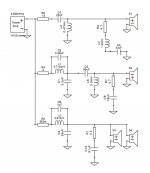
I want to build a 3-way ported speakers with two woofers and I would like to know your opinion on my crossover.
Woofers: 2x Dayton DC300-8 (in enclosure with 240 liters (8.5 cubic ft) just for woofers, bassreflex tuned to 25 Hz)
Midrange: Dayton RS150-4
Tweeter: Dayton RST28F-4
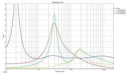
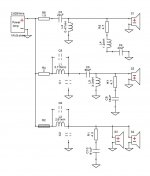
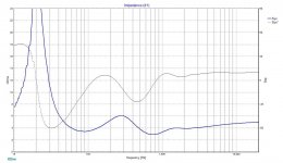
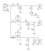
I was trying to have impedance curve as close as possible to 4 ohm (not less than 3.6 ohm) not to damage the amplifier as it can handle minimum 3.2 ohm. That is the reason of R2 rezistor in woofer section otherwise the impedance drops to 3.1 ohm. Also zobels and notch filter were used.
I was checking inverting polarity of mid speaker - there is quite good "deep" but I do not know if it is ok because the deep is a bit weird.
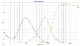
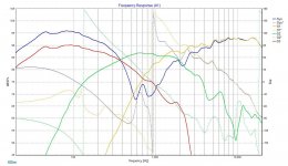
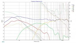
Impedance curves show peaks at frequencies about 300 Hz and 1900 Hz, so I suppose those are cutting frequencies, right? I was not counting them just trying to have frequency curve as flat as possible with phase of all speakers as close as possible.
Woofer section has a bit higher SPL as for a "baffle step loss".
I do not understand why tweeter takes so much power. Should not be that a woofer?
I will be very grateful for any comment or review of my crossover.
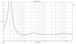
FRD and ZMA files are attached.
Thank you in advance.
Woofers: 2x Dayton DC300-8 (in enclosure with 240 liters (8.5 cubic ft) just for woofers, bassreflex tuned to 25 Hz)
Midrange: Dayton RS150-4
Tweeter: Dayton RST28F-4
I was trying to have impedance curve as close as possible to 4 ohm (not less than 3.6 ohm) not to damage the amplifier as it can handle minimum 3.2 ohm. That is the reason of R2 rezistor in woofer section otherwise the impedance drops to 3.1 ohm. Also zobels and notch filter were used.
I was checking inverting polarity of mid speaker - there is quite good "deep" but I do not know if it is ok because the deep is a bit weird.
Impedance curves show peaks at frequencies about 300 Hz and 1900 Hz, so I suppose those are cutting frequencies, right? I was not counting them just trying to have frequency curve as flat as possible with phase of all speakers as close as possible.
Woofer section has a bit higher SPL as for a "baffle step loss".
I do not understand why tweeter takes so much power. Should not be that a woofer?
I will be very grateful for any comment or review of my crossover.
FRD and ZMA files are attached.
Thank you in advance.
Attachments
")
The frequency range reproduced by the tweeter has little energy and you can use only for the tweeter a 4Ω speaker. The amplifier almost will not see the impedance drop in the tweeter range. The rest of speakers can be 8Ω and 16Ω.
In my speakers I use a 4Ω tweeter and mid and woofer of 8Ω.
In my speakers I use a 4Ω tweeter and mid and woofer of 8Ω.
It may work, and has been done this way for specific purposes. However if this is your first attempt at a crossover I'd have to say no, don't do things this way. You have your woofer and mid beginning with a capacitor shorting a Voltage source amplifier. Ie C1 and C2.
While it does look like you have a parallel notch filter in each case before these capacitors, unless this was intentional then you have to consider that any relief they offer is purely accidental. Same for the resistors. If you vary anything you may uncover the capacitor.
Speaking of which, the resistor on the woofers (R2) is probably best removed. One of the drivers has to act to set the level and there's no sense wasting power to achieve that.
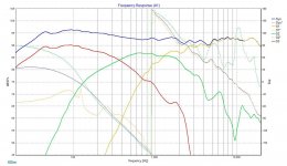
I used capacitors C1 and C2 as a part of low pas filter. Is that wrong? Should they be removed? If I do that and also remove capacitors of notch filter (C6 and C9) frequency response looks like in picture.
If I remove R4 impedance drops to 2.8 ohm.
If I remove R4 impedance drops to 2.8 ohm.
Attachments
I know you're wanting help but you probably don't yet realise just how complicated this is.
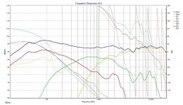
-20 is good, however it's about the whole response not just the peaks. You are not working to a target response which makes it more difficult.
Have you considered a series inductor and a series notch filter in parallel with the driver?
-20 is good, however it's about the whole response not just the peaks. You are not working to a target response which makes it more difficult.
Have you considered a series inductor and a series notch filter in parallel with the driver?
Are the frd files and zma files based on the manufacturer provided data? or have you measured them in your cabinet?
If they are pulled from the OEM plots, have you accounted for diffraction and time delay?
j.
I have no possibility to measure the data so I used the ones provided by Dayton. I did not accounted diffraction because I do not know how to do that. Time delay can by set by z-offset, right? I did not find the "depth" measurement for woofer and midrange so I am not able to set the offset.
- Home
- Loudspeakers
- Multi-Way
- Please review my 3-way crossover