Is Dayton Audio PS95-8 Fullrange good for the Frugel-Horn?
- By Edu cbm
- Full Range
- 7 Replies
Hello
I´m from Brazil and here we dont have access to very good speakers for home use, here we only have manufacturer for car speakers wich are not good for enclosures...
we have to import the good speakers, but with the dollar exchange rate for 5:1, even cheap speakers become very expensive for us, and we have the import taxes and shipping costs high too
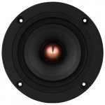
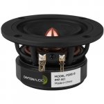
so i bought a pair of dayton audio ps95-8 3-1/2" Point Source Full-Range Driver from a friend who buy when he went to USA, and now i am thinking what i could do with them
-------------------------------------------------------------------
Question 1: Is dayton audio ps95-8 3-1/2" Point Source Full-Range Driver good for the Frugal horn?
i love the concept and think that a horn will make this speaker sound better and with more bass than a bass reflex box...
am i right?
if i´m not, wich enclosure could i build to get the most of this speaker (in terms of bass and in general)
--------------------------------------------------------------------
Question 2: will i need a subwoofer to use with them? the frugal horn alone will lack bass?
----------------------------------------------------------------------
https://www.daytonaudio.com/product/1241/ps95-8-3-1-2-point-source-full-range-driver-8-ohm
I´m from Brazil and here we dont have access to very good speakers for home use, here we only have manufacturer for car speakers wich are not good for enclosures...
we have to import the good speakers, but with the dollar exchange rate for 5:1, even cheap speakers become very expensive for us, and we have the import taxes and shipping costs high too
so i bought a pair of dayton audio ps95-8 3-1/2" Point Source Full-Range Driver from a friend who buy when he went to USA, and now i am thinking what i could do with them
-------------------------------------------------------------------
Question 1: Is dayton audio ps95-8 3-1/2" Point Source Full-Range Driver good for the Frugal horn?
i love the concept and think that a horn will make this speaker sound better and with more bass than a bass reflex box...
am i right?
if i´m not, wich enclosure could i build to get the most of this speaker (in terms of bass and in general)
--------------------------------------------------------------------
Question 2: will i need a subwoofer to use with them? the frugal horn alone will lack bass?
----------------------------------------------------------------------
https://www.daytonaudio.com/product/1241/ps95-8-3-1-2-point-source-full-range-driver-8-ohm
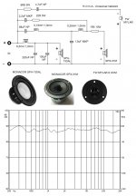
| Speaker Type | Full-Range |
| Nominal Diameter | 3.50" |
| Power Handling (RMS) | 10 watts |
| Power Handling (max) | 20 watts |
| Continuous Program Power | -- |
| Impedance | 8 ohms |
| Sensitivity | 85.56 dB @ 2.83V/1m |
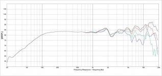
| Frequency Response | 110 - 20 000 Hz |
| Voice Coil Diameter | 20 mm |
| Magnet Weight | -- |
| DC Resistance (Re) | 7.1 ohms |
| Voice Coil Inductance (Le) | 0.63 mH @ 1 kHz |
| Resonant Frequency (Fs) | 119.8 Hz |
| Mechanical Q (Qms) | 7.33 |
| Electromagnetic Q (Qes) | 0.8 |
| Total Q (Qts) | 0.72 |
| Diaphragm Mass Inc. Airload (Mms) | 2.2g |
| Moving Mass Of Diaphragm (Mmd) | -- |
| Mechanical Compliance of Suspension (Cms) | 0.79 mm/N |
| Surface Area Of Cone (Sd) | 28.3 cm² |
| Volume of Displacement (Vd) | 7.08 cm³ |
| BL Product (BL) | 3.83 Tm |
| Compliance Equivalent Volume (Vas) | 0.94 liters |
| Maximum Linear Excursion (Xmax) | 2.5 mm |
| Drivers Mechanical Losses (Rms) | -- |


![IMG_3047[1].JPG](/community/data/attachments/996/996408-853c51f97870da0441ddcda4188b813b.jpg?hash=hTxR-Xhw2g)
![IMG_3049[1].JPG](/community/data/attachments/996/996409-669e698f4cc16b4c97ddb05e853620c5.jpg?hash=Zp5pj0zBa0)


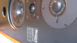
 . The dipoles are very untiring and natural to hear albeit their obvious limitations in Bass and transition to dome tweeters (are addressed in JohnK's Nao Note).


