There was a recommendation to add more capacitance at the output of capacitance multiplier, and subsequent unanswered question as why is this recommended:
https://www.diyaudio.com/community/threads/sissysit-r-3.371272/post-7112259
I decided to check actual circuit behavior and give reasonably correct explanation.
Every power supply has voltage change at its output under load and, for an audio signal, amplifier is dynamic load that pulls current from the PS, at the output signal frequency and load current. How much will PS voltage vary, depends on its internal impedance at the required frequency. This impedance is kept low, with help of the final output capacitor. Any voltage drop at the output capacitor is “filled up” from the first reservoir capacitor (and transformer + rectifier) through resistance between them. In case of simple CRC, there is usually 0.11 Ω.
Capacitance multiplier follows cleaned voltage after RC filter with smoothed ripple and noise, supplied to the base of regulating transistor (Darlington in this case). Output is at the emitter and it simply follows voltage present at the base. Every transistor needs, with increasing current, more voltage between base and emitter. So, if load increases, as base is at the steady voltage, emitter voltage must drop to get required Vbe increase for the larger output current. That’s why capacitance multiplier output voltage under load varies substantially, the same or even more than with the CRC supply and should have a large capacitor at the output.
Nobody at diyAudio measures a damn thing when power supplies are in question. So, I made some PSRR and transient response measurements for the mentioned capacitance multiplier – Mark Johnson & Gtose design:
https://www.diyaudio.com/community/...sy-capacitance-multiplier.297921/post-6031533
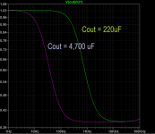
First point worth to mention: PSRR changes a lot with load current! Measured at 120 Hz with 5 mF capacitor:
Another point: large output capacitor (68 mF) increases PSRR at all load currents by 6 – 8 dB.
Measurement from 20 Hz to 95 kHz at 1.7 A load, for the Cap Mx assembled using breadboard, so actual circuit could be several dB better, but not much.

Note: PSRR is not a level below some reference, rather PSRR is ratio between two values and shouldn’t be expressed as a negative number. Yes, usual representation in various datasheets with PSRR as some -XX dB number is wrong!
Transient response was checked with 1.7 A square wave load at 250 Hz and 1000 Hz, with 470 uF as base and then with 5 mF and 68 mF output capacitors. We can see that, with the small output capacitor, output voltage drops immediately, while with larger output capacitor voltage drop is smaller and gradual. At higher frequency, where internal capacitor ESR is lower and load time is shorter, drop is even smaller. Yellow trace is output voltage and blue is voltage drop across the 0.33 Ω resistor at the active load.


We can conclude that, as output capacitance or frequency is increased, voltage drop becomes smaller. It is 130 mV with small output capacitor and 40 mV with largest.
In case of power amplifier, 10 - 15 mF is not an optimal value at the output of capacitance multiplier circuit. We should use 33 – 47 mF, as with the standard CRC PS.
https://www.diyaudio.com/community/threads/sissysit-r-3.371272/post-7112259
I decided to check actual circuit behavior and give reasonably correct explanation.
Every power supply has voltage change at its output under load and, for an audio signal, amplifier is dynamic load that pulls current from the PS, at the output signal frequency and load current. How much will PS voltage vary, depends on its internal impedance at the required frequency. This impedance is kept low, with help of the final output capacitor. Any voltage drop at the output capacitor is “filled up” from the first reservoir capacitor (and transformer + rectifier) through resistance between them. In case of simple CRC, there is usually 0.11 Ω.
Capacitance multiplier follows cleaned voltage after RC filter with smoothed ripple and noise, supplied to the base of regulating transistor (Darlington in this case). Output is at the emitter and it simply follows voltage present at the base. Every transistor needs, with increasing current, more voltage between base and emitter. So, if load increases, as base is at the steady voltage, emitter voltage must drop to get required Vbe increase for the larger output current. That’s why capacitance multiplier output voltage under load varies substantially, the same or even more than with the CRC supply and should have a large capacitor at the output.
Nobody at diyAudio measures a damn thing when power supplies are in question. So, I made some PSRR and transient response measurements for the mentioned capacitance multiplier – Mark Johnson & Gtose design:
https://www.diyaudio.com/community/...sy-capacitance-multiplier.297921/post-6031533
First point worth to mention: PSRR changes a lot with load current! Measured at 120 Hz with 5 mF capacitor:
- 0.2 A – 94 dB
- 0.9 A – 72 dB
- 1.7 A – 66 dB
- 2.5 A – 59 dB
- 3.5 A – 41 dB
Measurement from 20 Hz to 95 kHz at 1.7 A load, for the Cap Mx assembled using breadboard, so actual circuit could be several dB better, but not much.
Note: PSRR is not a level below some reference, rather PSRR is ratio between two values and shouldn’t be expressed as a negative number. Yes, usual representation in various datasheets with PSRR as some -XX dB number is wrong!
Transient response was checked with 1.7 A square wave load at 250 Hz and 1000 Hz, with 470 uF as base and then with 5 mF and 68 mF output capacitors. We can see that, with the small output capacitor, output voltage drops immediately, while with larger output capacitor voltage drop is smaller and gradual. At higher frequency, where internal capacitor ESR is lower and load time is shorter, drop is even smaller. Yellow trace is output voltage and blue is voltage drop across the 0.33 Ω resistor at the active load.
We can conclude that, as output capacitance or frequency is increased, voltage drop becomes smaller. It is 130 mV with small output capacitor and 40 mV with largest.
In case of power amplifier, 10 - 15 mF is not an optimal value at the output of capacitance multiplier circuit. We should use 33 – 47 mF, as with the standard CRC PS.
Attachments

This is true of adding bulk capacitance to the output of any supply - the multiplier circuit just gives you more filtering for a smaller net value of capacitance. One thing to keep in mind, though, is the the PSRR drops sharply with the increase of the noise on the signal. No worries with the 100 or 120 hertz ripple but RFI will pass through pretty much unaffected by the bulk filtering - unless very bad not something to cause issues with an amplifier but something to keep in mind if designing a supply for other purposes.
Hal
PS: As a very good general basic introduction to the subject, as well as a solid design: https://sound-au.com/project15.htm
Hal
PS: As a very good general basic introduction to the subject, as well as a solid design: https://sound-au.com/project15.htm
Not all amplifiers may be considered a dynamic load to the power supply. Most (all?) Class-A amps will simply pull a constant current from the power supply. The energy storage to cover dynamic spikes is not all that important for such amps. I have tested with with a scope hooked to the output of a Smooth-Like-Buttah (SLB) cap multiplier feeding a Class-A amp. I couldn't see much much of the audio signal on the SLB output, even though there was no extra storage capacitors in place.Every power supply has voltage change at its output under load and, for an audio signal, amplifier is dynamic load that pulls current from the PS, at the output signal frequency and load current.
Yes, mF as 1000 uF.@tombo56 - great post, good work.
Just to be sure: when you say mF you actually mean milliFarad, right? Not microFarad uF.
Jan
Not all amplifiers may be considered a dynamic load to the power supply. Most (all?) Class-A amps will simply pull a constant current from the power supply.
On the contrary, only some A class amps will pull constant current while playing music. In example, single ended with CCS, pulls constant current all the time. Most will have dynamic current change equal to the output current. Especially DEF amplifiers like SissySIT and LuDEF are wild beasts having about 2.6 times greater current change at one rail, due output semiconductors transconductance difference. SisySIT at the negative rail, LuDEF at the positive rail.
single ended with CCS, pulls constant current all the time.
This isn't really true.
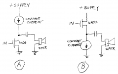
Figure 1 below shows two single ended amplifiers, each one has a constant current source. CCS-single_ended amplifier "A" on the left, pulls constant current from its power supply. CCS-single_ended amplifier "B" on the right, draws a non-constant current from its power supply. Supply current equals current through the loudspeaker (I = Vout/8ohms) plus current through the CCS. Since the amplifier output voltage Vout varies with time [hey that's music!], the total supply current varies with time.
_
Attachments
Last edited:
Oh, really?Nobody at diyAudio measures a damn thing when power supplies are in question.
Ha, ha, you are not nobody.Oh, really?

Especially you, Jan Didden and Linear Audio articles are exceptions and not to be mixed with the rest.
But, it is usual here to present power supply/regulator and attach no measurements.
The problem with this Youtube is that it is completely outdated. There are now regulators with a ripple rejection of up to 1,000 out to 1MHz!A good youtube video around this topic for anyone who wants to learn. Regards.
For line frequencies it's more like 1,000,000. Millivolts become nanovolts.
Jan
I see an inconsistency in the results (I am generally no great fan of cap-mults, but that's another debate).
In this pic for example, the left waveform looks like it should:

The waveform on the right has a positive spike at the positive edge, which in itself could be normal if the layout or the capacitor is imperfect (series inductance f.e.), but since the cap and layout are the same (in principle), the left one should display the same effect, just shorter.
In this pic for example, the left waveform looks like it should:
The waveform on the right has a positive spike at the positive edge, which in itself could be normal if the layout or the capacitor is imperfect (series inductance f.e.), but since the cap and layout are the same (in principle), the left one should display the same effect, just shorter.
Jan-
You are absolutely correct as to the availability of ultra low noise, high PSRR regulators (LT3042 etc) but that type of performance (<1uV RMS) is certainly not needed in audio applications. The capacitance multipliers being discussed can certainly be used be used as pre-regulators in applications requiring such low noise levels as they are very effective at low frequencies.
Hal
I admit I'm not either fan of capacitance multipliers. I favor super regulators.
Observed inconsistency is caused by several factors:
Signal averaging (16 averages) was used to exclude small variations as measurement setup is not professional one, so depends on which 16 averages was caught. There are some small peaks visible at 250 Hz measurements with 5 mF and 68 mF.
Longer time base + averaging at 250 Hz hides fast peaks, that were there if averaging is switched off.
Shorter time base at 1 kHz helps to catch and display those fast signal peaks.
Except that cap multipliers are not regulators. Their output fluctuates with current draw; a true regulator is rock-stable, less than a mV drop with an amp current delta (yes, that's less than 1mOhms Zout).Jan-
You are absolutely correct as to the availability of ultra low noise, high PSRR regulators (LT3042 etc) but that type of performance (<1uV RMS) is certainly not needed in audio applications. The capacitance multipliers being discussed can certainly be used be used as pre-regulators in applications requiring such low noise levels as they are very effective at low frequencies.
Hal
You can somewhat make up for the cap mux high Zout with a monstruous cap. If you like that kind of stopgaps.
Jan
Jan-
Apologies, you are correct - I really didn't make my comment as clear as i should have. In my mind i was thinking of:
a) power amplifier - no need for more than bulk, and possibly minimal EMI, filtering
b) Low level audio, such as preamps, tone controls etc, capacitance multiplier followed by standard regulator, good EMI filtering and design
c) non-audio, precision circuitry - capacitance multiplier followed by ultra low noise regulator, multi-approach EMI filtering and design.
Note: for both (b) and (c) a capacitance multiplier would be used to minimize space constraints primarily.
Hal
I know the video is old, but it is not a problem and not outdated. It is about why a capacitance multiplier is not really a capacitance multiplier. It is irrelevant that this an old video. To those who want to learn, knowledge is everywhere. (I believe you never would like to hear from someone to look at your old photograph when you were young and comment it is an outdated and there are better photographs of other people and will not look at this.) Regards.The problem with this Youtube is that it is completely outdated. There are now regulators with a ripple rejection of up to 1,000 out to 1MHz!
For line frequencies it's more like 1,000,000. Millivolts become nanovolts.
Jan
- Home
- Amplifiers
- Power Supplies
- Why is good to have large capacitor at the capacitance multiplier output