Hi folks,
I like to discuss with you what happens to an amplifier in case either the positive or the negative power supply is lost or the ground is disconnected.
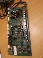
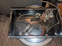
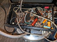
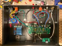
I recently figured out that my amplifier evaporates the magic smoke in case the negative power supply is disconnected and this is why I start the discussion.
After spending some time at the bench doing an autopsy, I went back to circuit simulation in order to figure out the root cause for some components destruction. I observed that once any power supply gets lost, my amplifier no longer works at all and operating points shift so that components get destroyed.
I don't like to bore you with my specific amplifier, but like to discuss amplifiers in general.
I need you to get my thinking straight, which went in confusing loops throughout the weekend.
Actually an audio amplifier is just a huge op-amp. Many op-amps support single supply operation and I believe an audio amplifier should support this, too. At least not burn down in case it happens (like a fuse blows). My expectation would be that ideally the output DC offset is half of the supply voltage and the signal is reproduced around this offset.
It believe it should be avoided that any unconnected power supply input is undefined floating around.
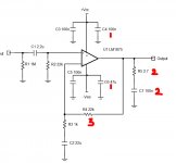
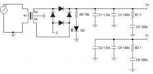
So my first idea was to connect diodes to ground so that there will be a path for the current (see ordinary diodes in the schematic).
This probably is a good idea.
In case either power supply gets lost, it will be clamped to a diode drop above or below ground.
Also, a pair of resistors in parallel to the diodes form a high impedance virtual ground in case of ground loss. May be good, too. However, this virtual ground would be a diode drop away from one of the power supplies in case of loss of the opposite power supply.
During the investigation I found out that in my amplifier all circuit blocks (CCS and current mirror) defining DC points are no longer functional once any supply or ground is lost.
This is partly because I was lazy connecting references to ground because having a ground plane makes this easy (case A in the schematic). bad idea obviously.
Most designers are using connection scheme B, which is independent of ground - far better than what I did.
Scheme C is also interesting, but has the disadvantage that power dissipation is doubled and components like transistors need to withstand twice the voltage.
However, I found out that this scheme is beneficial in some cases where scheme B would not work. It makes operation more independent of each other.
My observation so far is that some circuits may behave in a very unforeseen way.
The diodes avoiding floating supplies seem helpful, but still some circuits behave strangely.
For example the current mirror with EF helper transistor behaves strangely in my amp with only one power supply. This is having to do with the helper transistor. A plain CM or Wilson CM instead works well.
Also, the cascodes of the CCS no longer work as cascodes, but become diodes instead sometimes and all kind of other freaky things going on.
What do you think?
Do you consider power supply or ground disconnection in your designs?
How do you handle this?
What do you think about my observations and ideas?
Here is the example schematic showing some CCS I use to help me thinking:


