Many turntables are equipped with a strobe light. The platter has marks that are illuminated by a pulsed light source. If the rotation speed is exactly such that the marks move exactly their step size in a time equal to the flash period, then the marks will appear to be stationary. This property is used to check disk rotation speed. Often the strobe lamp is powered by mains voltage, so mains frequency error will result in speed error. It is desirable to stabilize the frequency of the stroboscope with quartz.
When powered from the mains, the strobe lamp flashes 100 (50 Hz region) or 120 (60 Hz region) flashes per second. To obtain an accurate speed of 45 RPM or 78 RPM, it is impossible to find an acceptable integer number of marks. Therefore, these speeds are set approximately.
For the 50 Hz region:
Nominal speed: 33 1/3 RPM, real speed: 33 1/3 RPM, number of marks: 180
Nominal speed: 45 RPM, real speed: 45.113 RPM, number of marks: 133
Nominal speed: 78 RPM, real speed: 77.922 RPM, number of marks: 77
For the 60 Hz region:
Nominal speed: 33 1/3 RPM, real Speed: 33 1/3 RPM, number of marks: 216
Nominal speed: 45 RPM, real speed: 45.000 RPM, number of marks: 160
Nominal speed: 78 RPM, real speed: 78.261 RPM, number of marks: 92
To get an accurate value for any speed, it must be possible to fine-tune the flash rate of the strobe in small steps. All 3 sets of marks are not always applied to the platter. Sometimes there is only one set, then to check different speeds, you need to change the strobe frequency. All this requires some flexibility from the stroboscope.
The stroboscope is based on one of the smallest microcontrollers ATtiny12L. To generate the flash frequency of the LEDs, a software-implemented NCO (Numeric Controlled Oscillator) is used, which is usually one of the components of a direct digital synthesizer (DDS). This provides a frequency step of about 0.001 Hz, which allows any quartz to obtain any output frequency within this accuracy. This is an advantage of NCO over a simple divisor.
The stroboscope has the ability to generate 4 different frequencies, which are selected using the SEL0 and SEL1 inputs. Each of these frequencies is specified in the source text as a constant and can be any. The constants for the frequency code are calculated automatically. As the initial data, you must enter the desired speed with an accuracy of 0.001 rpm and the number of platter marks. For example, 50 Hz turntables typically have 180 marks for 33 1/3 RPM and 133 marks for 45 RPM. Based on this data, frequency codes are calculated at the compilation stage. For a speed of 33 1/3 RPM and a number of marks of 180, the LED frequency will be set to 100 Hz. And for a speed of 45 RPM and a number of marks of 133, the frequency will be set to 99.750 Hz, which will give a speed of exactly 45.000 RPM. The speed of 78 RPM can be checked on any set of marks, 180 will be set to 234 Hz, and 133 marks to 172.9 Hz.
#define FREQ_1 FREQ(33333, 180) ;preset 1
#define FREQ_2 FREQ(45000, 133) ;preset 2
#define FREQ_3 FREQ(78000, 180) ;preset 3
#define FREQ_4 FREQ(78000, 133) ;preset 4
In order for the marks to be sharp, the duration of the flashes must be short. The duty cycle of the LED flashes should be 4 ... 16, shorter flashes give a clearer picture of the stroboscopic marks. In the final version of the firmware, the duty cycle is set to 16.
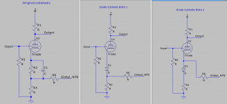
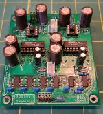
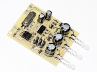
There is another problem - the stroboscope can become a source of interference. A pulsed current flows through the stroboscope LEDs, and if the stroboscope power wires are long and close to the signal wires, interference may occur. Another possible cause of noise is that the LED supply current can create a pulsed voltage drop on the ground wire. For this reason, some turntables have the ability to turn off the strobe. To eliminate the problem of interference, it is desirable to localize the pulsed currents within the stroboscope board, and make the current consumption of the board as a whole constant. To obtain a constant current consumption, a current source is used, implemented on transistors VT1 and VT2. This current source charges the capacitors C6, C7, C8, from which the LEDs VD1 ... VD3 are powered. If the voltage on the capacitors exceeds a certain threshold (about 4 V), the parallel regulator U3 (TL431) turns on, ensuring a constant consumption even without working LEDs. The simulation graph shows that with a total LED pulse current of about 60 mA, the total consumption is about 16 mA, and it is constant.
The stroboscope board can be powered by an external voltage of 5 V. For versatility, a U1 stabilizer is installed on the board. As a result, any voltage within the range of 7 ... 20 V can be used for power supply. If there is a voltage of 5 V, the U1 stabilizer can be excluded.
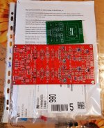
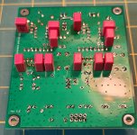
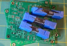
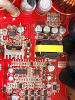
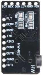
The stroboscope printed circuit board is single-sided, 30 mm x 40 mm in size. In order not to drill any holes at all, all parts are soldered in the manner of SMD. Electrolytic capacitors are soldered with shortened and slightly bent leads to the pads. The programming pins are soldered as follows: first, the plastic moves up, the pins are soldered to the pads, then the plastic moves down again.
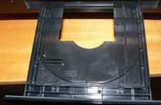
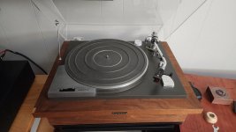
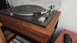
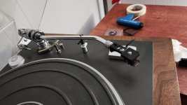
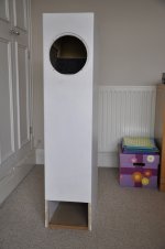
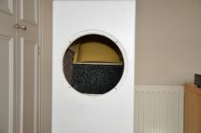
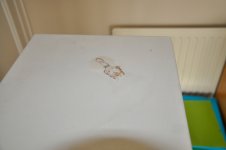
The convenience of this stroboscope design was confirmed during the repair of the Bang & Olufsen Beogram 2000 turntable. He has only one strobe scale, which contains 180 marks. There is no built-in strobe light. For a speed of 33 1/3 RPM, you can use, for example, a neon lamp powered by a mains frequency of 50 Hz. But how to check the speed of 45 RPM? With this strobe, it's simple - you can add the output frequency FREQ (45000, 180), which will give 135 Hz. The marks on the Beogram platter are very high quality, so it was possible to check how the duty cycle of the LED pulses affects the sharpness of the edges of the mark image. With a duty cycle of 4, the marks are quite blurry. With a duty cycle of 8, it gets better, with a duty cycle of 16, the image is close to ideal, a further increase in the duty cycle is not required. This duty cycle is set in the final version of the stroboscope firmware.
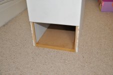
The stroboscope can be built into the turntable or made as an external device. In the second case, you can use, for example, a phone charger as a power source.