I asked a question here a long time ago regarding PCB for a Quad 405 clone. I built one and I like it very much, yes its an old design and there is a world of newer designs to utilise but each to their own.
I want to build another and gift the one I built to a friend, for the next one I would like to use 2x300VA toroid trafo and Elna 10,000uF caps that have been sitting on a shelf for a year. I have some extrusion as used in these cases Uniobox 2 - electronics enclosure kit - Lincoln Binns and want to build two mono units.
My questions are thus; where to find a good design for the two PSU required?
I would like to modify the amplifier circuit design to Snook or Net Audio, the boards in my amp are copies of the first Quad issue, the LJM clone. I see there is a copy of the 405-2 board available, which PCB is likely to need the least track cutting and component moves? On the 405-2 clone PCB I see that the input and output connections are spaced further than the first issues, design modification to avoid noise?
I read this thread from 2006 but nearly all of the links are broken; https://www.diyaudio.com/forums/solid-state/79508-quad-405-2-clone.html
Here you go! Higly sought Class A dynamic biasing 80W amplifier PCB Quad 405 MK2 1pc ! | eBayHi Ian
Also looking for these PCbs,
Holding thumbs.....
I contacted the seller Jims Audio and asked if the PCB power transistor positions matched the holes on the super cheap "MK1" kits on offer, he said yes they do.
The description is ludicrous, "higly sought Class A dynamic biasing 80W amplifier PCB Quad 405 MK2" but it is the PCB you and I might be looking for.
Thank you. All reading is good, with many sources it may lead to confusion but it is good to disseminate the information from different authors/engineers.

I bought the older version from that store, the material quality is good and the plating and hole postions are spot on. If the other (newer revision) is of the same quality you and I will be satisfied for sure. You are going to need the heatsink brackets unless you intend to fashion a pair yourself. I have not looked to see if anyone sells them seperately, you could ask the seller, he got back to me within the hour last Saturday.
I have still not decided if I will go ahead, probably will. The board I linked to is a straight copy of one of the later boards, I am too lazy to look at the various versions to nail it down.
Perhaps the clincher is the extra distance between input and output, the revison by Quad can't have been done just for fun.
It is a very long time ago I build a 405 clone, but the power supply section contained only the mains transformer, a 25A bridge rectifier, and a pair of 10000uF/40V capacitors, if I remember correctly. No need any regulated PSU.
I have ordered the "higly" sought after boards from Jims. I have the images off the vendors ebay listing but I will wait until I see them up close to try and identify which Quad issue they have been copied from. They are Quad 405-2, that much is certain but early or late I do not know.
I bought a pair of the Jim's boards.
But ended up buying and modifying some clone mk1 boards instead.
Partly because I wanted to mod further than Jim has,
and partly because the clone boards come pre loaded with components,
which saves time chasing components and loading the boards.
But ended up buying and modifying some clone mk1 boards instead.
Partly because I wanted to mod further than Jim has,
and partly because the clone boards come pre loaded with components,
which saves time chasing components and loading the boards.
John you also saved yourself a heatsink problem. Boards arrived today and from the back of my mind came a recollection of something I read on the DADA site years ago. The early Jims board is 90x126mm, his 405-2 board is 82x119 so the heatsink/bracket for the early boards that is easily available as a seperate item and fairly cheap is no good for me. For those without the luxury of a metal working shop it means that something that should have been building by numbers now has real work involved.I bought a pair of the Jim's boards.
But ended up buying and modifying some clone mk1 boards instead.
Partly because I wanted to mod further than Jim has,
and partly because the clone boards come pre loaded with components,
which saves time chasing components and loading the boards.
I will have to source 2"x1"x1/4" unequal angle 6063 alu and have to route or mill the cutout along the 2" leg for the TR7&8 and those components between them.
To avoid having to do no more than drilling requires angle with one leg 1.25" to provide correct mounting for the TO3 devices. It also means that the 2 TO220 devices would have to have their own plate or other off the shelf heatsinks, similar to the Net Audio boards.
I wonder how many jobs get bogged down because of the need for more complex machining procedures, chain drilling rectangles from 1/4" stock is no fun.
I started out on this job with the intention to build from stock components and have an enclosure with the minimum of effort on my part but find myself needing to put effort into the metal parts.
Heres the two boards side by side with one of the TO3 indexed. There is another variant on the auction sites from Jims, perhaps the orginal clone before they all started selling them, this one is close to the OEM in dimension unlike the ones I bought a long time ago. Class A dynamic biasing 80W amplifier PCB Quad 405 2pcs | eBay
Attachments
Last edited:
I am going to mock up the enclosure and layout that has been in my mind for a while because I need some advice regarding heat and also wiring routes. It won't be an Autodesk drawing that much you can be sure of.😀
I'll crack it on with it when I return from the grocery store this weekend.
I'll crack it on with it when I return from the grocery store this weekend.
Bad luck Ian.
Yes, that's another advantage I forgot about.
You can modify the Ali with an Angle grinder, files and sandpaper....
Probably quicker than getting someone to mill it.
As I mentioned in my other thread on the 405's, I wanted to delete the Current Limiting completely. Which I suppose makes it a Quad 405-3 ; or at least 2.5 🙂
This is the feature of the amp which is most 'trash talked' by far on the internet. And I thought it sounded better without it. Although it's hard to be sure of these subjective things.
To some extent, it doesn't matter which version of the boards you get, if you're going to modify them a good bit. And the Mk1' clones I got were actually good quality boards. Significantly better than the old Quad originals.
You can't be sure what's inside the power transistors, but I've only ever blown 1 up - and that was with mental levels of sub bass into 2x12" drivers in parallel.
I also managed to fit a couple of these clone boards into a genuine 405 case - which several people on the internet say you can't. You have to trim the edges a bit & be careful - but it worked with the ones I got.
I have four of the MJ15024G devices that came with replacement boards from Douk Audio a few years ago. I ordered 2 PCB but there was only one in the packet. I queried the order and they sent me two complete kits of parts! I ended up with three PCB and parts for two amplifiers. I did not use them as I had stock enough barring the electrolytics which needless to say I ordered from Mouser.
I haven't the heart to dremel one of the caps of the MJ transistors to take a peek inside. I should just build them up and test run them out of interest on a winter night.
I haven't the heart to dremel one of the caps of the MJ transistors to take a peek inside. I should just build them up and test run them out of interest on a winter night.
I am the man that many are envious of, I have a Bridgeport Interact in my workshop. It spoils the fun though, the object of the exercise was to assemble a finished amplifier with little more than soldering iron and cordless drill.Bad luck Ian.
Yes, that's another advantage I forgot about.
You can modify the Ali with an Angle grinder, files and sandpaper....
Probably quicker than getting someone to mill it.
As I mentioned in my other thread on the 405's, I wanted to delete the Current Limiting completely. Which I suppose makes it a Quad 405-3 ; or at least 2.5 🙂
This is the feature of the amp which is most 'trash talked' by far on the internet. And I thought it sounded better without it. Although it's hard to be sure of these subjective things.
Things have changed yet again, my friend don't want my original build, even for free. His interest is piqued by what I am going to build and he is willing to stump up the money so I ordered some more of the copy of a copy PCB's.
Its a brazen world when a design is improved and copied then copied again by another party.
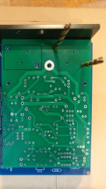
I have been tracing the PCB layout and see that it is precisely the same as that offered by a builder/supplier in Northern Europe complete with flipping the input, placements for 100uf electrolytics between the fuses and so on.
The current limiters and caps C18 & C19 have placements but to remove them from circuit R35 & R36 have shorting links placed.
I read that with TR9 & TR10 17556 devices the current limiters have a place but with the MJ15003G commonly used there is enough overhead not to require them. So much information and also some amount of contradiction to be found on this amplifier.
Yes, the original intent of the current limiters was to protect the old 17556 transistors. And then - they were only needed when driving low impedances. This was partly because these amps were used a lot in pro audio, where they were thrashed and expected to survive everything.
Now these devices are 40 years out of date, and have been replaced by much more rugged ones - there's no point in the current limiters.
Most amplifiers don't have/need these anyway...
Now these devices are 40 years out of date, and have been replaced by much more rugged ones - there's no point in the current limiters.
Most amplifiers don't have/need these anyway...
- Home
- Amplifiers
- Solid State
- Enjoyed my clone Quad 405 so much I want to build another