Hi @IanWB, how did it went with your Quad clone build? Looking for a pcb or ready built kit to add the latest mods and improvements. Ist the Dada pcb, the one you bought following all the mods and upgrades? Cheers!
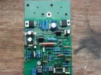
I've been wanting to refresh the PCBs in my Quad 405s (due to 40 years of repairs, refreshes and mods taking their toll), so I've now layed out a PCB, which includes the selected mods I have implemented on the originals. Once I've finished final checking I'll get a few made to test fit and performance.


Hi richb, you've ended up pretty close to where I ended up.
I finished mine about 4 years ago, and they've been running great since.
I've got 4x Quad 405's running some active speakers - In 3 original Quad 405 cases and one case I built.
They're a mix of the old original boards and new clone boards all modified as below.
You've gone a bit further, but we're close.
Good luck with your build.
Attachments

Hi, I am also building this board but have a few problems, I have tried to power it up but keep blowing r33 and r38 plus the tip42c! fuses do not blow. any ideas where I should look for the problem? cheersLess transistors to buy building unnecessary and unwanted SOA, more money for components or beer😉.
Attachments
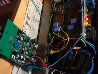
Are you powering it up as pictured? The DC feedback will work without TR9/10, but certainly not without the opamp.Hi, I am also building this board but have a few problems, I have tried to power it up but keep blowing r33 and r38 plus the tip42c! fuses do not blow. any ideas where I should look for the problem? cheers
Also, what supply voltage did you use? It will need in excess 25v on the +ve rail for Tr1 to begin to provide current to Tr2 (plus enough +-supply for the opamp), otherwise again the DC feedback loop will not operate as intended.
Yes I powered it up as the picture and power was from the 405. right I shall put the opamp in, and try again thanksAre you powering it up as pictured? The DC feedback will work without TR9/10, but certainly not without the opamp.
Also, what supply voltage did you use? It will need in excess 25v on the +ve rail for Tr1 to begin to provide current to Tr2 (plus enough +-supply for the opamp), otherwise again the DC feedback loop will not operate as intended.
Last edited:
The DC current consumption is around 100mA, so you should easily get away with say 50 Ohm in place of the fuses for a ~5v voltage drop in each rail (with 0.5W dissipation), and this may save devices from 'rapid disassembly' in case of error.Yes I powered it up as the picture and power was from the 405. right I shall put the opamp in, and try again thanks
Last edited:
I did have to make a substitution for T2, I used a BTA10-600C instead of a T2800b, do you think that might cause an issue? what wattage for the 50 Ohm? thanks againThe DC current consumption is around 100mA, so you should easily get away with say 50 Ohm in place of the fuses for a ~5v voltage drop in each rail (with 0.5W dissipation), and this may save devices from 'rapid disassembly' in case of error.
I think that is a common substitution. Some useful information here, see the section 'Output offset voltage clamp'. If I recall correctly I have tested them according to the method described.I did have to make a substitution for T2, I used a BTA10-600C instead of a T2800b, do you think that might cause an issue? what wattage for the 50 Ohm? thanks again
However for your initial DC test, you can disconnect the clamp circuit and load. As indicated, the resistors will dissipate 0.5W, and should only be needed briefly until you can ascertain correct DC conditions or not. Maybe a couple of 1/2W 100Ohm in parallel will suffice for this.
Ok, so the 50 Ohm resistors kept most things in check, did not toast the drivers but did cook R8 a bit.The DC current consumption is around 100mA, so you should easily get away with say 50 Ohm in place of the fuses for a ~5v voltage drop in each rail (with 0.5W dissipation), and this may save devices from 'rapid disassembly' in case of error.
R7 (and equally R8) should each be dissipating around 0.5W continuously, so will get quite warm over time. Typically you'd use 2W resistors spaced above the board by around 1cm to aid dissipation.Ok, so the 50 Ohm resistors kept most things in check, did not toast the drivers but did cook R8 a bit.
Did you check some DC voltages when powered so? For instance, there should be ~20mV or so at the output (without the power and signal grounds shorted together when on the bench), just over a volt at the opamp output, TR8 base a diode drop below ground, and TR7 collector ~2 diode drops above ground.
for sure there is dc somewhere! the vellman does not like it, the drivers and r30/31 also got a bit warm. I will check at the points you mentioned and get back. cheersR7 (and equally R8) should each be dissipating around 0.5W continuously, so will get quite warm over time. Typically you'd use 2W resistors spaced above the board by around 1cm to aid dissipation.
Did you check some DC voltages when powered so? For instance, there should be ~20mV or so at the output (without the power and signal grounds shorted together when on the bench), just over a volt at the opamp output, TR8 base a diode drop below ground, and TR7 collector ~2 diode drops above ground.
Attachments
1.874v at the outputR7 (and equally R8) should each be dissipating around 0.5W continuously, so will get quite warm over time. Typically you'd use 2W resistors spaced above the board by around 1cm to aid dissipation.
Did you check some DC voltages when powered so? For instance, there should be ~20mV or so at the output (without the power and signal grounds shorted together when on the bench), just over a volt at the opamp output, TR8 base a diode drop below ground, and TR7 collector ~2 diode drops above ground.
.687v at the opamp output pin6 no earth and 1.874v at the speaker output with earth.R7 (and equally R8) should each be dissipating around 0.5W continuously, so will get quite warm over time. Typically you'd use 2W resistors spaced above the board by around 1cm to aid dissipation.
Did you check some DC voltages when powered so? For instance, there should be ~20mV or so at the output (without the power and signal grounds shorted together when on the bench), just over a volt at the opamp output, TR8 base a diode drop below ground, and TR7 collector ~2 diode drops above ground.
I don't know what you mean by "no earth" and "with earth". It looks like you've connected the board ground to chassis ground with that green lead in the picture above, which is always needed..687v at the opamp output pin6 no earth and 1.874v at the speaker output with earth.
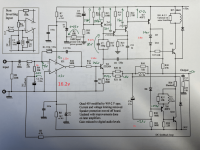
How about you annotate the circuit diagram with some voltages so we can see the whole picture, but certainly those voltages aren't as they should be.
sorry I misunderstood your previous post with the comment (without the power and signal grounds shorted together when on the bench), I will try and get some more readings today.I don't know what you mean by "no earth" and "with earth". It looks like you've connected the board ground to chassis ground with that green lead in the picture above, which is always needed.
How about you annotate the circuit diagram with some voltages so we can see the whole picture, but certainly those voltages aren't as they should be.
Hi, these are the readings, Opamp pin6 1.568v, output 2.3v, Tr7 base 3.946v and Tr8 collector 1.988vI don't know what you mean by "no earth" and "with earth". It looks like you've connected the board ground to chassis ground with that green lead in the picture above, which is always needed.
How about you annotate the circuit diagram with some voltages so we can see the whole picture, but certainly those voltages aren't as they should be.
Nowhere near enough information to diagnose!Hi, these are the readings, Opamp pin6 1.568v, output 2.3v, Tr7 base 3.946v and Tr8 collector 1.988v
Compare with this (rough hand calculations, no need for 4-digit precision):
I have added some more figures but this diagram does not match my board.Nowhere near enough information to diagnose!
Compare with this (rough hand calculations, no need for 4-digit precision):
View attachment 1095008
Attachments
- Home
- Amplifiers
- Solid State
- Enjoyed my clone Quad 405 so much I want to build another