Dali Concept 8 woofer configuration

Good evening all,

I got a pair of these Dalis as part of a recent rubbish collection, ie for free.

First thing I noticed was there are 2 ports, front and back, for the 2 woofers and reading online seemed to suggest this Dali series used separate enclosures for each woofer.

However removing the woofers showed that there is only one woofer enclosure with 2 ports. Why would Dali do this? A first inspection shows the 2 woofers are wired in parallel. Is it just for looks?

Cheers, sp

PPI 2300AM

What would cause this on Q16 ?

Is it from stress or the legs being bent and then bent back ?

Everything appears to be factory ampnhas never been repaired as far as I can tell .

The client bought the amp off someone and wanted it checked over before install .

I cleaned the wire strands from the board that I found so far

Attachments

  • 1486398B-7B3B-466C-891E-038D3CED3A01.jpeg
    1486398B-7B3B-466C-891E-038D3CED3A01.jpeg
    527.5 KB · Views: 130
  • 3962F72D-6ED7-44D4-9F41-1175DC56DF13.jpeg
    3962F72D-6ED7-44D4-9F41-1175DC56DF13.jpeg
    520 KB · Views: 112

Measuring bias (Cyrus amp)

From the diagram below, there appears to be a connector that allows for bias to be measured.

Am I correct that to do that I need to remove the jumper (I will check the board tomorrow morning) and connect an DVM between those point (set to amps) to measure the current?
The VR allows the bias current to be set - can anyone tell me what this should be?

Attachments

  • bias query.jpg
    bias query.jpg
    104.1 KB · Views: 176

PeeCeeBee V4 GB!

Hello guys!

A fresh new PeeCeeBee is here, the V4! In this thread group-buys for the printed circuit boards are arranged.

It's a Lateral MOSFET based Class-AB amplifier with symmetrical "current feedback", evolved from from the diverse PeeCeeBee series, and now with excellent sonics coupled with excellent looks. 🙂

The new design is electrically and sonically a step forward from the "stubbornly" simple but very good sounding designs released in the original PeeCeeBee thread. I say a step forward partly because it incorporates some extra well-known techniques to handle some of the problem areas in the old designs and allows a quicker and safer mode of set-up and operation, but mostly because while doing so it didn't become a fatigue-inducing clinical sounding amplifier. The layout is designed by myself and the amplifier is very stable, both thermally and electrically. The amplifier has similar sonic signature to the previous peeceebees in the mid and high frequency band, but the low-frequency performance has been substantially improved so that it can be used as a full-range amplifier with effortless bass as well as beautiful midrange and highs.

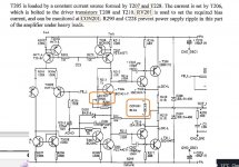
It uses a simple but effective diode-clamp based soft-clipping so that occasional overloads don't bother listening enjoyment. The two jumpers, when open, remove the chance of overloading Q9/Q10 while setting-up. The constant current sources keep the input/VAS bias much less affected by power supply variation during loud playback and/or mains fluctuation.

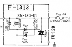
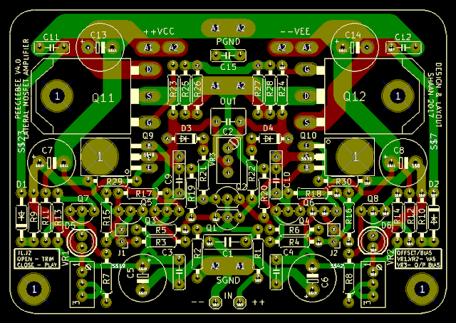
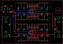
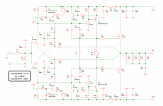
The following two screenshots show the design:

NmP6djgiQemEEJ6ulRHneov_72vVjiTZ9m4BI3cpO2QfjeALR5SlxKm8w0Gi1XCOE4CK5j0wXDgvFAs=w640

79M-Sjnh5trf3F_kybX_kqhk2f0YDxv8R5qIQNxPcSLeHsp_RCwc-LA8Y6ekX462vT1igjCUtzWiah4=w640

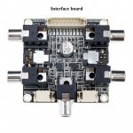
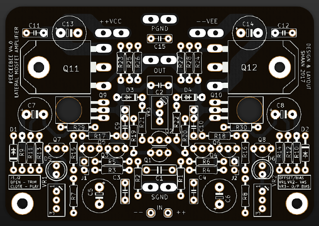
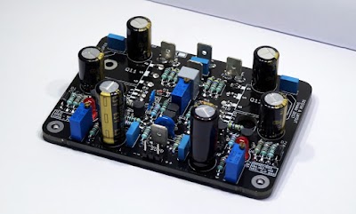
This is how the PCB looks in real world:

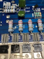
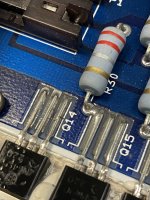
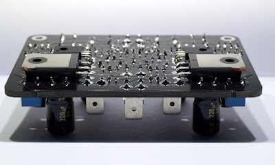
A fully assembled channel:


Some specs (measured with generic components/passives and basic unregulated linear PSU):
Maximum Power - 50WRMS/90WRMS into 8R/4R load with +/-35V PSU
Maximum allowed PSU voltage for 4R operation - +/-35V (with default clamp diodes and BD BJTs for Q9/Q10) and +/-42V (with higher voltage rated clamp diodes and MJE BJTs for Q9/Q10)
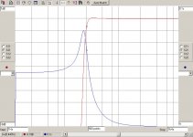
Frequency response(simulated) - ~2Hz to ~800KHz (-3dB)
AC gain - 23 (27dB)
DC gain - Unity
Input level for 50WRMS into 8R - 1VRMS
THD 100Hz 10W - 0.0005%, 1KHz 10W - 0.001%, 10KHz 10W - 0.002%
Slew Rate - 100V/uS
SNR - >100dB
Offset variation - +/-10mV

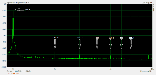
Screenshot of 1KHz THD spectrum (10W into 8R resistive load, 0.002% source THD):
nBqxTvAn3leWaiaw0BxzZnGnoMSmcwOihGFiLyx2lDkHB9puaaCMxlO8C8rfYXBP7BjLFiJmCNPjWg8=w640
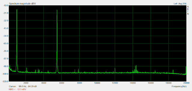
Screenshot of 1KHz + 5.5KHz IMD spectrum (1.7W into 8R load):
Sk9ZuWGXEtFqEJcykNQKpl9qe03Hl58IhLL5OHWrQAbtGe4UA3Jl92Pv-YsnkN_uQd1ZxPH-D6iPxC4=w640

__________________________________________

Group Buy Information:

The PCBs are 92mmx64mm 2-Layer and I plan to batch-print 50, 75 or 100 PCBs depending on interest and how many people join in the GB list. The boards are made with 2.4mm FR4, 60micron copper, HASL finish, white silkscreen and black solder mask, as shown in the above pictures.

> The PCBs cost US$10 a piece.
> After the GB list is full, each user will be contacted and sent the first invoice for PCB cost, and the rest (including shipping charge, packing and processing charge and PayPal charge) is to be paid before shipping the boards, for which the second invoice will be sent.
> International payments are accepted through PayPal and payments from within India are accepted through bank account transfer/deposit, NEFT etc.
> Delay between placing the batch order to PCB plant and delivery of the boards to me will be 18-20 days.


Shipping Information:

Two forms of shipping available. International Air Parcel and Registered Post. Former takes about 15-20 days to deliver and the latter takes about 30-40 days. Both support tracking.

_____________________________________________________

GB1 (April 26 2017)
--------------------------------
Update: Pending members and anyone wishing to join, Please notice:
PM/invoices will be sent up-to 5th May.
Last day of confirming order is 7th May.
PCBs will be ordered on 8th May.

Update(May 9 2017): Total 120 boards ordered. There are still 10 spare PCBs so join in if interested in a couple.
Update(May 11 2017): GB list full. No new entries are being taken until June 1 2017.
GB1 Ended.

--------------------------------

GB2 (June 15 2017)
-------------------------------
Second group buy has started.
GB2 Ended.

-------------------------------

GB3 (Sept 12 2017)
-------------------------------
Third group buy is now open for entry. Join in if interested!
GB3 Ended
-------------------------------

GB4 (Dec 23 2017)
-------------------------------
Fourth group buy has started.
GB4 Ended.
-------------------------------

GB5 (Aug 17 2018)
-------------------------------
Fifth Group Buy arranged. Boards available.

_____________________________________________________


Important Links:

Download Latest BOM for PeeCeeBee V4 >Here<

Download Setup Guide And Component Indication >Here< (Follow this to populate and start the PCBs)

Heat Sink Drill Template >Here<

Thanks.
shaan
🙂

Attachments

For Sale FS Scak Speak Sonus Faber Cremona units in KIT

UPDATED SALE.
Here for sale some Sonus Faber Cremona units.
Some units came from my Cremonas (damaged when my son pushed the dust cap of a woofer with his finger). A pair of woofers came from SF SAT. I will explain:

2x SF Cremona Tweeters. Perfect condition. No damages. They are used and in perfect working and cosmetic condition.
Asking 100€ +pp fees + shipping for the pair


2x SF Cremona Scan Speak 18W8531/G03 Woofers from my Original Cremonas.
One was repaired because the dust cap was damaged by my son. Speakers leads changed as well. Everything was repaired in a Professional service. I can provide invoice.
They measure the same. Perfect working condition. Some minor cosmetic issues (7/10).
Asking 190€ +pp fees + shipping for the pair


2x SF Cremona Scan Speak 18W8531/G03 Woofers
This pair of woofers came from one friend from SF SAT.
The owner coated them. They measure the same than original ones.
Perfect working condition. Average looking condition due to coating (5/10)
Asking 160€ +pp fees + shipping for the pair


I can make lots at discounted price and I can include for free a pair of front baffle for woofers
Each (mm) 758H x 210W x 19D Capable for 2x Scan Speak 18W8531 woofers and a jantzen Ø100mm Bass Refflex port (Ø138,50mm hole)
  • Like
Reactions: vassilis1984

1978 Rotel RA-1412 - slight hissing and pops in the headphone port

Hello!

I just bought this 1978 Rotel RA-1412. Its my first vintage amp and am pretty excited. So far so good aside from a couple things. I noticed while listening through one of the headphone ports im hearing a slight hiss and some crackle pops but its not consistent... only seems to happen once and awhile for a few minutes. I dont hear it when I source isnt playing but it could be by chance.

The way im getting the source is like this: hi-res audio from Windows PC> out through an optical cable> into a newer Rotel RA12 > Pre-Out > to RA-1412 Aux in.

Any place I should look to improve the noise?

The buttons on the right side of the unit (which picks the source) are also kind of finnicky and stick. The bottom button pops completely off if I push it in all the way and I push another button above in. Anyone know where I can find the parts to replace the switch?

Thanks again for everyone's time!

TDA1541A DAC Project Discussion

Hi,

I am sharing the file I got from my friend, it's a TDA1541A DAC with multiple input interface including I2S.
Also, for convenience there is a InterActive BOM that helps a lot while soldering components.

The attached .Zip file contains
A) GERBER files in Zip, ready for fabrication.
B) BOM in HTML.

Please let me know if there is problems.

Regards,
J


1664916361442.png
1664916324241.png

Attachments

Need Some Advice on Caps to use in Nikko Alpha ii Filter Caps

Hello, I have a set of two different brands of capacitors to install in my Nikko alpha ii power amp and can't decide which are better to use.
When the amp was new, it came with 10,000uf 63V 85 degree ones that had been changed out to others before I got the amp.
The ones that were in it when I got it were Jamico 10,000uf 100V 85 degree units.
I am doing a total re-cap of the entire amp and figured I would replace the filter caps as well while I have it all apart.
I purchased a kit with all caps for the amp, and have no issues with any of them except the filter caps..... and reading all of the forums has got me a bit confused.
Have new caps from Mouser here or new caps that came with the kit.
The choices are: EKMH630VSN103MA50S Nippon United Chemi-Con 10,000uf 63v 105 degrees or Kemet ALC70A103EH100 10,000uf 100v 85 degrees.
I have read some bad things about the Kemets used as power supply filter caps, but not sure if it pertains to these particular ones. Specs are not too bad on either....
So hoping I can get some suggestions from those who know more about this than I do.

Thanks!!!
Russ

Sonos/IKEA Symfonisk hack

Hi there,

I read this article about hacking the Sonos / IKEA Symfonisk, and thought I'd try it with a nice old radio I have in my kitchen. It earns its keep as a decoration alone, but it sure would be nice to get it playing as well.

Now, the first issue that I've run in to (I'm sure there will be more), is that the radio only has one single woofer, while the Sonos looks like some sort of bi-amp setup. I'm not familiar with such. Would it be possible to wire both sets of cables to the same woofer?

From makezine.com:
image031.jpg

Project Madness

Hello all

Everyone who know me understand that I am a big Audio Physic fan, so when I see this one launched at hi end München show, I am getting really stunned... at every point. There are many things that tick boxes here

https://www.audiophysic.com/en/medeos/
  • Point source, or really close to point source, the whole passband down to around 300 Hz is managed by the central 3 drivers really close together, the other drivers symmetrically around this point.
  • Lot of cone area in the mid-bass up to 300 Hz, must leave us with unreal dynamics, and there is nothing like lots of cone area
  • Woofers for midbass located low and high which means it triggers different room modes and so should be more even mid-bass and less room influence with mid-bass, the same gows for the lower bass
  • Integrated subwoofers, an all in one solution that makes it feasible to place even in a medium size flat (like mine)
    With four large / tall towers my place would look like Stonehenge, I don´t want that.... this is also going into the main living room
  • Really really really cool design, the way it looks, IMHO 😍
Somehow this ticks all the boxes for me, except for the price of €160.000, no matter how I look upon it, this is out of reach for me, so it makes me thinking, is it possible to build something with this geometry?
This is a really complex thing to do, 5 way with 3 separate cabinets each side.... Call me absolutely insanely crazy but I am thinking, is this a project I would like to consider?, maybe 😱

It could be a setup with Bliesma beryllium tweeters and hi mids, Purify mids and woofers, several possibilities with subwoofers. But to have any chance it must be active with digital crossovers, this would easily be a €20K to €30K project, so there is pretty high risk here.... I have a working title of "project madness" 🤣


I have not been doing any simulations or calculations on cabinets sizes and/or setup yet.....
Any thoughts guys

Login to view embedded media
Audio_Physic_Medeos-2048x1318.png

Stax DA100 Link For Download The Schematic

Hi to all diyAudio friends
Here is a link for downloading the STAX DA-100 schematic.

http://fileshare.eshop.bg
and enter da100

This is are a rare and hard to find original japanese schematic.

Some years ago i built this amp,whit 2SC3381 and 2SA1349 double transistors.
Currently a friend has this unit,the amp work perfectly from 8 years.
The listen features ,he said,are very good.

If someone download this schematic a little discussion can be started 😱 😱 😱

ESL diaphragm film

Hi whoever's reading this.

I've been planning to build a pair of ESLs for a while now, and I've figured out where I'm buying everything from, except for the mylar film.
I've been looking for mylar film which is about 5 microns thick for a few months now, and the closest thing I can find is 12 micron mylar or 6 micron composite film for RC planes.
Does anyone know of an online vendor who sells 5-6 micron mylar film?

Sorry that it's such a boring question.

Thanks in advance,
Jo

Pam8610 and 4ohm 20w speaker driver (jbl xtreme 2)

Hi all, I'm a newbie in this area, and I want to learn more about it. So anyway, I'm trying to make a portable speaker with a Bluetooth module and Pam8610, a speaker driver (JBL Xtreme 2, 4 ohms - 20w). I power up the Pam86010 with an 8v power supply and the Bluetooth module with a 5v external power source. After playing around with the volume, there are a few problems:

1. When the volume reaches 3/4 of the volume bar, the sound drops at a certain part of the song.

2. Because of "1", I thought maybe power was the problem, so I increased the power from 8v to 9v, and the volume was more stable than before. But the amp got heated up.

3. After 5 songs, the amp was fried.

What should I do? Is it possible to create a portable speaker with my setup?

Thank all

Anyone intimately familiar with the Threshold CAS-1?

Got one for a fine price and am now restoring it internally/electrically, as well as cosmetically, when possible. The fat electrolytes chilling in the center will be replaced, but I'm still afraid that there are more troubles up ahead (the tantalums will be taken care of as well). I actually have very little knowledge about this creation so I would like to ask another question; is this product made to be calibrated/finetuning transistors working current easily by the customer?

Also, how do I send PMs to members?

If "wputera" sees this, please send me a PM regarding the 2sd188 and the 2sa627 I posted as WTB in the market with my old account (Been a member here for a very long time) which unknowingly were linked to my old email adress that's not in use anymore, and in order for me to do anything here with that account, I need to answer that email. Impossible. Happened to me exactly the same way but with Facebook (Old phone number as well) but didn't give the ***** about that as I give about this fantastic place. Cheers.

Attachments

  • dilemma.png
    dilemma.png
    37.7 KB · Views: 113

Running the Scan-Speak 15w8530k00 full-range with no x-over

Any opinions/ suggestions on running the Scan-Speak 15w8530k00 full-range with no x-over?

http://www.scan-speak.dk/datasheet/pdf/15w-8530k00.pdf


I am currently using the Seas W12CY003 E0044 in a .25 ft3 Parts-Express cabinet with a tweeter/L-Pad added above 12kHz.
As you can see, the bass drops off much quicker than the Scan-Speak. It does have a phase plug so maybe better H-F than the Scan-Speak?

http://www.seas.no/images/stories/excel/pdfdataheet/e0044_w12cy003_datasheet.pdf


Madisound recommends trying a passive radiator to eliminate the 40hz bump but I like the coherency of a single driver. Wouldn't the P-R be like a separate bass driver and not be in-phase? That is 2 sound sources, not one so there will be sound wave interactions between the two.
That is why I am looking at the Scan-Speak for the flatter bass response - IF you can trust the published curves.

Thanks

Speaker mismatch and how it effects the output transformer

Hi everyone, this is from a discussion I had with a friend the other day. I was hoping you could clear something out for me.
So basically what had happened was he had 8 ohm selected from the selector switch of his amp and he connected a 16 ohm speaker. Hearing that something was not right he checked the switch and corrected it. Anyway he was concerned that it might have had a detrimental effect on the output transformer.
My idea was that from what he has done no harm would be caused for the output transformer, but if it was the other way round 16 ohm selected and connected an 8 ohm speaker the output transformer would have been toasted. Then we consulted one of the best tube techs we know and he did mention that from both situations the output transformer could have been fried and that my friend was just lucky that he didn't have his amp fried.
I'll quote what he said "that way around an ohm mismatch is not healthy because tubes hate to be idle.. so it could indeed blow the OT.. but for this amp it does not seem likely because the components and the sheer amount of power available".
Could you please explain why this way round could be a problem for the output transformer.
Thanks in advance.

Passive crossover 2 way - 4 inductors ideal layout, please advise

Hello all,
here is my DCX464 crossover layout - it contains 4 coils. The bottom part is low pass for the mid part (LCL) and the upper part has a highpass (LC) on the left and a notch filter inductor on the right. The board is now 240 x 240 mm. The C-C distance of the inductors as shown is 170 mm along the edges. The squares are other components and terminals. Can I get the board smaller by rotating the inductors better? I could follow the orientation rules for two or three, but what would be the preference when having 4 with these functions? I think I can leave the boards this large, maybe shift the smaller inductors further away a bit closer to the edges if there is nothing much to be gained from different orientation of the inductors. Any opinion is welcome.

1664896870866.png

OK nerds: How to add dynamic damping to a cartridge/arm that does not have it?

The ability to retrofit dynamic damping to a turntable would make more cartridges work in more tone arms. But is there a way to do it?

A million years ago the Shure / Stanton / Pickering brushes were considered a valid solution. Also, remember the paddles on the tone arm that sat in a trough of silicone goo?

Two specific questions for the brain trust:
1- Is there some other approach I am unaware of?
2- Any thoughts on retrofitting any kind of damper are most appreciated. I would love to hear of something off the shelf.

Thanks everyone.

Woofers, Tweeters and mid-range drivers for sale

These drivers for sale have mostly seen little to no use at all. As I'm currently satisfied with the speaker systems that I have built for myself, I have no use for them. I have spec sheets for all of these drivers with a few exceptions. My asking price where possible is 50% of the current new retail price from for example Parts Express or Newark. These prices don't include shipping,

Unless you place a large order and insist on shipping by United Parcel Service (UPS), I will be having the US Postal Service (USPS) doing it. .This is because a Post Office is fairly close to me and this is not the case with a UPS store.

Please see the listing below. .There are a few other speaker building accessories also for sale.

WOOFERS

1. Selenium 12 inch 300W public address, 12PW-5-SLF, one for sale, $45.
2. Newark (MCM) 55-1465, dual voice coils 12 inch w. rubber surround, four for sale, $23 each.
3. Newark (MCM) 55-2185, 8 inch dual voice coils metal cone, no specs available; one for sale for $15.
4. Pioneer 8 inch dual voice coil with foam surround in good condition, B20FU20-52D; four for sale at $15 each.
5. Newark (MCM) 8 inch with rubber surround, 55-1190; two for sale at $10. each.
6. Newark (MCM) 6.5 inch mid-bass with rubber surround, 55-1186HT; four for sale at $10 each.
7. Removed from NHT SB-2 speaker system, 6.5 inch with rubber surround, 4 Ohm, two for sale at $6 each.

MID-RANGE.

1. Aura 5.25 inch, 9 Ohm, foam surround in good condition, 89 dB 1W/ 1M, NS 525-255-8A; sixteen for sale at $2 each.
2. Swan Speaker 4 inch 8 Ohm, Hi-Vi B4N;.3 five for sale, $8 each.
3. Visaton 3.3 inch (8 cm), 4 Ohm, Art No. 2003; ten for sale at $6 each.
4. Newark (MCM) 3 inch paper cone with Santoprene surround, 8 Ohm, 54-605; one for sale at $8.
5. Audax 3 inch with damaged (foam) surround, HT080M03; fixable?, four for sale at $1 each.

TWEETERS

1. Morel 1.25 inch silk dome MDT-12; six available at $23 each.
2. Audax 1 inch silk dome, TM025F1 (discontinued); four available at $7 each.
3. Newark (MCM) PEI 3/4 inch metal dome, 53-440; two for $5 each.

SPEAKER BUILDING SUPPLIES AND PARTS

1. Mahogany Sound Acousta-Stuf 1 pound bag of nylon fiber, $5.
2. Metal grill for 8 inch driver with clamps, two available for $3 each.
3. Round metal grill for 4 inch driver, no clamps, four with one pair slightly larger than the other; $2 each.
4. Square metal grill for 4 inch driver, includes a metal plate that the grill attaches to by press fit; four for sale at $3 each.
5. Plastic vent tube, two inch diameter by 2.5 inch length, Newark 50-14152; six for sale at 25 cents each.
6. Parts Express grill guides, 260-367 ball and socket for 1/2 inch grill, 260-366 press fit for smaller than 1/2 inch thick grill; lot of about 10 sets of 4 guides of each of the two sizes of guides, $4.

Help modeling cabinet for Altec 421-8H

I'm looking for help modeling a bass reflex cabinet an Altec 421-8H? I want to build a pair of high efficiecy 2 way cabinets for my outdoor deck. I will paint the cabinets in deck paint and waterproof the cones. I know it's not good to spray old Altecs but I got these drivers years ago for very little money so I'm ok realizing they will have a limited life outdoors. I will also cover with waterproof covers when not in use. The cabinets need to vent to front.

Thank you,
Milkduds

Needed: Resistor value for Phoenix Gold RX600.5; Schematic would be ideal

I am looking for the value of R16 on the PG RX600.5. It was the resistor near one set of the rectifiers. It is no longer in circuit (long story).

It would be great if someone had a schematic, but based on my research, PG diagrams are not readily available.

Attachments

Calculate PSU

Hello, I would like to ask the following:
It is about a 100-watt amplifier, with an 8-ohm load and a +-40v power supply. To get the current of the power source, we divide 40v by 8 ohms, and get 5 amps. It is not clear to me if this 5 amps is common to both /+ and –/ halves, because if it is, then multiplying the current 5 amps by the voltage 40 volts, we get 200 watts. If we divide these 5 amps by 2 /for the + and – halves/, then 2.5 amps at 40 volts will give us 100 watts of power for each arm. In this regard, am I to understand that the power supply will be 2x40V at 2x2.5 amps? I'm sorry for the bad English, but I use Google translator.

Can it be a sound upgrade to go from a 3-way system to a woofer and compression driver system?

Hello,

I am currently considering switching from a 3-way system with woofer, midrange and tweeter to a system with one woofer, but the tweeter and midrange are being practically replaced by a compression driver (with a waveguide). For me it has to do with the efficiency of the woofer, which is why I came up with the idea. But I just have the feeling that it will always be a downgrade for the sound if I don't have a real midrange/tweeter driver anymore.

(2) Focal woofers 7K011 DBL 7" speakers vintage pair dual voice coil 7 inch -- NH USA --

$200 shipped USA

Work well.
Please see pics for condition.

Attachments

  • 20220728_093844.jpg
    20220728_093844.jpg
    571 KB · Views: 171
  • 20220728_093847.jpg
    20220728_093847.jpg
    550.1 KB · Views: 147
  • 20220728_093850.jpg
    20220728_093850.jpg
    613.3 KB · Views: 153
  • 20220728_093854.jpg
    20220728_093854.jpg
    508.7 KB · Views: 136
  • 20220728_093955.jpg
    20220728_093955.jpg
    584.1 KB · Views: 173
  • 20220728_094000.jpg
    20220728_094000.jpg
    615.9 KB · Views: 172
  • 20220728_094026.jpg
    20220728_094026.jpg
    552.9 KB · Views: 163
  • 20220728_094028.jpg
    20220728_094028.jpg
    605.7 KB · Views: 151
  • 20220728_094031.jpg
    20220728_094031.jpg
    619.1 KB · Views: 151
  • 20220728_094033.jpg
    20220728_094033.jpg
    635.5 KB · Views: 142
  • 20220728_094036.jpg
    20220728_094036.jpg
    664 KB · Views: 143
  • 20220728_094115.jpg
    20220728_094115.jpg
    506.2 KB · Views: 138
  • 20220728_094122.jpg
    20220728_094122.jpg
    467.1 KB · Views: 145
  • 20220728_094133.jpg
    20220728_094133.jpg
    565.1 KB · Views: 136
  • 20220728_094135.jpg
    20220728_094135.jpg
    557.5 KB · Views: 134
  • 20220728_094151.jpg
    20220728_094151.jpg
    594.3 KB · Views: 142
  • 20220728_094201.jpg
    20220728_094201.jpg
    627 KB · Views: 138
  • 20220728_094208.jpg
    20220728_094208.jpg
    621.8 KB · Views: 153
  • Like
Reactions: bonjonno

Well this is different!

Functional, organized, aesthetically appealing, consistent, pages' sections clearly defined
is how this forum used to be...

I was gone for a bit, and I've returned to the opposite! Well, there's still consistency.

Anyway, whatever junk this is looks bubbly and has no dividing lines. While browsing the experience is not enjoyable. In fact, it's frustrating. I find myself being put into an angry mood, and I'm normally a pretty happy person - it takes a lot.

I want diyAudio to stay! Functional and organized and fun.

I don't want diyaudio to become useless!!!


Why change the forum so drastically? Sure there are more mobile devices around now, but aren't most people who type a lot doing so (at minimum) on a device with a keyboard? The thing now organizing all our good content, should go back to whence it came 🔲

  • Poll Poll
Order parts from Jacmusic

Please give me suggestion

  • To Everyone

    Votes: 0 0.0%
  • Positive Solution

    Votes: 0 0.0%

I ordered few lundahll transformers and socket teflon tube Yamamoto from Jacmusic. Before the money wired, he answers my emails almost immediately.
Unfortunately after the money was wired, he does not answers to my emails anymore. I waited 15 weeks, and few times called him with no answer.
Until today I did not receive any email whatsoever.

2way crossover

I have two drivers available from RCF, the High Frequency Transducer is ND1411-M and the MiD Bass MB8N251.

I would like to do same test and combine them in a 2 way systems
To have a starting point, can someone tell me the best way to crossover this to drivers.

I appreciate your help.

The HF as Frequency Range : 1500 -20000 Hz
Sensitivity: 109 dB
the MID-BASS: Frequency Range 60 - 3500 Hz
Sensitivity: 96 dB

Attachments

Question for Aleph schematic

Hi all

I am designing the pcb to use with aleph 2 ,3 and 5. after the review the schematic I found that the R C order of the lint that feed the ac signal from output to CCS in Aleph 2 and Aleph 5 are different in order. as I attached the picture of the schematic.

Does the order of RC in this line make any difference on the circuit operation or any difference in sonic character?
I think it was no difference since this line work with AC signal. If it has no affect, I can make a pcb just for one arrangement of RC to use with both Aleph 2 and Aleph 5.

Any suggestion?

Thank you
Tanwa

Attachments

  • A2.JPG
    A2.JPG
    11.5 KB · Views: 118
  • A5.JPG
    A5.JPG
    13.2 KB · Views: 123

Sub tuned incorrectly?

  • TLDR: Subs tuned wrong? Sound kind of boomy and you don't feel the bass quite as much as expected, as there are 4x 18 Inch woofers (4 sub boxes in total, 1 woofer per box). Default tuning frequency is 50Hz, I calculated it for 35Hz and added some ports for that frequency, but that sounds a lot less loud. I'm wondering what the best solution would be for feeling the bass and sounding the best. Subs are hooked up in 2x2 parallel, that makes 4 Ohms. They're hooked up to QSC Powerlight 4.0's (not bridged)

Hi All!

So first of all, I'm quite new to this so I'll most definitely be making some mistakes 😅

Now onto my question,
I have 4 subwoofer cabinets which (I think) are tuned incorrectly. I'm thinking this because they sound very, boomy? And you don't really feel the bass quite as much as I would be expecting, especially since there are 4 18 inch woofers. They're hooked up in 2x2 parallel, which makes 4 ohms, to some QSC Powerlight 4.0's (not bridged)

Specs of the cabinets:
I've attached picture of them for a bit more clarification. Right port has the port calculated for 35Hz and the left port is how they are right now, tuned to 50Hz (just for example)
Woofer: B&C 18pzb46 (https://www.bcspeakers.com/media/W1siZiIsIjIwMTMvMDMvMTEvMTUvNTIvMzAvNTQyL2ZpbGUiXV0)
Volume (internal): 185L (calculated BEFORE the woofer was inserted, don't know if that's correct?)
outer dimensions: 64x52x72cm
ports: 2; slotted; depth 2.8cm ;9x12cm; rounded eges; surface area = 90.6cm2, same as 10.74cm diam. Circle

Now I've been playing around with these specs on some calculator websites to try and tune these subwoofer boxes

Tuning frequency calculation:
First I calculated the tuning frequency, which I thought was necessary, using this website:
https://www.vcalc.com/wiki/subwoofer-tuning-frequency
Values I used:
Air compliance: 155L (Vas in woofer datasheet, is that correct value to use?)
Enclosure volume: 185L
Speaker resonant frequency: 37Hz

These values returned a tuning frequency of ~35Hz

Port length calculation:
I then entered these values in the following website:
http://www.mh-audio.nl/Calculators/WVC.html
I used the top most calculator to calculate the porth lenght.
values I used are:
Dv: 10.24cm (i'm going to 3D print the port, which means that the port will be a little smaller because of the 3D prints wall)
Np: 2
Vb: 185L
fb: 35Hz
k: 0.732

this resulted in a porth lengt of 14.31cm, I 3D printed this, installed it into the subwoofer and sure enough, It sounds quite a lot better on the low end!
But then I noticed that around 50Hz, the sub is quite a lot less loud.

WinISD:
So I went looking for speaker response curve programms, and found one called WinISD. I entered the subs paramaters here and tuned it to 50Hz, 40Hz (in between 50Hz and 35) and 35Hz

The 50 Hz is how it's tuned withouth any additional port, since the front wood is 2.8cm thick.

1664790259627.png


These are the 3 waveforms in WinISD
Red = 50Hz
Green = 40Hz
Blue = 35Hz

The 50Hz has a way higher peak than the other 2 waveforms, which explains why it's such a lot louder at 50Hz, but under 45 Hz it sounds just terrible.

Best advice?
What would your advice be? I'd like to feel the bass as I said, and also for it not to be boomy. Tune it to 40Hz so It's the best of both worlds? Or tune it to 35Hz and would that be loud enough? Or don't tune them at all so they're at 50Hz and just have a really steep high pass filter at around 35-40Hz, so those bad sounding and power consuming low frequencies are cut off, which also would make it so that the amp has a bit more power to spare?

I'd like to hear from you!

Thanks in advance,
-Daan

Attachments

New Open Baffle Project

Hi Guys,

I made an open baffle speaker in the spring using the Lii Audio F-15. It was fun, but other builds caught my very short attention span🙂

So I sold them and moved on. But now I'm sorta coming back to wanting to play around with that sound.

I need your advice: This time I want to go two or three way. I will use a passive crossover. As ever, how do I get punchy bass that goes below, say, 30 hz?

I have narrowed it down to three bass drivers:

  • The W-15 from Lii Audio (one on each side)
  • The SB Audience Bianco 15OB (two on each side (if it makes sense))
  • Something from Acoustic Elegance (one on each side)

I hope you can point me in right direction.

Kind regards,
Mads

Feastrex NF5 beta Naturflux

Feastrex 16 ohm 94db 5 inch driver including cabinet up for sale. The cabinet for this driver is an improved version of the F60.

http://www.feastrex.com/products.html
https://6moons.com/audioreviews/miketang/1.html

Was recone by Feastrex japan just about 2years ago to beta cone. well taken care by by me. the speaker cover has plastics and cardboard to protect the driver against water and accident. currently driven by a 15w solid-state amplifier. Very beautiful sounding, sweet and transparent. Nelson pass, Pass Lab and firstwatt founder has their 9inch version, showing how highly regarded it is. Feastrex may not be as well known as hifi speaker companies like Tannoy · Bose · JBL · Klipsch · KEF · Definitive Technology · Bowers & Wilkins · Focal · Dynaudio · Mcintosh · Proac ·KEF · Magico, etc. Perhaps due to marketing fund But its sound will not disappoint and surely surpass at this price.

Looking at USD4000 for the pair of speakers without the tweeter (which acts a supertweeter for me).
Or US$ 3600 for just the drivers.

I am located in Singapore, a country in the Asia.

Attachments

  • 20221004_202719[1].jpg
    20221004_202719[1].jpg
    167.1 KB · Views: 149
  • 20221004_202726[1].jpg
    20221004_202726[1].jpg
    214.5 KB · Views: 162
  • 20221004_202736[1].jpg
    20221004_202736[1].jpg
    200.9 KB · Views: 195
  • 20221004_210122[1].jpg
    20221004_210122[1].jpg
    421.9 KB · Views: 136

Internal Amp Speaker Wiring - Board to Post

Hi Guys, I have a question for the experts here, one which even stumped a guy I know who does this for a living.

I've had great results upgrading amp internal speaker and signal wire. I've used some specialty stuff with impressive SQ outcomes, trouble is, stuff is expensive. The negative post just goes to ground most times - question is, when upgrading the wire, would leaving the stock wire for negative/ground be alright? Would I gain the sonic benefits of upgraded wire (in my case pure silver) with just changing out the positive lead? Assuming the gauges are the same.

What do you guys think?

Thanks!

GFA 565, Help needed. (Used Hoppe's Brain board)

So I have been working on a GFA-565, used Hoppe's Brain board and matched transistors. After getting everything put together and running it, at first I was getting some DC on the output which started out trying to correct itself then went negative and started to climb to a couple volts negative. When the board was built, I ended up with a mistake that likely did some damage on first test (Q111 was in backwards <Cringe> so that is the tip as to damage that might have been done to the circuit - it also got turned on once by another party while I was away before Q116 came in so it was empty - hope that did not hurt anything) I checked all the matched pairs and found one was not reading as a transistor at all anymore at Q101/105 - A13 (using a cheap component checker). Tried using an old pair that still tested alright and it was still off (out of 2 old boards, 3 of 4 were ok but one was 5k hfe, other pair were 45k hfe) so I ordered 30 more from mouser and tested all, they were in 100k-120k hfe range. Picked the most consistent pair at 110k hfe and threw them in and thermally bonded them. Still had -1v offset.

I removed R116 and made a quick DC offset balancer (used 4x D batteries and put a ground in the middle, + and - to a pot going to 1k resistor so I would have -3v to +3v to work with), put that line to the transistor side of R116 and was able to balance the amp to 0 DC on output with -2.2v. So that left me under the impression that the problem was in the servo section of the board. (Had read here that people often saw -4v to +4v from servo). So I start checking the servo parts and found that the C107 and C108 (100nf Wima) were at 92nf and 108nf - so put two of the old babies in and that brought me to -0.120 DC. Started testing and swapping things from old board to see if anything would clean up. Was swapping the opamps at times to see if that was a problem - one of the old Adcom opamps got best result. At some point I found the Feedback from the output ports to wire point 7 on the board had come loose. When I reconnected that and started testing, I was able to get it to zero out! Rechecked bias at 25mv and everything seemed great at that point. Had two rebuilt 565's playing and blasting the hell out of the place. At some point I was checking the temperatures of the amp with a thermal cam and noticed the whole left side of the problematic amp outputs was stone cold. The good amp sounded exactly the same yet it was hot on both sides.

Immediately turned it off and did not have any time left to work on it. Next day I check and it's back to 1v DC on output. Both sides of output banks had rail voltage. Checked the signal outputs to each side. The DRV+ leaving wire from 3 on the board was showing 2.8v and DRV- leaving 4 was showing -0.666v. So I did a quick check of the entire left side - Everything tested fine - all resistors, the couple caps and transistors all tested fine. Tested all the opamps and none of them helped.

Put in my DC offset jig and it was balanced at 0 DC with the same -2.2v I had it set to prior, zero change (Servo was showing -13.48v on pin6/output - what was it trying to correct if it was at 0?). Swapped opamps, no luck. Now I am discouraged and no idea what to go after next, figure my lack of knowledge needed some help.

I am at a loss. I have no idea how the amp goes from 0v DC to suddenly dumping DC again after testing them and having zero issues playing at volume levels that sounded like I was at a concert in front of the speakers. Also how did it sound exactly like the other amp without the PNP side of the outputs not working at all? I figure the speakers would have been toast if that happened during the testing. They were running at rock concert sounding volume for a couple of songs and then all day long playing Star Wars music on May 4th.

Any suggestions and help is greatly appreciated. Thanks for your time!

Dyna-Quik 500 rookie questions.

Hi folks. Short time lurker, first time poster here. Love all the great info here!

To the point, I just started working for a guy who has a fully refurbished Dyna-Quik 500. I'm definitely in need of adapters, so I'm on the hunt for those, but I pulled fuses out of an old Philco radio to test them. But the tube types aren't in the chart. As a rookie who hasn't used more than one other tube tester, this is new to me.

For example, I have a 7B7 which needs the L55a adapter, so I will have to buy that, but I also have a 7J7 that isn't in the chart. This goes for the 7C6 and 7G7 types. Do I just need an updated chart or should I just be way more technical and know what the alternatives should be?

Thanks in advance for any feedback. I really want to make the most of this opportunity and tester!

Genuine or Fake parts

Goodday All

i recently purchased 2sc5200 and 2sa1943 from a local supplier. i have some doubts on the authenticity of them given that the TTC and TTA versions are a better version of these parts. With the uploaded images, can we say these are genuine or fake parts? i need assistance because i have a class h amp where i need to use them on.
please note that the physical dimensions and weight of these are the same with the ttc and tta trannys i already have.
Thanks in advance.
IMG_20220906_113124.jpg

Attachments

  • IMG_20220906_112951.jpg
    IMG_20220906_112951.jpg
    209.8 KB · Views: 185
  • IMG_20220906_112955.jpg
    IMG_20220906_112955.jpg
    209.4 KB · Views: 185
  • IMG_20220906_113121.jpg
    IMG_20220906_113121.jpg
    224.6 KB · Views: 186

trying to understand relationship of Vsupply to Vout (graph and datasheet link inside)

maybe it's best explain with an example:

This is my circuit:

Noninverting-op-amp.png


  • Vin is connected to a 5V reference (via a zener diode or a chip like a REF02)
  • Vsupply is +/- 16-18V (controlled via an LM317 or equivalent chip so it can be anything within the LM317 limits)
  • Vout is calculated at around 12V (Rf=24Kohms | Rin=10Kohms ) (5V * 24/10 = 12V)

The way I read the graph is that if I require Iout=2amps then difference between Vsupply and Vout must be at around 3V. (though I'm unsure what Vsupply means in the case since it's a +/- supply)

Here's the graph (There's a high chance I'm looking at the wrong graph but I cannot find anything else suitable in the datasheet)

Screenshot 2022-10-01 133924.jpg


Here's the full datasheet: https://www.ti.com/lit/ds/symlink/opa548.pdf

Fisher xp 7b

I bought the drivers and cross-overs from these speakers in an attempt to re-create the sound of the system on which I first heard Duane Allman and Jimi Hendrix' guitars. I would like to know what the dimensions of the cabinets were, or at least how to figure out what an appropriate size would be. In searching this forum, I realize you folks would dissuade me from re-building these, but that is truly my aim! Any help will be appreciated. Thank you in advance, Mark

  • Poll Poll
JBL Control SB5 modifications

original or modify

  • modify

    Votes: 0 0.0%
  • original

    Votes: 1 100.0%

Recently having bought home a used JBL control SB5 subwoofer ... after 1 day use and getting hand itchy decided to Mod it by swapping in china made "JBL" knock off woofers into the original enclosure .... after modifications as shown below ... bass performance is about the same as the original except the original has slightly higher power handling ... i want to hear opinions from members in this forum should i use this subwoofer in the Modded form or put everything back to the original (the original drivers were removed and well kept in storage box) .... originally it has 4 drivers which could be difficult load for amplifiers but now after mod only using 2 drivers ... thanks
310136615_3393116307568386_49927121316180129_n.jpg

Attachments

  • 307372427_3393116637568353_4214873722662286258_n.jpg
    307372427_3393116637568353_4214873722662286258_n.jpg
    80.2 KB · Views: 271
  • 310400086_3394297840783566_9018036078130373438_n.jpg
    310400086_3394297840783566_9018036078130373438_n.jpg
    31.5 KB · Views: 312
  • 308008821_3394297880783562_4151365063048085552_n.jpg
    308008821_3394297880783562_4151365063048085552_n.jpg
    121.4 KB · Views: 266

Audera sub-woofer amplifier, used, amplifier only

Used Audera HD800 0.1 Class D amplifier. Supposedly 650W at 0.1%. "LFE" (no filter) RCA input on small interface board with volume control, power indicator. "Usable" response 10Hz out to 1kHz. Tested, operational. No power supply, only what's pictured. Power input connector clearly designated.

Originally, this amplifier sends a signal to a switching power supply such that it varies its +/- rails in response to the input amplitude. I connected it to a +/- 30VDC, 60 Hz iron transformer based PSU (ignoring the control wire) and it played. I'll guess the max PSU voltage for this amp is +/- 40V, based in its claimed bridged output max p-p voltage of "160V p-p".

I'll assume one could make a powered sub using this, or a bass guitar amplifier - with lots of headroom - by adding an appropriate power supply. I neither need a 650W sub, nor a 650W bass amp...

I'd like $40 for it, plus shipping - USA / Canada only unless you can convince me otherwise. Thanks,

Audera.jpg

help pick project for big JBLs

Some have said these jbl 2226h work good for subs, some don't.
Then there's the discussion about sealed vs ported subs.
Then there is OB, and full range boxed, with waveguides.
I have two modern pro amps for them, with built in crossovers. They happily run all day. Currently used for low passes.
Those amps configure 1100w x 1 @4 bridged,
350 stereo @8,
finally 550 x 2 stereo @4 ohms respectively. I have enough power and frequencies to do a variety of speakers. And enough plywood to get one large braced box started. I just don't know what to aim for. I'm relatively open to dual open baffles, or subs. If they can work well enough sealed. Ported boxes x 2 would be pushing the boundaries of my room's real estate.

How would these sound as actives with waveguides in an indoor setting?
I'm pretty sure I have everything I would need on hand already.
Except for ports and speaker terminals. But those are easy. If I need ports.

I would be open to some type of wedge, if they sound better than reflex with 2226h's.

Cyrus DAD3 repair - sled motor is running after switching player on

I bought a non-working Cyrus DAD3 player that didn't read discs. I replaced the laser unit, Philips CDM12.6, so now it reads discs but there is another problem.

When the power switch is turned on, the sled moter sends the sled all the way forwards so the gears make a noise (the limit contacts are closed by the sled). The only way to stop this is to turn the switch off/on about 3 times (is that a clue to the cause?) and if the player is left powered on, and the front button used to put it into standby mode, then powered on, it is fine - so one step forward one back.

I am not sure if this has been introduced as when testing for it not reading discs, I powered it on with the switch, then would eject the disc, skip tracks etc, to see if it would read, in other words the unit was switched on by the main switch once, then the standby button used.

Now it's gonna get a bit more technical.
The sled motor has worm drive to a cog that meshes with a linear gear on the laser unit. 2 wires to this motor come from a TDA 7303 device (Dual BTL power driver) that is driven by SAA7345 (CMOS digital decoding IC with RAM for Compact Disc ).
The driver has a 9 V power supply from a LM317T which has a slow start circuit comprising PNP transistor and C-R (10uF and 220k). The transistor grounds the 'adjust' on LM317T, so output is low, but as the capacitor on the transistor's base is charged through the resistor, the PNP turns off so the output voltage on the LM317T stays fixed at 9V. (multisim shows it takes 1 sec to go from 2 to 9 v)

So I am thinking that when the main switch powers all the electronic components, the SAA7345 has set the pins to run the motor but the slow start is there to keep the voltage from the LM317 low so the motor doesn't turn.

To fix this, I soldered a 22 uF capacitor in parallel to increase the time before the LM317 reaches full power but that did not solve it. I checked the 220k is ok.

I am now thinking that because to stop the motor running requires turning the main switch off/on multiple times, it is as if a capacitor is gradually being charged on each power on and the CPU is doing its initialisation task at the same time, eventually the event the CPU uses to stop the motor has reached its final value due to the capacitor being charged so any further on/off no longer send the motor running (does that make sense?) After letting this capacitor to discharge by leaving the CD player powered off for a few minutes, the problem returns.

Right now I am a bit stuck hence looking for any suggestions - somebody may have played with the same CD player or have had a similar problem.

All is not lost as I do have a second working unit that I can compare to. ... and maybe time to get the 'scope on it.

Configuring a Windows PC as a preamp

HI,

I currently use an old TACT RCS 2.2XP as a preamp.
I would like to bypass this preamp and use my dedicated Windows PC
I have an RME PCIe internal card with more than enough inputs and outputs, plus a networked Anubis ADC for my vinyl turntable.

I'm looking for a dumb proof digital solution to select sources and control the volume.
I looked at "DAWs" and most of them are too complex for me to use with many unneeded features.
A real knob usable in the digital domain would be a real plus.
Thanks for your ideas
Yves

Passive High Pass filters for full range speakers

I want to try these 100Hz high pass filters with my full range speakers (TABAQ with 4FE32) in a 2.1 bi-amped setup with a sub. For the sub-woofer I am using a cheap Ali active low pass filter specifically for subs, but no high pass for the full rangers yet. For the full range speakers I also use a BSC (1mH + 8ohm). Some questions:
Does anyone have experience with these filters and do they improve full range driver performance in practice? Any negative effects?
Where do I put them? Between amp and speakers, but before or after the BSC? Does it matter?

For Sale Pair of Magnepan MG1.5/QR SE - no trims, no covering, ...

..., but technically o.k. and working flawlessly. Phantastic soundstage, but my listening room simply isn't big enough and inappropriately dimensioned. Serial numbers: 91329-1, 91329-2. Asking € 300,00, for local pickup only in Hamburg, Germany.

Attachments

  • IMG_5385.JPG
    IMG_5385.JPG
    329.4 KB · Views: 232
  • IMG_5386.JPG
    IMG_5386.JPG
    423.5 KB · Views: 146
  • IMG_5387.JPG
    IMG_5387.JPG
    462.9 KB · Views: 188
  • IMG_5388.JPG
    IMG_5388.JPG
    450.7 KB · Views: 162
  • IMG_5389.JPG
    IMG_5389.JPG
    332 KB · Views: 151
  • IMG_5390.JPG
    IMG_5390.JPG
    364.2 KB · Views: 158

ADAU1701 Extension board needed?

Good evening,
Been looking for a quick and and cheap way to add a subwoofer to my 2-way system, turn it into a 2.1! Seen this cheap DSP but it is always sold with an interface board for easy connection.
Do I need the interface board to be able to use it or can I just solder my own balanced inputs and outputs? because the interface board has some components on the PCB which got me wondering why is it not a direct solder.

Thank you!

Attachments

  • DLHiFi-ADAU1701-Enthusiast-2-1-DSP-Professional-Audio-Digital-Processing-Unit-Dsp-Pre-Amp-Tone...jpg
    DLHiFi-ADAU1701-Enthusiast-2-1-DSP-Professional-Audio-Digital-Processing-Unit-Dsp-Pre-Amp-Tone...jpg
    106.1 KB · Views: 86

TDA7377 vs TDA7297

Hi


Some time ago I asked about a Class AB Amplifier that is DC Powered,
and was recommended to try the "lunch money" TDA7297.


Today I saw the TDA7377 which is also Class AB, and is also DC Powered

TDA7377 Car Audio Stereo Amplifier Board 2*30W Class AB Dual-channel Amp | eBay


So I wonder, what is the difference between these 2?

Any reason to prefer one of them, in terms of sound?


Thank you

Voltage falls off CCS/bias.

I just built the musical machine of Pointz with the 6gk5 and 6v6's. I powered up the bias/ccs transformer and adjusted the voltages -23v and -66 for the ccs. Then powered up the 6.3v filament transformer and the voltage starts falling off to -14 and -43 on the neg. supply as the heaters warm up and never rebounds. I've doubled checked everything and can't figure it out. Any help would be appreciated!
OB

Error in Morgan Jones Valve Amplifiers (differential pair PSRR)?

In Valve Ampifiers 4th ed. page 138, in the section on PSRR of the differential amplifiers he states that:

"Since hum and noise on the power supply line are a common-mode signal, they must also be attenuated by the CMRR. We might also expect the potential divider formed by ra and RL to give significant additional attenuation...the attenuation of power supply noise (solely due to potential divider action) is thus:
Attenuation = (RL+2ra)/[2(RL+2ra)] = <6dB.
If RL>>ra, we achieve the maximum attenuation of 6 dB!...It is now well worth comparing the PSRR of the common cathode stage, μ-follower and differential pair... The differential pair is the best and will remain the best"


Am I missing something or is the whole section confusing PSRR with CMRR? I was under the impression the PSRR of a differential pair is basically zero (all PSU noise appears at the outputs), nowhere near 6dB. What is Jones talking about?

[IC] Myref Preamp, LDR attenuator with a remote, box of components.

I have Myref preamp, LDR pre, a box of passive components including B1 board, Salas PSU board with matching components.
This preamp - LDR plays 10x better than my current Naim system, sadly my wife disapproves of my DIY skills and the look of semi-custom cases (both re and amp are in silver from Modu shop (galaxy versions,).
I would like lot to go together.
Pick up or local delivery in South London/ Surrey.

Will post pics later.

Sansui AU-999 Speaker Protection

I have a Sansui AU-999 that I like but am unsure of the speaker protection circuit. I have read restoration posts elsewhere that suggest completely removing the board and relying on the fuses only. Since my speakers cost many times more than the amp I think I want more than fuses.
Does the existing speaker protection seem adequate? Safe for speakers and amp? or would it be better to install an available board with relays and separate power supply.

Evan

Attachments

  • Screen Shot 2017-11-15 at 10.00.49 AM.png
    Screen Shot 2017-11-15 at 10.00.49 AM.png
    147.1 KB · Views: 253

DIY 18Hz HPF Vinyl De-Rumbler filter

This is a DIY HPF for non-commercial use. The project consists of a shared PCB which can be purchased through OshPark and the documentation you see here.

I designed this rumble filter to protect my speakers after I blew out a rather expensive woofer (ScanSpeak 26W/8867T) in my ESL hybrid speakers. I bi-amp with a XO frequency at 300Hz; the low side is DC coupled to a Carver TFM-55 (250 WPC) which is directly connected to the woofer. After changing cartridges (Sumiko BlackBird), the tonearm/cart would produce a rather nasty oscillation on warped records at approximately 10Hz and high enough amplitude that the cones would almost leap out of their frames. After installing the HPF between the electronic XO output and the Carver input, the speaker cones behave as if I'm listening to a CD rather than a warped record. There is no loss of bass and no apparent sonic penalty to using the filter.

The filter is an 8 pole HPF with Butterworth response and unity gain. It uses a pair of OPA-4134 quad opamps (one for each channel L/R) and a separate ±9VDC power supply that enters the PCB on the 3.5mm stereo connector. The filter has the following response:

24Hz -0.1dB
20Hz -0.8dB
18Hz -3dB
10Hz -42dB
5Hz -90dB

The simulation plot and actual measurement plots are attached.

You can purchase the PCB as a shared project at: [url]https://www.oshpark.com/shared_projects/ltF1TyFP[/URL]

The attached BOM file lists all the parts needed to build this project. The 16 capacitors are all Wima 220nF 5% Polypropylene, PN MKP2D032201K00JSSD. The RA RCA jacks are Kobicon PN 161-4220E. The 3.5mm jack is a Kobicon PN 161-4033E. All the resistors are 0805 SMT types. These parts are all available at Mouser, Digikey or other on-line suppilers.

The PCB is 3.25" x 2.325". Power on the 3.5mm jack is -9V/+9V/Gnd (Tip/Ring/Sleeve).

Attachments

  • 18Hz HPF Schematic.pdf
    18Hz HPF Schematic.pdf
    52.6 KB · Views: 555
  • 18Hz HPF BOM.pdf
    18Hz HPF BOM.pdf
    41.8 KB · Views: 260
  • 18Hz HPF Simulation.jpg
    18Hz HPF Simulation.jpg
    74.5 KB · Views: 674
  • 18Hz HPF 3dB.jpg
    18Hz HPF 3dB.jpg
    303.2 KB · Views: 607
  • 18Hz HPF at 10Hz.jpg
    18Hz HPF at 10Hz.jpg
    301.8 KB · Views: 581
  • 18Hz HPF at 20Hz 2dB-Div.jpg
    18Hz HPF at 20Hz 2dB-Div.jpg
    289 KB · Views: 580
  • 18Hz HPF at 24Hz 2dB-Div.jpg
    18Hz HPF at 24Hz 2dB-Div.jpg
    305.7 KB · Views: 631
  • 18Hz HPF.png
    18Hz HPF.png
    28 KB · Views: 462

Thule amplifier; Repair or buy a new one ?

3 days ago my Thule amplifier gave up, in the morning I wanted to switch it on, but it only worked after 5 or 6 times switching it on and off with the back switch. On the front panel switch there is no more reaction. You can switch it off there but I do not hear the relay clicking anymore.
Now today there is no more possibility at all to hear any sound.
So my question to the forum is should I get the amplifier to the store, or buy a new one ? I was happy so far, but I can understand that after 15 years some new better sounding stuff must be available ?
Thanks !
Greetings
NWI

12E1 in fixed bias - too much current!

Background: I have a single-ended pentode amplifier with adjustable fixed bias. It's a simple circuit with 5687 driver in cascade, 100K grid leak resistor on the grid of the output tube. Screen voltage is regulated with two VR tubes, making ~250V. Bias supply is the classic half-wave RC filtered with potentiometers. For fun I also included a banana socket that is tied to pin three of the output tube - with the idea I can roll in plate cap tubes like the EL38, 12E1, TT21, etc etc without doing any rewiring - just plug in a banana jack attached to a length of wire and a plate cap.

KT88s, 6550s, EL34s, KT77s, 6L6GCs, etc work no problem at all. I can adjust the bias so a KT88, for example, can draw 0mA or all the way beyond the 100mA meter range.

But when I plug in ITT/STC labeled 12E1s with a plate cap, even with the bias controls turned all the way down, the current runs away as the filaments start glowing, eventually swinging beyond 100mA on both meters. The VR tubes also never start glowing, indicating enough load on the power supply that the gas tubes aren't striking. I immediately shut down the amp at this point for fear of popping a fuse or the 10 ohm cathode resistors on the output tubes.

This experiment was last night so I haven't started really digging yet but so far I'm not seeing any pin differences - except for the obvious plate cap - between the 12E1 and a "common" audio tube. Any pointers would be greatly appreciated - I'm already not looking forward to moving this little tank off of the shelf.

Picture is to give you some idea of the amplifier setup.

Attachments

  • KT88_Mult-Valve.jpg
    KT88_Mult-Valve.jpg
    95.7 KB · Views: 759

improving B&K ST-140

I acquired a B&K ST-140 and I'm looking for some help with modifications to the power supply. I'm not really experienced but willing to learn from any existing material or circuits.

Incidentally, when I got it, one channel was distorted. A guy familiar with this amp told me it was likely one of the rail fuses. I checked and there is one blown. I want to replace it... I know it's 4 A but how do I recognize if it's fast blow or slow blow?

Mike

TDA8920BTH 2x100W audio IC fried?

I have an old velodyne vx-11 subwoofer which was recently fried. I took it apart and discovered the transformer and the crossover boards are working according to spec––I can put another class-D amp between the audio out of the crossover and the speaker and it plays as expected.

However, when I plug in the amplified board, I can smell that "smell", and also the standby/on LED on the crossover no longer lights up.

The board is pictured below with the TDA8920BTH analog amp IC:

tda8920.jpeg


I checked all the capacitors with a DMM and they seem fine. The board gets +/- 25.8VDC from the crossover board as shown below:

IMG_8960.jpg


I'm a bit of a noob here, but Is it possible that by replacing TDA8920BTH IC, the board will be as good as new?

Loesch Legacy 300B power supply mod for preamp

I would like to scale down the regulated power supply used in Thorsten Loesch's Legacy 300B amp to use it with a 6V6 preamp that I would like to build. Please see the attached original power supply schematic. My thoughts are to use only one each of the rectifier and 6AS7 tube, which should be relatively straightforward, but I would also like to use something other than a EF86, as I would rather use them in more audio specific application. Any other common 9 or 7 pin tube will do. A suitable replacement for the ZZ1000 reference would also be helpful. I will be using a lower voltage power transformer. I have designed and built many linear supplies, but regulated supplies of this sort are new to me. Any suggestions as to suitable tubes to replace the EF86 and the ZZ1000, as well as required component changes, and any advice as to things I should look out for would be much appreciated.

Attachments

  • Legacy300BBPSU.gif
    Legacy300BBPSU.gif
    16.5 KB · Views: 306

Mission Cyrus III volume control erratic

I have one of these amps with a very erratic volume control.
Suspecting the rotary encoder to be faulty I replaced it with a new one, the problem remains.
Sometimes the LEDs around the knob will just jump randomly from place to place, and I can't always
get them to go down to the red one at the zero position.
If I do, continuing to rotate the knob anticlockwise causes a jump from the red to the first green and back which shouldn't happen.
At the other end of the scale the LEDs jump around all over the place.
If I switch to the balance function, it hardly works at all. The LEDs do move, but make little sense.
I also have an FM7 tuner with an erratic tuning control. That may be the encoder (haven't swapped it out yet) but may be something else too.
Anyone familiar with these issues?
Projects by fanatics, for fanatics
Get answers and advice for everyone wanting to learn the art of audio.
Join the Community
507,672
Members
7,883,526
Messages

Filter

Forum Statistics

Threads
405,994
Messages
7,883,526
Members
507,672
Latest member
rooomn