Upgrade AKM4493 DAC

I have a few year old Papu TA12 DAC with bluetooth. My first impression of the unit was bad. With the stock NE5532 op amps it was both flat and the top end was still harsh.
I replace the op amps with some OPA1612Q1 and it didn't get any better. Tried some OPA1656 and it was about the same. I put it on the self and ran something else.
A few weeks ago I got a Douk K4 DAC with the ES9038Q2M and it works nice with quite good sound out of the box. I change out the op amps with the ones from the TA12 and it was really good after that. I took the stock NE5532 from the K4 and put them into the TA12 just to test them.

The TA12 really sounded better with the "other" newer NE5532 from the Douk. I'm guessing the 5532 that came with the TA12 were fake or just low grade.

I think the AKM boad just might be a nice DAC if I can upgrade a few parts. I could use some help identifying what parts might make the most improvement.

I dont know if the caps are real or fake either. I'm trying the find the coupler caps from the DA which is differential and they don't use a summing amp. Looks like the 390pf is it. Ideas welcome
.
Thanks
Dave


DSCN0584.JPG

MXR based Noise gate

Hi guys!
I've been working on my MXR Noise gate clone recently, but I found one issue and can't figure it out by myself. The Noise gate works, except that the last op amp U4.1 doesn't do his job. When the Bias A voltage is aplied, the bias voltage apears on both the pin 5 and 6 so then it doesnt do his job. When the bias voltage isn't aplied, then there is signal coming out of it. I added those improved active bias generator with 2 op amps. I tried to remove them so the bias voltage was taken from the resistor voltage divider but with no change. I would really apreciate your help. Thank you very much🙂. The first image is schematic of my circuit and the second one is original circuit.

Attachments

  • NOISE GATE.png
    NOISE GATE.png
    45.9 KB · Views: 1,621
  • MUFFLER NOISE GATE.png
    MUFFLER NOISE GATE.png
    44.1 KB · Views: 1,542

Emulating a CRT using a liquid crystal display. Is it possible?

Old classical oscilloscopes had a CRT which used a relatively slow beam, two pairs of deflection plates and a phosphor screen opposite the electron gun. When a sawtooth waveform is applied to the horizontal deflection plates and a test signal is applied to the vertical plates, a waveform was drawn on the phospor screen. The electron beam was blocked at the scanning sawtooth waveform vertical asymptote. This seemingly simple arrangement produced the basis of an oscilloscope.

Unlike the above, modern oscilloscopes are computers with high speed ADCs connected to them as peripherals or integrated on the same board. Technically, they are much more complex.

Can the rows be addressed without digital processing? Digital processing would require an ADC
and additional processing to address the liquid crystal rows.

Is it possible to emulate without digital processing a CRT suitable for an oscilloscope using a liquid crystal matrix from, say, an old monitor?

The liquid crystal has a time delay when it is activated like a phosphor screen. The columns can be addressed using a ring counter.

OOPs!
Using a ring counter is digital processing although not complex like using a CPU.

For Sale FS: Monolith Magnetics Power Transformers and Chokes

Selling:

2x Monolith Magnetics Chokes:
5H/200ma, 35ohm

SOLD

2x Monolith Magnetics custom PT:

Primary : 0-230-240V
Sec 1 : 400-0-400 / 250ma
Sec 2 : 0-5 / 3A
Sec 3 : 0-6,3 / 3A
Sec 4 : 0-6,3 / 3A

ONE left : 225€

Selling due to changing from a monoblock setup to a separate 2ch power supply setup.
All items are in excellent condition and will ship worldwide

Attachments

  • IMG_2852.jpeg
    IMG_2852.jpeg
    565 KB · Views: 206
  • IMG_2853.jpeg
    IMG_2853.jpeg
    347.9 KB · Views: 188
  • IMG_2854.jpeg
    IMG_2854.jpeg
    307.5 KB · Views: 172
  • IMG_2855.jpeg
    IMG_2855.jpeg
    413.7 KB · Views: 167
  • IMG_2856.jpeg
    IMG_2856.jpeg
    442.1 KB · Views: 174
  • Marijn Thijs transformer data-1.pdf
    Marijn Thijs transformer data-1.pdf
    430.5 KB · Views: 89

FS: Philips TDA DACs, Accusilicon clocks, CS DAC

Cleaning out my drawers and selling the following:

3x TDA1541A : SOLD
2x TDA1541A: SOLD (97 date code)
2x TDA1541A R1 : SOLD
11x TDA1543 : 5€/piece
9x TDA1540P : 10€/piece
2x PCM63p : SOLD
2x PCM63p-K: SOLD
2x CS4390 : 10€/piece
1x CS4328 : 10€
2x AD1862N-J: SOLD
2x AD1892: 5€/piece
1x CS8412-CP : 5€
1x BB DF1700P : SOLD
1x YM3623B : SOLD

2x Accusilicon AS318B clocks : SOLD
Will ship worldwide

Attachments

  • IMG_2564.jpeg
    IMG_2564.jpeg
    547.3 KB · Views: 281
  • IMG_2559.jpeg
    IMG_2559.jpeg
    568.6 KB · Views: 265
  • IMG_2560.jpeg
    IMG_2560.jpeg
    513 KB · Views: 262
  • IMG_2561.jpeg
    IMG_2561.jpeg
    529.7 KB · Views: 264
  • IMG_2562.jpeg
    IMG_2562.jpeg
    583 KB · Views: 260
  • IMG_2563.jpeg
    IMG_2563.jpeg
    502.4 KB · Views: 287
  • IMG_2565.jpg
    IMG_2565.jpg
    379.6 KB · Views: 279

Horn Resp / offset entry horn help

97B1698A-E075-4F29-ABD0-958AC8C744D8.jpeg
45E99AC1-B2EF-4B67-9C88-5C1A3FEFADC7.jpeg


Hi there,

I’d be grateful for any theories here.

I’ve made the above Horn which is an offset entry design/ synergy Horn.

I’ve checked the dimensions carefully and the Horn resp model matches it.

However, the response I’m getting (treated with a sine wave) is this:

FD6FB038-429D-45D5-A183-69FC2DF34127.jpeg


I tested this with a sine wave and listened. It might not be as exaggerated as the blue line suggests, but it definitely deviates from the computer model by at least 3-4dB.


I can partially solve the problem by using a 1.2khz crossover with the tweeter (the test was with 2k).

But it would be nice to know why this is occurring.

Dual Mono Brian Gt Chipamp

Hi all, I've now built the above amp, the TA3020-based "digital" amp (I know it's not actually digital) and now two Amp Camp 1.6 power amps to be bridged and controlled by an Objective 02 headphone amp in pre-amp mode.
All's good, but recently I got out the chip amp and dusted it down as I've been listening to the others in the meantime and I think I might have a dry joint somewhere-please advise.
Last night I hooked up the chip amp and all sounded good, but this morning one channel is substantially muted.
This happened a few months back without solution to the problem, but last night I gave the Alps pot and the selector switch a blast with some Servisol 10 and it seemed to be ok, however, this morning it was like I hadn't done anything to help it and one channel really down.
Just turned it on again and now it appears to be ok, arghhh.
I keep changing inputs (I have two, one for a tuner and one for CD), speaker outlets, left right swaps, etc and it appears that when it isn't working properly the same output channel is muted, but now annoyingly it seems OK.
So: is there a way of testing the speaker outputs or indeed the inputs to see where the fault is coming from?
I should say that an electrics colleague who I no longer have contact with advised me to put some Ansar Super sound caps in line with the output to the amp boards by way of speaker circuit protection, of sorts, I'll see if I can post pics of all of the above.
I must admit that the intermittent nature of the fault leads me towards a dry joint conclusion.
Apart from this fault, the sound has been excellent.

new SB Acoustics 8” SB20FRPC30 as a Bluetooth boombox?

I want to build myself a very cheap portable(kinda) but LOUD boombox. I don't mind not having batteries for now, I can add on later, it seems too complicated for me, unless someone can guide me all I need from aliexpress(only shipping i have available as I am asian).

I have already purchased an amplifier board,
This is the amp board

Preferences/priorities
BUDGET > LOUD > SIZE OF BOX > SQ.
I guess you can tell, budget is the most imp, and SQ its not that important, will be mostly playing off bluetooth on youtube/spotify any TOP 100 playlist probably!

How loud can this new SB Acoustics driver go? I was looking at the Fane 12" FR, but that seems out of reach for me for now.
Trying to avoid crossover parts, thats why thinking Full Range.

Is it possible to add two of them for higher SPL?

For comparison, I am trying to chase JBL party boxes sound!

Sony TA-F6B PLPS repair

Hi!

I'm restoring an F6B(European model), the power supply kicked out the bucket. A cap at the regulator part blown up(C604), killed some transistors around it.
Already replaced all caps, measured all transistors, I still have to check all resistors and diodes(but at first look they seems to be fine).
The original 2SC2023-Os at the inverter are fine, also Q605, Q606, Q607, Q608 are ok.

The problem in the regulator part is with an R grade 2SC2023 (Q613), 2SC1810 (Q602), 2SA911 (Q603). I suspect that I should change all transistors in the regulator, at least Q601/Q613 to the same.

I have a few 2SC2023 (without R or O) but still doesn't find any info about the lettered versions, so don't know whats the difference and why it is only R type allowed in the regulator and R or O at the inverter. Also if I change 601/613 to simple 2023, would it affect the other part of the power supply?(sadly I don't have that kind of deep knowledge about electroics or SMPS/PLPS)
Found some old datasheet for 2SC1810 but nothing for 2SA911.

It would be a really big help if someone could advice some replacements for 2SC2023R, 2SC1810, 2SA911. Maybe I could get some new old stock from the last two from eBay, but I would prefer some common off the shelf part.

I know there was a thread a long-long time ago with similar topic, but exact working replacement parts wasn't clear at the end.

Attached the schematic from the service manual, marked the bad transistors.

Attachments

  • PLPS_board.jpg
    PLPS_board.jpg
    226.6 KB · Views: 138

Impedance limits

Hi,
although it is not strictly linked to fullrange, I would still like to ask here: it is clear that the lower the resistance of the speaker, the more demanding it is to drive.
Many therefore even buy 16 ohm loudspeakers. Most (all) loudspeakers show a wavy impedance curve - how far should the impedance be smoothed with the xo?
It's often emphasized that the impedance doesn't go below 6-7-whatever ohms. But what is the upper limit?
Thanks for your opinions in advance.

Lafayette LR-9090: Factory-Built Power Oscillator

I have a Lafayette LR-9090 whose left channel drops out intermittently once it gets warm.

The power amp has an unusual feedback arrangement, so I tried it in Spice.

EEK: this thing is a power oscillator from the factory! Look at that loopgain plot. Maybe exact transistor choices are the difference between life and death for this thing, but it's living on the edge.

It looks like a 39p miller cap, and a 2p lead cap in parallel with the 330k NFB resistor, should tame it.

Attachments

  • 9090amp.png
    9090amp.png
    100.8 KB · Views: 333
  • 9090loopgain.png
    9090loopgain.png
    33.2 KB · Views: 319

Polar response - speakers vs acoustic sounds

Heya,

There are many different opinions in these circles on what the ideal directivity profile in a home loudspeaker should be (and the extent to which it is even important in the first place).

Irreconcilable theories abound, including:
- a speaker's directivity profile is only marginally important
- constant directivity (at least above a certain frequency) is an essential part of any good loudspeaker (e.g. Gedddes)
- omni-directivity is best (e.g. MBL)
- controlled directivity with a downward-sloping off-axis response is ideal (e.g. le Cleac'h)

Although I don't even hope to begin a thread that settles this discussion, it did get me thinking about the polar responses of real acoustic events (e.g. instruments, the voice) and their relevance (if any) to the polar response of the speakers on which they are reproduced.

It seems to me that there must be something relevant to be learnt here.

So in this vein, I'd like to hear people's thoughts on the following:

Can and should the question of a speaker's ideal directivity be informed by understandings of the directivity profiles of the real acoustic events it (often) seeks to reproduce?

And have good measurements ever been posted/published of polar responses for typical musical instruments (including the human voice)?

Without having taken any measurements of musical instruments, voices, etc. myself, I can only speculate on what the polar responses might be, and I'd expect that the range of different polar responses would be very large: think of the difference between a snare being hit - sound shooting off almost uniformly in every direction (other than downwards) - and compare that to what I imagine would be the very controlled directivity sound coming out of a trumpet (at least above a certain frequency determined by the width of its bell).

Other instruments may be even more complex. Indeed, it would be very unlikely that the polar response profile of a speaker could ever resemble that of all the sounds on most recordings.

But is there nevertheless anything we can learn as speaker designers from thinking about these questions?

Thanks,
Andreas

PSUD2 Question

Hi,

I have been looking at my DC heater circuit that uses a CRC from a transformer feed after full bridge rectification and can't understand why it only works when I 'cheat' with the implied resistance of the transformer being really low (110mOhm) . When I stick a meter across the filament supply with the valve out it measures crazy high at 110R

The transformer quotes 10.5V

Confused !!!?!?

Any ideas, it's a pretty simple circuit.

I can't seem to attach the file .psu?

Attachments

  • Screenshot 2022-06-11 at 15.16.36.png
    Screenshot 2022-06-11 at 15.16.36.png
    186.1 KB · Views: 121

JBL 2342 Horn, Dimensions wanted

Hi everybody
I am looking for the dimensions of the JBL 2342 Horn. The 2344 is available on several sources, but not the 2342. I would just need the front part (the butt cheeks) measures. The idea is to build a 4425 like cabinet with the small bi radial horn. I would then model the horn in 3D for either milling in wood or for 3d printing.
Most important would be the outer dimensions, the height of the radial part and the dimensions of the slot in the middle. As the back part is easy there is no need to unmount the speaker if somebody would be nice enough to measure a 4425...

Best regards
Christoph

Solid State 'AC30' clone

Hi,

I am starting a project building a solid-state guitar amplifier similar to the Vox AC30. I realise that this will not be a proper 'clone' or 'simulation', I'm just hoping to capture some of the flavour of the amp in an all solid-state design.

My overall rough plan is:
- BJT class AB power amplifier with mixed mode feedback, aiming to approximate the damping factor of the real AC30. I will be using +-30V rails to achieve a few under 50W output.
- Celestion AlNiCo Gold 50W speaker, similar to the bluebacks used in the real amp, but higher power, enabling me to use only one speaker.
- Op-amp based preamp, modelled roughly around the layout of the AC30 preamp, with both normal and top-boost channels, master volume, tone-cut control and AC30 tone-stack on the top-boost channel (with scaled values).
- Spring reverb
- speaker DC protection and turn-on delay using MOSFET relay.

I realise that this is a rather complex project and I expect it to take a while. Progress may be quite slow as I work full-time but I'm finding free moments to work on it.

I am basing by design around what i have read in Audio Power Amplifier Design by Douglas Self and Solid-State Guitar Amplifiers by Teemu Kytala (I enjoyed Teemu's book so much I had someone print and handback bind it) as well as various articles by Rod Elliott.

So far, I have built the cabinet (rough and unfinished) to house the speaker for testing. I have also put together a rough design of the power amp (attached) which I have breadboarded and tested. With just a single TL071 as a preamp, the amplifier already sounds good to me. I did spend some time playing with the feedback resistor values and it now has a nice sound with deep bass and good highs.

The power amp is still incomplete and I am intending to add V-I limiting and VAS current limiting. I imagine there are also other aspects of the circuit that I need to fine-tune. I intend for the amplifier to be reliable in live situations as well as good-sounding.

Anyway, I imagine I'm going to encounter a lot of problems along the way but I hope that some may find the project interesting too. I am very far removed from an expert on building amplifiers so I will greatly appreciate all the suggestions, criticisms and advice that anyone has. I just thought I'd introduce it here before proceeding further.

Thanks,
James

Attachments

  • power amp 1.PNG
    power amp 1.PNG
    68.7 KB · Views: 2,526

JMLab 610 Olymp Serie II driver specs

Hey folks, I recently acquired pair of JMLab (Focal) 610 Olymp Serie II speakers for free, with both mid drivers blown. It seems that for some reason they have double coils connected in parallel externally, but since the are both blown, I don't know what the specs for the drivers are. The wire seems to be 0.2mm in diameter. Does anyone have any kind of service manual or something?

https://fr.audiofanzine.com/enceinte-hifi/jmlab/610-olymp/

Goldpoint 10K V24 Mono Attenuators & 3 input s

I have two 10K V24 (24-position) mono attenuators & 4P-3T-1D 1 Deck switch for sale. Prefer to sell all 3 together for $100 but will consider splitting.

All 3 used once for Bottlehead Foreplay III project that I'm salvaging now (previous owner sent it to me and didn't pack adequately and it arrived in bad shape)

The switch is currently $7 and the mono V24 are $87 so total new would be $251

https://goldpt.com/prices.html

Attachments

  • IMG_1077.jpg
    IMG_1077.jpg
    487.7 KB · Views: 114

Technical advice: Bias, plate voltage, tube matching

Hi Everyone,

I recently built a headphone amplifier based on the 'Papa Rusa' design. It sounds great but I am having a technical issue and was hoping someone here with expertise could offer some advice, I am a novice when it comes to tube theory.

I was checking the plate voltages and they seem to be significantly mismatched. The design specifies a plate voltage of 150V and I am measuring 154V (R), 117 V (L). The left is significantly low.

I verified my cathode resistors (51 ohms) and if my calculations are correct, I have a bias current of 24.4 mA (R), 22.2 mA (L) which seems slightly low as the design mentions 20 mA.

What can cause a drop in plate voltage such as this and how can I fix it? Is it just due to a tube mismatch would this be considered a defective tube?

I could reduce my cathode resistor to say 30 ohms to increase the bias current but I don't think that will effect my plate voltage?

I have also tried switching the tubes around and there is still a mismatch (although not as large) and it follows the tube position 125V (R), 144 V (L), which suggests it's caused by one suspect tube?

I have noted all the measurements I took on the schematic below.

ibDUpUh.jpg


I have watched all the videos I can find on tube biasing/theory but none show examples with CCS regulation and I don't really understand how that works.

Any advice would be appreciated!

Some pics of the finished product are below and pics of the complete build are here.

W2m9kYW.jpg


BRHQNWs.jpg


S8ItMM3.jpg


1dgmcwY.jpg


QAakioy.jpg


rZEmNLA.jpg

What Am I looking At To Decide What Needs A Filter

I am attempting to design my 3 way centre speaker with the Hypex plate amp and filter design. I have already set crossover points looking at polar plots on the tweeter and fairly confident that there good. I have set basic filters in the Hypex module in terms of roll off high pass and low pass for each driver. So I measured nearfield right up to the cone of the tweeter and again for the mid woofer and inbetween. And then some farfield measurements. I am not an expert in taking these measurements and could probably improve, I know there is a manual somewhere on this forum but I would like to get started with some basic filters to flatten the frequency curve.

Firstly do the measurements look okay?

I am just perplexed what am I looking at? What needs a filter? The measurement taken from nearfiled just has a squiqly line across the bandwidth. Then when you take farfield you have crazy measurement. Below are some of my measurements with REW. Any help would be apprecaited.

In order
1. Between Tweeter and Midwoofer at around 5cm
2. Tweeter 1cm
3. Mid Woofer 1cm
4. Between Tweeter and Woofer 20cm
Between TandW 5cm.jpg
Tweeter 1cm.jpg
Midwoofer 1cm.jpg
Between TandW 20cm.jpg

Is there a difference in sound between SEAS Nextel Woofers & Excel Graphene woofers to justify the cost of the drivers?

Good afternoon. I have been looking at building a 2 way with seas Nextel or Excel woofers? I have a few am eyeing but, wondered if the price difference justifies their sound difference and build quality? I know a lot of subjective and could be marketing? This is why I ask before I buy the drivers? Thanks Jeff

Corner built-in speakers incl. 4 subs

So as a long-time lurker in this forum I thought I'd share my latest perhaps stupid idea to gather some feedback from the much more experienced minds of this forum. In the end this is more of a subwoofer topic but it is a multi-way setup so I thought I'd put this here.

Let me start with my current setup:
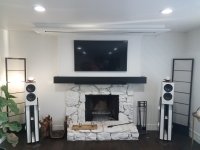
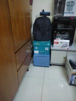
In my "home cinema enhanced" living room have an Atmos 4.2.4 setup (2 subs, phantom center) with the front speakers as pictured and a motorized tension screen (92in) dropping down in-between them.
I found using the phantom center gives me much better sound than any of the center speakers I had ever used in the past since they are never optimally placed and not matching the fronts in construction in a typical living room.
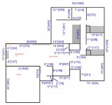
The room itself is a pretty open space (41ft x 14ft x 8ft) and has crawlspace underneath and attic on top so I hardly have problems with room modes.

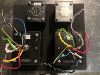
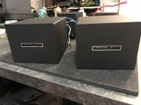
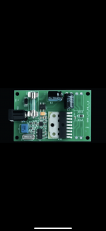
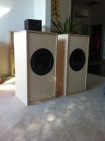
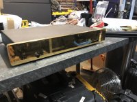
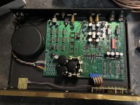
The front speakers are a custom 3-way active construction consisting of
- Vifa XT25 tweeters in waveguide and SB acoustics 6.5in midrange woofer in a very heavy built top cabinet
- 4x Peerless SLS263 10in woofers in a Ripole (dipole bass) configuration built into the stands
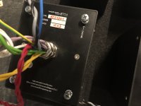
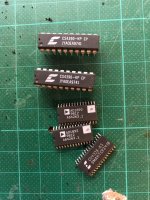
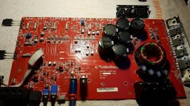
- 4x TPA3116 amps (50W per) built in
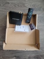
- miniDSP HD 2x4 for crossover and room correction

Now I'm very happy with how these sound and both the HF waveguide and the dipole bass create a very pleasing sound field with tight bass also very got off axis frequency response.
But in movies unfortunately I can easily get the woofers to reach their limit at scenes with a lot of LF content due to the rather inefficient dipole construction.
So I thought what improvements I could make with also remodeling the front of the room.
And after all movie viewing is maybe 90% of my listening and I could revisit a very "musical" dipole speaker later down the road if my habits change or with a dedicated listening room.

The goals:
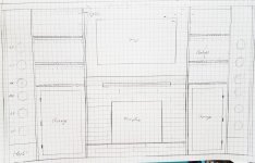
  • bigger movie screen (120-130in) for more immersive experience
  • better SPL for LF content (more powerful subs)
  • storage (cabinets and floating shelves incl. indirect lighting) around the fireplace

The obvious answer would of course be: Move everything into the corners.
Now that's usually a bad idea but if I can do this as a built-in solution (think soffit mounted speakers or baffle wall) I can avoid some of the pitfalls and have many advantages to traditional placement (no baffle step, no SBIR, using the walls as "waveguides", etc.).
I was thinking of something akin to William Cowan's approach for "Unity, The Finale" which seems to have worked well but with an additional curved "false" or decoupled baffle for aesthetic reasons.

The plan:
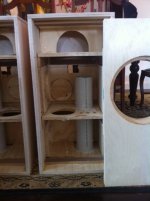
Keeping the HF and MF section the same cabinet just integrated into the corner I would focus mainly on the LF or subwoofer replacement. A built-in solution would have to be pretty compact and while there are other approaches like infinite baffle subs in the ceiling or crawlspace I would rather avoid additional vents in the ceiling or cutting holes into my hardwood floors and after all WAF plays a huge factor always in living room environments.
Plus I would like to re-use the existing components and avoid bigger expenses other than wood.

TLDR: I was evaluating different subwoofer types in the context of corner placement in roughly 200l volume each and basically narrowed it down to two preferences: 4-8 sealed subs vs. 4 transmission line designs.
I also simulated a regular ported design but it seems to offer no advantages to the upper two.

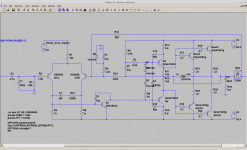
So I went into WinISD and also tried out the excellent TLine program (Leonard Audio?) to simulate my options. Have never attempted Hornresp so far unfortuantely. And in another first I played around with SketchUp to model up a possible TL design, the sealed speakers are straight forward I would say.
Here a few comments from my perspective, feel free to take these half educated assumptions apart. I'm a German so I can take direct criticism 😉

Sealed design:
  • lower LF performance
  • lower physical volume (say around 80l per 2 woofers) - remaining corner cavities could be damped with rockwool
  • all drawbacks of sealed design (unwanted resonances, high loading of the driver, big impedance peak, etc.)
  • easiest constructions but probably very stiff cabinet needed

Tapered TL design (200sqin to 24sqin):
  • better LF performance (although damped and with my volume it nears IB or ported sub behavior)
  • effective use of back wave, lower impedance peak and excursion (above 20Hz)
  • more complex construction but maybe fun (I love woodworking)

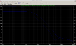
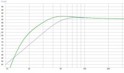
As you can see from the screenshots the limited TL design I could fit into each of the 4 front corners looks good and offers around 6-8dB more LF volume vs. the sealed simulation but higher delay and some phase "funkyness" between 20 and 30Hz, both of which I doubt I would notice much.
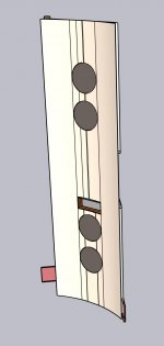
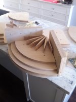
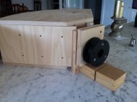
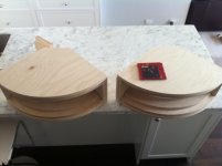
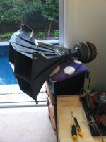
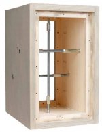
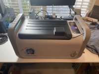
3D model:
Please excuse the otherwise still crude sketchup model, I'm still learning this new software.
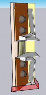
And the folding I chose was with easy wood cuts (not too crazy angles) in mind but could of course be adapted. The sections from the TLine simulation also attached. I noticed stuffing moderately and predominantly in the long sections helps more with a good FR than the rule of thumb of heavy stuffing in the initial section and little to no stuffing at the end but maybe the simulation is not fully accurate here.
The idea with the last section running through the first is optimizing the overall length, coming out the front close to the woofer and that section then also doubling as bracing.
The overall height is 90in and the very top would receive a dedicated cover and above it is the slightly dropped ceiling for the movie screen.
The second port as well as the HF/MF cabinet are not modeled yet and will follow. I plan to stuff all the voids, especially around the HF/MF section with rockwool or similar.

A few questions remain though apart form the general "is this a stupid idea":
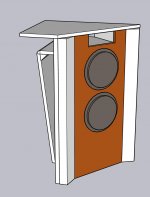
  • Is the terminus location on the front baffle close to the woofers good or bad? It should be roughly in phase with the main signal so I would say it doesn't hurt but have sometimes read otherwise in this forum
  • How strong would the vibrations be to the structure of the house since I plan on using two walls and the floor as replacements for actual cabinet walls?
  • I'm worried the additional 6dB per sub for the corner loading and 12dB for the 4 subs playing in phase would maybe overpower the LF end and lead to too much gain in the 20-100Hz region? In which case the slope of the sealed approach might be enough to get good enough 20Hz SPL?
  • Room modes are not really an issue so far but with the design being completely unflexible am I building myself into a corner (pun intended) that I can't get out of? I can do a lot with equalization with the two miniDSPs though.
  • I'm slightly worried about the front soundstage moving further apart and the resulting stereo imaging and phantom center although the HF waveguide and the rounded baffle will help a lot I think.
  • I could forego the curved baffle for a straight and gain a little more room but it doesn't do much for the FR or SPL.
  • Do I couple very rigid to the room's walls (i.e. glued and bolted) or preferably less permanent and somewhat vibration damping, i.e. bolted but with neoprene in-between?

So let me know what you guys think... should I give it a try, there would be no going back if I do unless I manage to make a standalone prototype that I could measure free air before I put it into the corner. But either way I'd have to take at least one floor stander irreversibly apart.

Attachments

  • floorplan.jpg
    floorplan.jpg
    238.5 KB · Views: 484
  • 20210217_165453.jpg
    20210217_165453.jpg
    460.2 KB · Views: 447
  • 20210217_163230.jpg
    20210217_163230.jpg
    407.8 KB · Views: 438
  • seal_port_SPL.JPG
    seal_port_SPL.JPG
    54.9 KB · Views: 348
  • TL_SPL.JPG
    TL_SPL.JPG
    60 KB · Views: 349
  • TL_enclosure.JPG
    TL_enclosure.JPG
    44.6 KB · Views: 218
  • 3D_TL_baffle.jpg
    3D_TL_baffle.jpg
    55.7 KB · Views: 263
  • 3D_TL_dual.jpg
    3D_TL_dual.jpg
    76.2 KB · Views: 262
  • 3D_TL_standalone.jpg
    3D_TL_standalone.jpg
    62.8 KB · Views: 287

FS : MoFo amplifier

As per title, I have my MoFo amplifier for sale

Unfortunately, my speakers are not efficient enough to take full advantage of this amplifier. It was a fun project though.

Chassis is custom design and looking retro. It is a dual mono construction in a single chassis. Coupling caps are Mundorf Supreme, resistors are Takman and Dale. SMPS bricks are included (different shapes but same ratings and both from Lenovo.

MoFo SOLD$USD plus shipping + 4% Paypal.

How about SOLD$USD for both Amp and preamp + shipping... Holiday combo special SOLD$USD +3% PayPal +shipping (preamp and amp)

Preamp alone is now available for grab @ SOLD$USD +shipping

Not responsible for import fees, duties, taxes, etc...


2021-12-06 22.16.45.jpg

2021-12-06 22.16.48.jpg

2021-12-06 22.17.05.jpg
  • Like
Reactions: FullRangeMan

Mixing High Quality capacitor brands?

Here I am making the bedroom speakers again and using the series crossover designed by rabbitz for the 2-Way reference thread.
rabbitz has kindly gifted me some parts and amongst them is a pair of Mundorf supremes in 3.3uF; I need 6.8uF [ or possibly 7.2] for this XO. It seems a shame to waste the gifted caps by not using them [ Thanx Peter] but I need to parallel caps to get the correct value. I'm trying to determine whether or not to put in an order for a pair of matching caps in either 3.3uF or 3.9uF and try for something closer to perfection or to simply use a couple of the Jantzen blue I already have.
I'll start another build thread for these as soon as I have some table space to start cutting out panels but 2.5 way using Vifa P-13 + Vifa D-27-45-06 and a Dayton DC160-8 for the point five

External crossover query

Perhaps this is a question I shouldn't need to ask but how much influence does a metal case have on an external crossover?
I've made a coupe of stand alone external XOs using old amplifier cases [ to make use of the speaker terminals for outputs ] and I could hear no different to my naked crossover patchworks.
Putting the XO outside one of the pairs of boxes I am modifying at the moment would make things a bit easier for me and I have several old amplifier cases sitting around and access to free or very cheap old computer towers, although the old computer towers are pretty big
EDIT
"Just in case" I don't mount any XO components directly to the steel of the old case; I use ply or thin MDF, I use the old case to provide impact and sticky finger protection for the components and I stand off with 20mm timber battens

Automation / Integration between Parametric CAD and Hornresp - Volunteers request.

Hello,

Many colleagues here in the forum already use CAD software to draw your Loundspeaker projects, some also use it to support their analysis in order to get input data to hornresp, and other prefer to uses the Microsoft Spreadsheets created by Brian Steele, for sure there are other options out there, but except the Spreadsheets that is freely available, probably all the other the users didn't share their tools and even if they share the major part probably is using payed software witch can reduce the accessibility. In this contex,t I decide to move from Solidword to FreeCAD and to share with you the CAD files containing Loundspeaker 3D model, fully integrated with parametric sketch which include and embedded Spreadsheet that you can be used as inputdata for Hornresp simulation and if you want/need further automation, you can use the macro to export Hornresp *.TXT inputdata.

Attached you can find a presentation about how to use it. The idea was to make it simple to use and freely available to everyone.

It would be very welcome and appreciated if you guys could test this tool and and provide feedback to improve it.

If anyone like the tool and want to make it available trough any wibesite. please do it, currently there is two models available, but it would be very fast to generate all Spreeadsheet models. Tapered fold are the most time consuming ones due to related constrains.

Check FreeCAD in the link below, available for Linux / Windows / Mac.

https://www.freecadweb.org

Attachments

  • Like
Reactions: Audiodidakt

How to improve this 5532 mic pre-amp schematic

Hi All,
If you are not interested on reading long posts, then simply jump to Actual Question section below.
I'm new to this forum.

Story and motivation​

=============

Last weeks did some play with pc line-in, and just connected my mobile phone to PC's line in with an AUX cable. when did play music on mobile and heared it from headphone, i just thought it is ultra clear sound for me! currently my PC is very old, probably my case cost about $20-$30 overally, but the onboard line-in does a good job at 24bit, 48KHz sampling. So decided to create a mic and preamp instead on Buying one. so bought several electret mic, which seller told me they have reasonably good quality for the cost:
mic.png

I would like to use two of electret microphones (triple wire electret mic) and through a pream, feed it into line in of my PC. Was not able to find appropriated preamp schematic specially for this purpose.
The reason i'm doing this is line in of my PC have a pretty good quality as I've said (24bit 46KHz) but mic-in had terrible noises.

When directly connect mic to my line in, then (as expected) there is high noise with a little non-noise sound 🙂
All i understand from searches is to need to amplify the mic-level to line-level, which approximately need 1000x amplification (+60 db of gain). After hours of searching i've seen several preamps which is tested and seems working good: Login to view embedded media There is also another one which is 1000x gain amplifier is three 10x stages: https://sound-au.com/project158.htm

So based on those two preamps, did designed some schematics for new 1000x gain preamp. Which mixes two electret mic output and convert to the line-level signal. which you can see below:

Also note that i'm newbie in the electronic field, more i'm a progammer guy instead of electronic one.

Current Scehamtic​

============

Consider this schematic. It have two electret mic input, after 10x amplify of each one, mixes them into one signal, and through another two 10x stages, the final result is ready. total gain is about 1000x which i think is quite good for converting mic level to line level.

Microphone: there are two electret mics (each have 3 pins). i do feed a 1.5V AA battery bias to it and feed the output of mic to the schematic below

Stage 1: There are two mic signal, which have about 500mv DC offset. amplify it with 10x the (I know 500mv ofset also amplified), then use 2 caps to remove dc from signal, and then simply mix the both signals with shorting them together.
stage1.png

Stage 2 & 3: output of stage 1, is 10x amplified. stage 2 and 3 also each one 10x amplify the result and finally I think there should be 1000x gain 🙂

Stage2and3.png


Actual Question​

==========

What do you think about this preamp? Does it work the way i expected? do you see any specific points which it will fail? I would be thank full for your opinions.
Because I'm newbie to this area, I need your talented guys's opinion about this schematic. Then i'll start to make and test it

Link to full schematic:
https://oshwlab.com/epsi1on/5532-preamp

Threshold FET 10HL with e/STASIS topology upgrade

I recently purchased a used Threshold FET 10HL preamp, it has a sticker on the top panel indicating it has been factory upgraded to e/STASIS topology. I assume this upgrade was performed by Threshold in Houston, TX, after Nelson Pass left long ago to start PASS LABS. The preamp did not have a power supply with it, however, I have an E power supply for my FET 10Pe phono stage.

The problem I have is the HL uses a circular power connector for the umbilical cable from power supply to preamp, and the Pe phono has the umbilical cable hard wired to the phono section and a Tajima 3 pin connector to the power supply. I need the 8mm 3 pin female connector for the HL section, does anyone know who the manufacturer/supplier is for the connector?

IMG_2568.JPG

Attachments

  • IMG_2564.JPG
    IMG_2564.JPG
    511.1 KB · Views: 245
  • IMG_2567.JPG
    IMG_2567.JPG
    302.5 KB · Views: 237
  • IMG_2569.JPG
    IMG_2569.JPG
    316.9 KB · Views: 250

Visaton W 300 S

Morning lads,

anyone has experience with this driver? Looks like a good candidate for a compact ported. Plan to build a set of high output 3-ways to use in a room which would be for recreation and playing guitars (loudly) either through a 50W ENGL tube head (driving 2 x 12 Marshall Celestion V30s) or through a high tier processor directly into the audio system. Also considering the Peerless SLS 12" (would be used sealed) and the BMS 15S430.

Ian Canada FifoPi/transport issues.

Apologies for resurrecting an old discussion regarding the pop / switch noise present when starting tracks on Ian Canada’s FiFoPi Transport combination. This seems peculiar to Ian’s products and doesn’t occour on either of my two HiFiBerry pro transports or my Allo Digi One set ups. (All powered by custom built power supplies not the RPi supply).

The noise is highly annoying and really unacceptable on what is my most expensive, best sounding but frustrating transport by far. DAC ranges from Arcam D33, Audiolab M-DAC to Arcam Black Box 1 and Marantz CDA 94 and the pop is present on all of them regardless of what input (optical or wired I use).

Ian’s transport is powered separately to the RPi fed from an SMPS feeding 5v to the Raspberry Pi and a 12v supply to dual 5v regulators to the FIFO/Transport set up.

The old thread I found quickly moved off topic. Did anyone ever get to the bottom of this? If it was resolved please would you share what the solution is?

Kind regards
Brian

Orion 2100 HCCA Needs NDP7060s

I’m trying to repair an Orion HCCA 2100. Upon removing the clamp bars I found several blown NDP7060. Digi-key says that model is discontinued and they don’t have any replacement models that match the amp and voltage ratings of the NDP7020s (60V/75A). So I’m looking for a replacement rated for 60V or higher and 75A or higher.

FQP85N06 is 60V and 85A so I’m tempted to go that route. But are there any other specs (other than physical sizes) that I need to match up? Am I sacrificing in other areas by increasing the amperage capacity of the transistors or is this just a more robust model?

Attachments

  • 2DB76091-6878-4056-B592-0651575C4267.jpeg
    2DB76091-6878-4056-B592-0651575C4267.jpeg
    385.3 KB · Views: 194
  • F864533C-9D39-407D-9F89-8600292D55A7.jpeg
    F864533C-9D39-407D-9F89-8600292D55A7.jpeg
    586.5 KB · Views: 168

Please critique my PSU

G'day Guys,

I've been brewing up a PSU board to use for a Rod Elliot P3A that I have in the works.

The idea here is to have something simple, robust and modular such that it can be used for other projects in the future.
I would be ordering with 2oz copper.
I've put in plenty of extra pads to account for parts substitutions eg; different sized film caps, resistors, screw terminals instead of spade connectors etc
By my maths I need 3 +/- connections ( 1 for each amp board and 1 for speaker protection) and 6 grounds; 2 for amp boards, 2 for speaker ground return, 1 for speaker protection and 1 for the chassis earth.


PSU schematic.png

PSU top side.png

PSU bottom side.png

Any criticisms or feedback?

Is anything I have done here simply daft?

Am I good to go?

Many Thanks
Sadface
  • Like
Reactions: sumeshak

Scott PS 48A 1 Turntable no sound.

Hi.
Just looking for advice to trouble shoot my Scott PS 48A 1 Turntable.
I am getting no sound being amplified.
The turntable fires up, the platter turns either on either 45 or 33, the pitch function adjusts well but no sound is being amplified.
If I place my ear near the cartridge I can hear sound coming from the stylus to record contact.
Amp being used is Marantz PM6A using MM RCA connections.
Speakers work via TV/AUX.
Alternate turntable works via the same MM RCA connections.

How should I go about identifying or locating the problem?
cheers Cliff

FS: Russian PIO Capacitors

Cleaning out my Russian Paper in Oil capacitor stock:
These are all (lightly) used in crossovers

6x K75-10 250 V 0,47uF
2x K75-10B 250 V 1uF
3x K75-25 250V 2.2uF
14x K75-10 250V 2.2uF
2x K75-10 500V 1uF
2x K75-10 500V 1.5uF
24x K75-10 500V 2.2uF
4x K75-10 500V 3.3uF
4x K75-10B 500V 10uF
6x MBGT 1000V 10uF

Will ship worldwide
Asking 180€

Attachments

  • tempImage0o3Byk.gif
    tempImage0o3Byk.gif
    1.5 MB · Views: 426

Pics DIY Yuichi 290Hz Wood Horn

Have started a new system build featuring:

Yuichi 290Hz wood horn with massive Altec 288 drivers
Mid bass in sealed cab, driver to be decided
Lab12 sub
MiniDSP for sub, passive for horn
Custom new 6 channel amp from Holton Precision Audio (Tasmania).

High End Audio MOSFET Amplifiers - Amplifier Modules - DIY Amp Modules - DIY Audio - Amp Kit

Exciting.

Using lovely Euro birch ply in mix of 18 and 24mm.

CNC'd design Yuichi for easy cutting and assembly.

Temporary use of Altec 8005 multi cell horn...which sounds wonderful.

Attachments

  • dry run.jpg
    dry run.jpg
    55.5 KB · Views: 3,628
  • rear view adapter.jpg
    rear view adapter.jpg
    92.5 KB · Views: 3,492
  • top view.jpg
    top view.jpg
    78.8 KB · Views: 3,433
  • port in place.jpg
    port in place.jpg
    62.2 KB · Views: 3,362
  • finished pair.jpg
    finished pair.jpg
    56.1 KB · Views: 3,378
  • Altec 1005 multi cell 2.jpg
    Altec 1005 multi cell 2.jpg
    68 KB · Views: 1,403
  • Like
Reactions: behappybevegan

Sansui AU-20000 DC on Speaker output no audio

HI Folks, I have a Sansui AU-20000 that has a 1.4V DC voltage on both speaker outputs. There is not audio output from either channel. The preamplifier section runs perfectly fine (I can connect to an external amplifier and it plays well). I have tested all the Power transistors and they all look good. I cannot find anything wrong with the audio boards too. Do you have any tips / suggestions on what can be done to resolve this issue? I'd like to get this unit working again. Regards Wala.

Audio note kit l3 phono

Hello everyone, I bought some pcb to build a phono of audio note kit, I assembled everything tested and it is here with me that it sounds great, I have only a small problem, at the volume setting of my pre I hear a hum, which goes increasing with the volume, I used shielded cables, and separate transformer for the filaments.I use a gyrator instead of the inductor. I am attaching the schematic so that I can comment better.

Attachments

  • l3phono.png
    l3phono.png
    95 KB · Views: 1,466
  • gyrator.png
    gyrator.png
    18.7 KB · Views: 1,288
  • M2PSU_Schematic_260_12.jpg
    M2PSU_Schematic_260_12.jpg
    149 KB · Views: 1,884

Infigo Audio Class A?

There was an amplifier on demo at the recent AXPONA which I found interesting and maybe so to forum members. A monoblock pair of amps from Infigo Audio was driving a pair of Alta Alec (edit: Adam) speakers. The amps looked wonderful and this system sounded great (really nice speakers!), but what most interested me was the amps are said to be pure Class A and rated at 250W into 4 ohms. The heatsinks were cool to the touch, though, so I asked the rep if they're modulating output voltage. I was told the rail voltage is held constant, which implies they could instead be doing some new twist on an active current source like the Aleph series amps. Except they're claiming a lot more power and producing way less heat than the Aleph amps.

Anybody have an idea what could be going on with this amp? (I also would have guessed maybe $10-20k for the pair, yet they're priced at $50k! The entire ultra high end has jumped the shark on top tier pricing. It was nice to see so many new companies putting out products, though. Many new names to me, quite a few of them coming from Europe.)

https://infigoaudio.com/page/method-3/

Xing U30 USB + Hqplayer + DAC dsc2

I am using for a long time hqplayer with dac dsc2 and with amanero DDC. With great sound and satisfaction.

A short time ago I bought the Xing U30 DDC to replace the amanero, and it works very well, only some small problem like having to unmute in the xing application every time I open hqplayer or change the playback resolution, i hope that this is solved in future firmwares.

This ddc (Xing U30) brings more and better internal voltage regulators, the question I ask you is, is it worth feeding 5v clean external and separately from usb? In the amanero I always did, in this I think it is not worth it, but I would like to know your opinions, people who have worked with the same components.

For power supplies clean external of 5V will use Salas ubib 1.3.

Attachments

  • 1665569709804.jpg
    1665569709804.jpg
    392.1 KB · Views: 475

Enlightened Audio Design DSP7000 dac chase

Cleaning my shelves I found an EAD dsp7000 dac, with quite mangled interior...
No dac chips, no receiver or filter chips. Opamps are present, transformer, power supply
Nice gold front panel
No idea if it's still working...

Could be a nice enclosure for a diy dac, or if somebody wants to take on the task of restoring it...

20€ and shipping

Attachments

  • IMG_2994.jpeg
    IMG_2994.jpeg
    423.9 KB · Views: 138
  • IMG_2996.jpeg
    IMG_2996.jpeg
    606.7 KB · Views: 154

Electrocompaniet 2 channel audio preamp - no output

Hi All,
I recently partially re capped my 'Electro' preamp, but since then - it will not give any output once the relay clicks in. Its this one, which is the one with the Electro Power amp and the two supplies.
On turning on the power amp, there is a low volume scratchy output on the L channel, then a fizz noise, then nothing. The output relay clicks in no problem. I checked the output transistors - they're Ok, so am now going through the transistors on the little amp boards - but if anyone has any suggestions I'm all ears.
I've checked the amp operation with another earlier preamp and all is fine.
Many thanks in advance
Joe

Attachments

  • IMG_2003.JPG
    IMG_2003.JPG
    582.4 KB · Views: 157

Lines transformers as output transformers

Hi all,

Quite a few years ago there was a webpage by Paul Cambie and aslo Grant Wills which detailed the steps involved in determining if PA line transformers could be used as output transformers in valve amps.

The webpage by Paul Cambie went into great detail, As an untrained tech myself, Pauls webpage set out the details in tables that was very easy to understand.

Both of these webpages no longer exist, I know there's links on Oz Valve amps site with some information but it doesn't go into detail like the original page did.

I'm wondering if anyone has kept a copy his webpage that you could post a copy here, I thought I had printed it off at the time. I have two line output transformer that I'm trying to work out if I can use them.

I've found one video on youtube which isn't very helpful and there are a few threads here eluding to this information but nothing which details the steps as the original webpage by Paul Cambie had done.

cheers if anyone has this information. they could post.
  • Like
Reactions: dufflecoat

DIY 2-Way Bluetooth Speaker with Sub for a Tuk Tuk (Rickshaw)

So this week I took delivery of a lovely Bajaj RE4 Tuk Tuk, https://a2zvehicle.com/bajaj-auto-rickshaw-price-list/ and I'd like to add a stereo to it. My first thought is to buy a cheap bluetooth amp like this one:
ebay and hook it up to some speakers.

Now it just so happens I have a pair of Mackie CR3s, Mackies which have a faulty amp, so I was wondering if it is possible to repurpose them some how. Maybe build a box for the rear parcel shelf and fit them into that. I also have an old Eltax sub speaker driver, like this one Sub

So for a bit of fun if I could add that to deal with the bottom end that might be cool.

I'm wondering if that little amp will be capable of running the Mackie 2 ways mids and tweeters, and at the same time the eltax sub.

What I have no idea about is creating the crossovers, and also how I can run the single sub from the stereo feed of the amp. Presumably I need to split the signal somewhere?

I'm not looking for sonic fidelity here, it just needs to be something cheap and cheerful which can put out a little bit of bass!

Tame down buzzing caused by low bass notes 😅

Another 4th order subwoofer installed on my new gaming Desktop recently ... This subwoofer has 2 down firing ports and it uses 1 unit of homepod 4.5inch woofer unit ... The woofer does goes very low in this setup BUT the cabinet (to the left) and the computer unit were suffering from serious rattling and buzzing caused by those bass notes which can be annoying at times ... Any solution to go around this? Thanks

Attachments

  • IMG_20221013_212008.jpg
    IMG_20221013_212008.jpg
    247.2 KB · Views: 134
  • IMG_20221009_184817.jpg
    IMG_20221009_184817.jpg
    248.5 KB · Views: 135
  • IMG_20221013_212034.jpg
    IMG_20221013_212034.jpg
    341.4 KB · Views: 138
  • IMG_20221009_102644.jpg
    IMG_20221009_102644.jpg
    327.4 KB · Views: 130

Denon DRA-1024RA repair

Hi,

Got a Denon DRA-1025RA on the bench. It plays, but since I got it I noticed that the stereo separation is lousy. It has a "mono" button and "Simulated stereo" which I thought may be the problem, but noticed that the bass control does not work at all.

Disassembled it to find the bass control is physically broken. The nut that holds it to the chassis was not tight and I guess over the years it snapped guts.

VR402, part number stamped on it is 2110536006, and 30KCX2.

Service manual has an additional number of V1620V30FC303K with a description of 30Kohms BASS.

Any idea where I can find a replacement?

For now, I may just put two (well, four) 15K fixed resistors in there to simulate being in the center of the range.

Thanks!

Parts list for Quad ESL 63 EHT board

Hi Everyone,

I recently traded for a pair of Quad ESL 63's (US studio version). The problem one is currently having is that it's playing back at reduced volume, no pops, hiss, crackles, or distortion, just reduced volume. (the neon bulb isn't flashing every second, I only get a flash when I first turn it on) After thumbing through the service manual it seems like it's probably the EHT board. I would like to rebuild it with slightly beefier components and I was wondering if I could get some suggestions from those who are more familiar with the 63's.

I know you can buy pre-done boards but, where's the fun in that? (and I'm a little on the broke side at the moment 😛 :-D )

According to the service manual the Caps are 10nf -20 +50% at 2KV
would moving up to a higher voltage rating be worth the extra money, and perhaps switching to metalized polypropylene?

The diodes are 1AV30's these are the specs I was able to find online for them:
I(O) Max.(A) Output Current 10m
V(RRM)(V) Rep.Pk.Rev. Voltage 3.0k
t(rr) Max.(s) Rev.Rec. Time 300n
@I(F) (A) (Test Condition)
@I(R) (A) (Test Condition)
V(FM) Max.(V) Forward Voltage 15
@I(FM) (A) (Test Condition) 10m
@V(RM) (V) (Test Condition)
I(RM) Max.(A) Reverse Current 2.0u
@V(R) (V)(Test Condition) 3.0k
I(RM) Max.(A) Pk. Rev. Current 5.0u
@V(R) (V) (Test Condition)
@Temp. (øC) (Test Condition) 75õ
Semiconductor Material Silicon
Maximum Operating Temp (øC) 80’

Would a GP02-30-E3/73GICT-ND work as a replacement?

And should I change any of the resistors on the EHT board? and if so do you know what wattage I should get, I didn't see it mentioned in the service manual.

Thanks

Rockford P6002 output FET measurements

Hi guys,

So, working on my first P6002.
The amp has some trouble with the output fet/ drive circuit. I'm a bit confused by the measurements.

I removed all the output cards/fets, and the amp powers up just fine.
In case of the output fets removed and +-41v rail voltage, there is approximatelly +28v and -28v on the gate of the output fets.
When driving a 40Hz sine wave into the RCA's, there comes a very clean square wave signal on all the output fets gates, with a DC voltage of the above +28v or -28v (high side and low side banks)

When soldering in new fets (1 per bank), the +28v and -28v on the high/low side gates changes into positive or negative rail on the output fets gates.
No square wave signal present anymore on the output fets gates, and full negative rail on the speaker terminal.

I don't get it. This should be a class AB amp right?

Attachments

  • PHOTO_20220427_210854.jpg
    PHOTO_20220427_210854.jpg
    556.9 KB · Views: 114

Philips CD560 Capacitor Mix Up

I have two Magnavox CDB560 (Philips CD560) decks that I am recapping. My first foray into such a project, and I am a newbie on the Forum.

These decks are one step below the CD650 in this product line's lineup. I've compared the schematics for the 560 and the 650 and the main boards are almost identical for electrolytic capacitor values and locations, except for about 3 locations. The other big difference is the CD560 has LM833 Op Amps while the CD650 has NE5232N Op Amps.

Two capacitors mounted on the boards do not agree with the schematic. The Philips CD560 service manual schematic has Caps 2305 and 2309 as 1uF and 2.2uF respectively (Decoding 1 diagram). However, these are reversed on both 560 boards, i.e., 2305 is the 2.2uF and 2309 is the 1uF. I checked the service manual for the 650, and that schematic agrees with the 560 service manual schematic. One 560 deck was manufactured in January 1987, and the other in June 1987, so it seems that Philips kept building them with the capacitors reversed vs. the published schematics.

I have no idea which is correct, the actual manufactured boards or the schematics. So I have two questions I hope someone knows and would be kind enough to answer. Which is correct, as manufactured or as published? And does it make any difference if they are reversed?

For Sale Kirmuss ultrasonic record cleaner

Hello
I’m selling a very lightly used Kirmuss system.
Asking$675 shipped conus.
Contact me for more details if interested
It’s literally like new.
Thanks for looking and have a great day.

Attachments

  • 54A8789C-267F-476E-B2EC-19A8094CC0DB.jpeg
    54A8789C-267F-476E-B2EC-19A8094CC0DB.jpeg
    294.5 KB · Views: 131
  • 26E6A51E-6069-459B-A089-434A60E1884A.jpeg
    26E6A51E-6069-459B-A089-434A60E1884A.jpeg
    659.4 KB · Views: 120
  • 7D83E6AA-80AB-4AC3-8090-E7AD43FC8D9B.jpeg
    7D83E6AA-80AB-4AC3-8090-E7AD43FC8D9B.jpeg
    390.5 KB · Views: 126
Projects by fanatics, for fanatics
Get answers and advice for everyone wanting to learn the art of audio.
Join the Community
507,663
Members
7,883,191
Messages

Filter

Forum Statistics

Threads
405,981
Messages
7,883,191
Members
507,663
Latest member
The driver