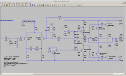
I have a Lafayette LR-9090 whose left channel drops out intermittently once it gets warm.
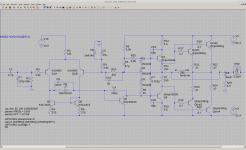
The power amp has an unusual feedback arrangement, so I tried it in Spice.
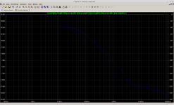
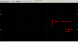
EEK: this thing is a power oscillator from the factory! Look at that loopgain plot. Maybe exact transistor choices are the difference between life and death for this thing, but it's living on the edge.
It looks like a 39p miller cap, and a 2p lead cap in parallel with the 330k NFB resistor, should tame it.
The power amp has an unusual feedback arrangement, so I tried it in Spice.
EEK: this thing is a power oscillator from the factory! Look at that loopgain plot. Maybe exact transistor choices are the difference between life and death for this thing, but it's living on the edge.
It looks like a 39p miller cap, and a 2p lead cap in parallel with the 330k NFB resistor, should tame it.
Attachments
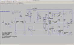
Mark, please ignore R15 and C7 in that schematic. Those are not on the factory schematic nor in the real circuit. I was playing with adding another pole and zero here and forgot to remove the elements. As you say the 1p/1000k values have near zero effect and don't change the basic story at all.
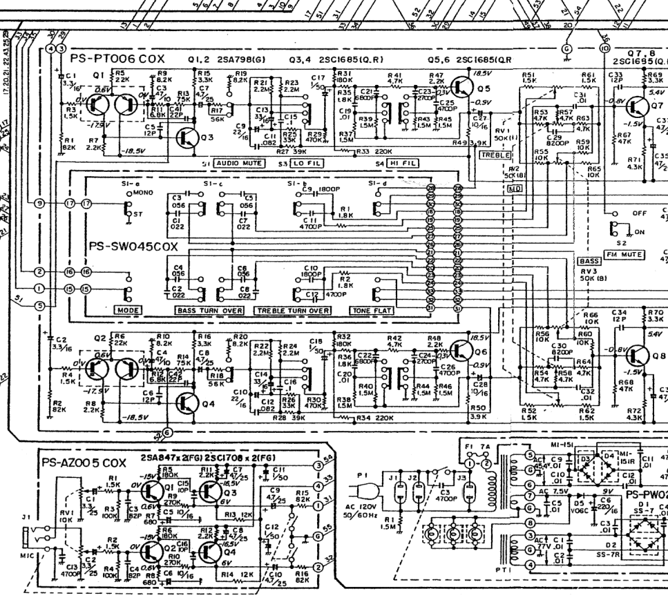
I found some diffs between the factory schematic and the real circuit. The weirdest thing about the factory schematic is the R31 feedback resistor, which takes feedback from outside of the output inductor -- defeating its purpose and ensuring the circuit will oscillate into even a small capacitive load. :/
On the real circuit, R31 is open and R10 is 47Kohm -- a bog standard feedback setup. This LR-9090 has an August 1980 date written on the power transformer, which would make it a late-production build so it probably reflects most or all changes that the factory made over the course of production.
I confirmed some other component values from the factory schematic match the real circuit: the miller cap really is only 15p, the tail resistors on the LTP really are 1K, C19 and C20 really are 56p.
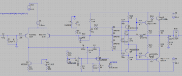
Here's an updated schematic that more closely matches the true circuit.
I found some diffs between the factory schematic and the real circuit. The weirdest thing about the factory schematic is the R31 feedback resistor, which takes feedback from outside of the output inductor -- defeating its purpose and ensuring the circuit will oscillate into even a small capacitive load. :/
On the real circuit, R31 is open and R10 is 47Kohm -- a bog standard feedback setup. This LR-9090 has an August 1980 date written on the power transformer, which would make it a late-production build so it probably reflects most or all changes that the factory made over the course of production.
I confirmed some other component values from the factory schematic match the real circuit: the miller cap really is only 15p, the tail resistors on the LTP really are 1K, C19 and C20 really are 56p.
Here's an updated schematic that more closely matches the true circuit.
Attachments
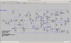
Here are the mods I did:
* Add a current mirror at Q5 and Q6. I built a tiny "daughterboard" for this on some spare perf board.
* Add the LED at D4 to lift Q5's collector above saturation. There's conveniently a jumper on the factory PCB where this LED can fit.
* Change the miller cap to 100p.
* Add the 2p lead cap in parallel with the NFB resistor. These were the only two holes I drilled.
The new circuit should be perfectly stable. It has about 36db of in-band loop gain, that's good for about -75db distortion performance. Not bad for a '70s "time machine."
The physical design of this receiver is a pain. You have to remove the outputs from their sockets, and then remove the heatsinks, to access the solder-side of the amp PCBs. You can't test what you've done until you get all that back together and it better work on the first go. The median amp of this era is more service-friendly.
Attachments
I wonder if the internal feedback path stabilizes things enough to allow sampling past the inductor with the other path? Presumably to push up the freq response at HF?I found some diffs between the factory schematic and the real circuit. The weirdest thing about the factory schematic is the R31 feedback resistor, which takes feedback from outside of the output inductor -- defeating its purpose and ensuring the circuit will oscillate into even a small capacitive load. :/
This old audiokarma thread about restoring a -9090 describes oscillation too:
Lafayette LR-9090 series / Setton RS 660 series Repairs & upgrades | Audiokarma Home Audio Stereo Discussion Forums
Lafayette LR-9090 series / Setton RS 660 series Repairs & upgrades | Audiokarma Home Audio Stereo Discussion Forums
Isn't 100p for a Miller cap a bit heavy-handed? What kind of slew rate does that get you? If my math isn't off, that should be about 6 V/µs.... bit on the low side, don't you think? This amp has enough power for a full-scale 20 kHz sine to reach at least 5 V/µs, leaving essentially no margin. Rules of thumb for advisable margin vary between a factor of 2, 3, 5 and even 10.
I'd try more like 47p and giving the input pair some degeneration instead (220 ohms maybe). Tail current is quite decent as-is.
A contemporary test for the presumably lesser RS440 model indicated some rather unusually high noise as well, so I had a look at the preamp.
OK, so it's got a 200k volume pot - oh well, not much you can do about that, but -40 dB is going to be ~2k, so not too tragic yet. 1k5 in series - well, if you insist.
The feedback side of the LTP though sees 8k2 || [6k8 + (75k || 82k)] ~= 7k, with the 82ks being R15/16 on the mic preamp board if you're wondering. This is because they are using the inverting side of the volume amp as an inverting mixer so they can mix in the mic. The things you do for karaoke. (That's a pretty sad excuse for a mic preamp, too, with a 10k level pot at the input and 1k5 in series, and an input transistor running at a measly 20 µA. Probably still less noisy than a modern-day Realtek mic input though.)
Total gain of the first stage comes out to +22.0 dB. With the power amp at +24 dB (stock), we're at +46 dB, minus a fraction of a dB loss, sounds about right - and that's it with TONE FLAT on. The relatively low power amp gain certainly doesn't make compensation any easier (more gain tends to allow for better slew rate).
Back to the volume amp input stage. We've got at least ~8k5 worth of thermal noise alone (~11.8 nV/√(Hz)), plus the volume pot. Then there is current noise. The input side transistor is running at ~300 µA, the other side at ~500 µA. Rather a bit hotter than needed, really - 100 µA should be plenty. And then they added 12 pF of Miller cap across the common emitter stage to compensate the whole shebang. I'd estimate input side current noise to be maybe 0.5 pA/√(Hz), so current noise would start to make itself felt above volumes settings of maybe -20 to -15 dB, eventually dominating around the worst-case -6 dB (= 50k +1k5).
Overall estimated output noise level at -40 dB comes out to maybe 360 µV. Which is 2-3 dB short of what would be considered average (a decently-done '4558 job with about the same amount of gain) but overall not terrible. You could do maybe 5 dB better if you insisted and tackled the circuitry, definitely noticeable but not night and day.
The RS-440 seems nearly identical in circuitry, I might even expect somewhat lower noise as the ferrite bead in series with the 13 V zener is replaced by a 100 ohm resistor. Ah, they noted that this receiver was "very touch sensitive". This might be a simple case of case panels not making good electrical contact and hence not being any good for shielding (happens when stuff is anodized or painted). Besides, it seems that this model also had a 3-pin IEC and connected signal ground to PE (potentially wreaking havoc on any test setup with equipment doing the same), quite unlike the Lafayette which has 1.5 megohms between cold and signal ground (a standard thing in the US, I think) and that's it. It could still be oscillation, but the power amp in the RS440 is entirely different and just connects 330k and 47k in parallel ahead of the Zobel.
Attachments
Last edited:
Isn't it 12V/usec slew rate? The LTP can source or sink up to 1.2mA into the miller cap, the same current passing through R3.
Emitter degeneration would be better for sure. It's perfectly stable to increase LTP current to 3mA, use 33 ohm degeneration resistors, and then a 68p miller cap. That increases slew rate and reduces distortion to around a -85db floor. Not bad at all for an old dog!
Emitter degeneration would be better for sure. It's perfectly stable to increase LTP current to 3mA, use 33 ohm degeneration resistors, and then a 68p miller cap. That increases slew rate and reduces distortion to around a -85db floor. Not bad at all for an old dog!
Thinking about it, you're probably right - I was only expecting half the tail current to be available.Isn't it 12V/usec slew rate? The LTP can source or sink up to 1.2mA into the miller cap, the same current passing through R3.
Whoops.Oh crap-- I added the LED in the wrong place, it needs to be inside the miller cap otherwise the LTP cannot sink current from the VAS and slew rate is extremely compromised. I am a dummy. So there will be another rev forthcoming.
I didn't really like the LED, but only thought about how well it would perform at the relatively modest VAS base current. I guess it's not that easy to include it in the LTP leg (above Q5)?
Last edited:
Adding a 33nF in parallel with the LED allows the input stage to pull 1.2mA out of the miller cap, and puts the slew rate back where it should be. I checked in sim and also with a rail-to-rail 20kHz sinewave on the real circuit with the scope.
Q2 is not a 2SC3503 (Cob = 3pF) it is the original 2SD381 (Cob = 25pF) for which I don't have a spice model. That's probably how the factory got away with only a 15pF miller cap-- it's paralleled with Q2's Cob for something approaching a decent value. Of course it's risky to rely on Cob as it's a poorly-controlled parameter, tisk tisk.
To slew negative, we must drain both the miller cap and Q2's Cob. Moving the LED inside of the miller cap loop wouldn't be enough: the only current available to drain Q2's Cob would be its base current.
This final arrangement lets the input stage drain both C4 and Q2's Cob.
You could use larger than 33nF, which would reduce voltage fluctuation at the input-stage tail during big slews. Don't use smaller.
Epilogue. The final circuit wasn't supposed to be interesting or have any nonstandard elements. The noteworthy item was supposed to be factory's malpractice. But here we are.
Attachments
Three years later...
I picked up another LR-9090 with two blown channels. I fixed this one a little differently, this amp circuit is good for better than -100dB distortion in sim. It features a current-limited VAS, and a CRD supplies constant current to the LTP.
From the factory, the NFB takeoff point suffers from poor physical design, it will pick up some half-wave rectified voltage. I rearranged things so that the NFB takeoff is downstream of where the PNP and NPN output rails meet.
The new one also doesn't have super generous slew rate, about 6V/usec. At a worst-case full-scale 20kHz, the TPC network draws about 1/3 of the VAS supply current. Again that could be improved with LTP emitter degeneration and lighter compensation.
Attachments
- Home
- Amplifiers
- Solid State
- Lafayette LR-9090: Factory-Built Power Oscillator