I received a Citation 17s that has a replacement volume potentiometer. I am trying to replace it with something closer to the original (since they were so proud of it). It is described as a "32-step, fixed-resistor attenuator". Listed as "Control Volume 22033996A" in the service manual.
Anybody help me with a model number?
Does anyone have an original that they can look at and give me more information? Is it an Alps or something exclusive?
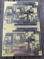
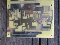
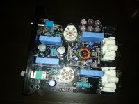
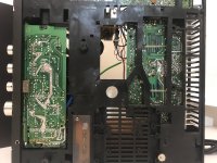
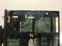
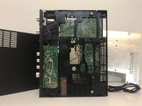
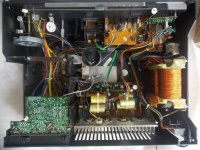
I found three pcb like these today in a second hand shop:
It writes "no feedback non inverting i/v" on it, symmetrical supply, power ground signal ground and 4 parallel pnp/npn transistors in the input can be identified, but other than that I'd need some help to figure out the original circuit's schematic.I might use it for an MCcart phono preamp adapter, but I hope to identify the original circuit if anyone can help me to.
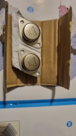
I had 8 6528A and 18 6528. I buy them just for OTL. but soon I found it not suitable. In Taiwan the weather is so hot . If i put it in my living room. It will be very terriable. So I want to make an AMP SE or SEPP will be fine. which tubes for 6528 seAMP will be better. I have 2 RAYTHEON 5842 some 5687 12av7 12b4a 6s4a 6c4 5844 5965 7898 6gk5 6er5 6j4 6j6 7062 ec86 6H30pi 6c45pi 5670 7b6 12sl7 12AT7 12au7....... or someone can give me an idea how to make a better SE-AMP.
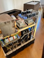
I have 2 of these monoblock power amps to sell and as I can barely lift them ( I’m pretty strong too ) they are for collection only .
Each one has a massive Drake transformer and sowter transformers .
The builder of them has deceased so I have no information on them other than that they are apparently 1000w .
I didn’t realise just how big and heavy they were until I arrived to collect them.
Perhaps one of you clever lot can make use of them .
Price is really a stab in the dark but I figured the transformers alone may be worth more than what I’m asking for .
At the same time I also collected what I believe is a lindsley hood designed amp which I may include with these .
I’m in Milton Keynes.
£200
Sold as spares or repairs as I dare not power them up .
never used, still in original packing. I took my system in a different direction, so I no longer need it. it's currently sold out at the diyaudiostore.
Hi ! I have a Accuphase pro-5 from a friend to repair, it uses 9 2SA1302 and 9 2SC3281 each channel, and i found one 2SA1302 and one 2SC3281 shorted in L channel, all the other are OK, and turned amplifier on and it works even without this 2 transistors, and my question is : what could cause that ? and if i replace only those 2 transistors and the capacitors in the board, should it be OK ? What else should i replace to make sure all is OK ?
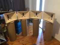
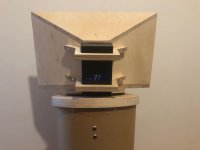
Here is cool speaker that I helped member Sirvalence with the design and he built them himself. He was too busy to post this but I thought folks might find this interesting.
A Beyma TPL-150 AMT tweeter is used in a straight wall expansion horn with some midbass injection provided by an SB Acoustics SB23NRXS45-8 woofer. The horn is about 52.5cm wide x 34cm tall at the mouth and 22cm deep (external dims) with a rectangular throat 25mm wide x 126mm tall. The angles are approximately 80 deg H x 30 deg V. The woofer fires through two 100mm x 23mm hotdog shaped ports located as close as possible to the throat such that the end of the port is about 35mm from the throat. The woofer is upfiring through the two ports and the backside rests on a large 30cm dia x 1m cardboard tubes which serves as both a stand and the bass chamber. The whole thing is active with a DSP crossover at about 1350Hz but sometimes plays them crossed low like a FAST at 550Hz. Yes, it is amazing that the TPL-150 can go that low. I think he uses basic TPA3116 Class D amps and runs these as a quadrophonic system.
Here was the foamcore pathfinder:
Then he made them in 18mm BB plywood.
Here are the four horns:
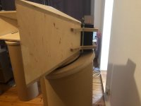
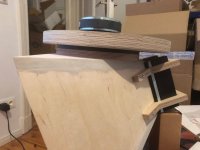
Side View Detail:
Rear View AMT mounting detail:
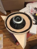
Woofer mounting plate detail:
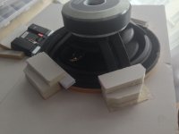
Adpater plate detail:
He says they sound great. Still playing with the DSP crossover settings and taking measurements to refine. We will try develop a passive XO for this at some point.
Hello guys.
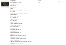
I wanna make an group buy of the componens pcb factory and assembly t for the AnalogIO x8 from https://github.com/freeDSP/freeDSPx-AnalogIO-x8 .
I can get on elecrow the pcb assembly and manufacturing (shipping costs to me and dutties for european union included) with price upto 8,97 usd (9€) each pcb. The pcb assembly is free with manufacturing.
The shipping costs to you is not included.
Note: If i can get interest for 40 Analog io x8 i can get an faster manufacturing and cheaper price 6,09 € (6,08 usd). For the same 40 and not so fast i can get 3,91 usd or 3,92€.
The component i can get from manufacturer and send to factory from supplier th3e price can be up to 68,73€ and if we can get interest for 40 boards i can get the components for 50€ aproximely.
All refered prices is refered with customs and shipping to me and manufacturer included.
Customs and shipping coststo your country are for your resposability.
I can get even more chep than i can get for 40 boards if i can get interest for more boards. 40 is only an example value.
I have been building a class D amplifier based off the wondom aa-ab32313 board for the L/R speakers and also AA-AB31315 board for the subwoofer. I have the input fed into a to a AA-AB41134 digital volume control, which is then split off into 2 paths. the first path goes into a AD828 preamplifier that amplifies the signal and then is sent to the first amplifier. The second path is where the signal is sent into the NE5532 subwoofer preamplifier/lowpass, and then sent directly to the 2nd amplifier. Both amplifiers use seperate 36v power supplies. However the first power supply also powers a LM2696 step down converter that steps down the 36v into 12v, and then powers both the stereo preamplifier and the subwoofer preamplifier. However, there is some ground loop noise and I'm not sure how to fix that. Do I use 3 separate isolated step down converters to power the volume board, and both preamplifiers separately or is there a more cheaper and easier solution?
I have a pair of B&O CX50 speakers. The woofer has been replaced with one of these The speakers have a great mid/hi, but the bass is very, very dull. Now I was wondering if adding bass reflex port would do it any good, and if so, what Fb to tune for to get a feel of some better lows?
The internal size of the cabinet is around 3,4 Liters. I was thinking about a 2,5cm bass port. I did some calculations using this spread sheet but I don't know if I'm off?
My experience with acoustics is very limited so any advice is highly appreciated before I start drilling holes in my old vintage speakers.
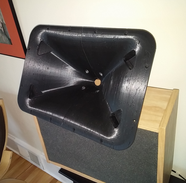
I’m finally done enough with the printed Unity type waveguide speaker design to post the files. This is a follow on to the thread "3D printing 1/2 of a waveguide". It seemed to make sense to start a new thread, as the first starts out just showing how the waveguide gets printed so it's not obvious there is a design beyond that. I'll post STL files for the printed waveguide, the crossover design, and details on the cabinet construction here. Feel free to comment, discuss, denigrate or even threadjack this.
I sort of doubt that many people will actually build this design even though I think it was a large success. But the build requires many steps in different skills. None of the steps are particularly difficult, but there are a lot of steps!
OK, that's not quite correct. Printing the waveguide is actually a somewhat difficult step, as it requires you to get hold of and configure a large-format 3D printer with a wide 1mm nozzle. Not to mention working through the learning curve of the 3D printer process. I consider myself still as not much beyond a beginner at 3D printing, it's a whole absorbing hobby in itself. You COULD send off the STL files to one of any number of 3D printing houses, though that probably wouldn't be cheap and you'd need to talk to the 3D printing people with specifics about how it needs to be done.
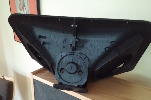
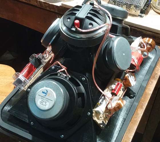
This is what the waveguide looks like after printing, then how it looks with all the drivers and crossover glommed onto it --
With all that stuff on it, the assembly can be treated like a single drop-in full range speaker driver.
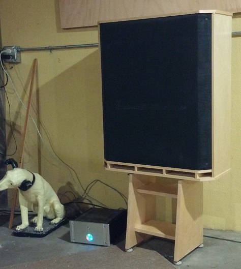
And here is a shot of a completed speaker, sitting on a simple stand I designed for it --
BTW, I had planned to put all these pix in the diyaudio.com gallery, but it no longer accepts new photos so these are being hosted from my own website.
Hello, just another BIAS adjustment question for any of the pro/experts here in solid-state Class A/B amplifiers.
Between an really old-school here and own 4 heavy-iron Samson amplifiers, the discontinued well built S line 1x S500, 1x S700 and 2x S2000 as I really like the warmth sounding of this units especially the S500.
I running fully active 3-way using 1x S2000 for the subs, 1x S700 for the mids and 1x S500 for highs.
So the main question here is if some expert in this topic can confirm if the VR101 POT in the S500 schematic picture is the BIAS adjustment or just the offset voltage adjustment, I will also attach the schematic diagrams of the Samson S line amps as all of them looks almost identical to me in regards topology/design.
P.S. I've recently recapped the PS of the S500/S700 units with 10,000uF 80v Elna caps but I was reading about BIAS re-adjust as well, though I have to measure them first but just want be sure about the VR101 POT, since I'm thinking on populate the disabled transistors on the S700 unit probably I will have to readjust the BIAS in that unit mainly.
When using this dac with my computer, differing levels of digital distortion were clearly present, with the best digital files having the least. The results were good to terrible.
But when I use my Carver MV5 cd player as a transport, I get much different and improved results.
Not only is the distortion reduced to a tolerable level, the sound is warmer and smoother, with a good soundstage and imaging, and with even more air than I am use to hearing from redbook digital.
I would also say that it is closer to analog than my old Micromega Stage 3
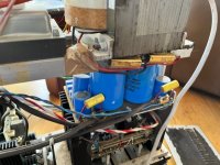
Following positive feedback from users, I bought a Reckhorn A-402 subwoofer amp earlier this year.
As soon as the amp arrived I plugged it in and noticed a significant amount of transformer humm. I decided to open the amp to see what could be done. The mains tranny is impressively large and it was easy to add some sticky feet to the exposed top so that it would be clamped into place when the base was replaced (this worked a treat - all audible hum disappeared).
While I had the case open I noticed that one of the six 10000uF caps had a swollen top. It also had a swollen base and some electrolyte had leaked onto the pcb. I removed the cap and it measured open circuit - I think the cap terminals must have been separated from the internal connections when the swelling forced the body of the cap up and away from the pcb. This was very fortunate, as no further damage had occurred as the cap was effectively disconnected.
When I first noticed the swollen cap I contacted Reckhorn and agreed with them that they would send me a replacement cap for me to fit (I bought the amp from Germany so it would have cost us both a lot of money to send it back and forward for repair). Reckhorn kindly sent me two replacement caps, and told me that they would have to remove caps from existing amps as they didn't have a stock of spares.
The replacement caps arrived last week and I decided to measure them both to select the best one to use. One of the caps measures 6640uF and the other measures only 4340uF. Both are NCC KMH 10000uF 100V caps!!!!!!!!!
I've reported this to Reckhorn and await their response.
Irrespective of their answer, I will probably replace all six 10000uF caps with better quality alternatives (probably costing me £120 plus a couple of hours work). I will not be happy using the amp while the KMH caps are still there.
I don't report this to the forum to have a go at Reckhorn - I am sure they have not deliberately used crap parts (and performance wise I'm very happy with the amp). I report this to warn other A-402 (and possibly A-401 & A-400...?) owners that they may have an issue to deal with.
Hopefully Reckhorn will respond to this problem in a professional manner - we will see....
I don't need any other sources and I have no need for EQ, so I thought I would skip the preamp and connect the dac directly to my power amp (Quad 303).
As I still need volume control I'm planning to add a tube amp stage with volume control after the cathode follower. The quad has a low input impedance (22kOhms) so I'm not sure which design would be best? My speakers are Quad ESL 57's.
Is this a good idea in general or am I missing something?
I've been designing ~450-500VDC linear power supplies on pcbs that also contain the rectifiers/filters for heater taps and switches. It occurred to me that layout should not be just about crosstalk/noise but also to avoid arcing or unintentional shorts. It looks like there is some general guidance from IPC-2221, but it is very restrictive.
You can see that for a 500VDC trace, you should have 2.5mm to 3mm spacing. That's quite a lot of spacing. Is this a practice that others here employ? What else can I do for safety on powersupplies?
Also, if anyone has found connecters with >2.5mm between the pins, that would be useful.
I’m looking for a simple (minimalistic) way to switch a 12 volt DC low current fan ON when a temperature of for example 30 degrees Celcius is reached. When the temperature drops below 30 degrees Celsius the fan should be switched OFF.
For this particular purpose the exact temperature is not too relevant, som deviation is allowed as well as some hysteresis.
A control for setting the ON temperature would be nice, but is not absolutely necessary.
Hello. It will be long story, so grab some coffee. I have been passionate audio lover since early age. I used to build some speakers, unfortunately, most of design went into choosing drivers and modeling the box. My last speakers with Peerless SDS 164 and Visaton DT94 was built maybe 15 years ago. I did not had much of experience with crossover design, so went easiest route. First order filters. I have decided to upgrade filters, but would like to get some help.
Unfortunately, if simulation and measurements of speaker before making changes to crossover correlated quite well, now correlation is gone.
Near field response, center of tweeter: https://photos.app.goo.gl/2BpapAb5KEFyodfM7
I would like to get some advices for designing crossover for these drivers. Stay first order? How to deal with hole around 2k? Any idea what could cause dip in 70Hz. It seems it is not caused by the room, because it is present in nearfield measurements.
I have a US Amps DE 1000 I acquired with blown power fets. It had been repaired previously by someone and I am unsure as to whether or not they used the correct fets (or if they where Ebay specials from China). The amp had IRF1010 fets in it when I opened it up. Is this the correct part number? The gate resistors are 47 ohm and the drivers appear to be operating correctly. I just need to know what the correct fets are to move foward with the repair. Thank you
Apparently, they sold their AV line to Sharp and Voxx... The name will continue but it'll probably be crap.
Bell and Howell used to make excellent projectors etc and now they are a name on cheap motion lights.
RCA used to make good parts and sets, now if I'm not mistaken, it's just a trademark of Thomson and now stands for Renowned Crap Association.
Hello all
If a ported box were to be built to size restrictions. E.g. 18L with 34hz tune. Can one such box be used to evaluate a number of different drivers?
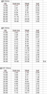
Hello, i decided to build a Gainclone amp for a pair of Markaudio CHN-50 since it can drive 4 ohms at 7 watts according to this table that i got from another post (attached below). As far as i have learn the power output depends on the power supply voltage and for 7 watts should be around 20-21 volts but i don't know how to calculate the power supply transformer specs, so i need to know:
1.- Is there a formula or procedure to calculate the power supply current or should i simulate the schematic?
2.- The transformer should be able to deliver more current than needed for safety? if so by how much?
3.- How to estimate the dimensions of the heat sink?
I hope you can help me out, have a nice one, cheers.
Hey all, this is my first post here. I’ve been playing with Vituix Cad and Xsim. They both seem awesome, but I think I’m having some sort of glitch or I’m just dumb. I’ve watched lots of tutorials and haven’t seen anyone have the same problem. I figured out how to put in drivers and load frd /zma files for both programs. The following is my issues, hope someone one can help. Thanks
Xsim: after adding drivers and files and connecting drivers to power/ ground, if I add a resistor or anything else it doesn’t change anything in the graph. I’ve seen tutorials where the frequency curve moves up and down as you adjust the value. Not sure what I’m doing wrong, maybe there’s a button or something I need to check?
Vituix CAD: after adding drivers and loading files only the graph data for the first driver I set up shows up. I assum there was a box or something I have to toggle to get it to show both, but I looked all over and can’t find it.
I’m sure it’s probably something simple and I’m going to look real dumb, but I reallly appreciate any help you guys can give.
During the lockdown, I started designing a completely solid-state guitar/bass preamp centered around opamps for clean gain and diode clipping + JFET colouration for overdrive and distortion. It features pre-emphasis and subsequent de-emphasis in order to allow higher gain (as of now, the pre-emphasis is a +10 or +16dB high shelf, with the two "shelves" being approx. below 80Hz and over 1 kHz, and the de-emphasis is a corresponding and reversed bass shelf; this would also allow a +6dB bass boost or +6dB added brightness). I might rework the pre-emphasis and de-emphasis to allow bypassing it (and have essentially a flat response within the passband) and tweaking the values a bit (for example +6dB and +12dB). Also, I might add a HPF for guitar use (as it is now, the HPF is at around 30Hz).
The diode from gate to source on the first JFET is to avoid heavy gate conduction, and is there only for pathological conditions (extreme peaks), but I could use an appropriately chosen diode + zener diode to ground I suppose (or just not bother). The second JFET employs essentially a semi-forced source voltage, fixed by an opamp, and it behaves well in simulations. I have quite a few OPA2134 at home, but I think that some of the opamps would work well with an NE5532 in their place. The tone control is essentially a Big Muff tone control with selectable values (I have a 6-way switch, why not put it to use?). The attached PDF lacks the clipping indicators, power supply and regulation (which is dual +/-15V; as for regulation, I was thinking of just using a zener regulator for the opamps, as they have very high power supply noise rejection, and a regulator chip just for the JFETs, which could even run at a higher voltage if necessary), active EQ, vibrato and spring or digital reverb (I could use either).
I’ll be needing a few assistance, I’m looking to power two subwoofers from a T-Amp with a 24v supply?
But I'm not quite sure how to match them up.
But the drivers might be the Eminence Kappalite 10" 8ohm 450wRMS...wired in parallel to bring them to 4ohms: link
(edit: I could use 4ohm drivers also...in parallel to make it 2ohms: link
I've been looking at the line of SureWondom amps link 1, link 2 but the figures for the amps are given in different voltage and ohms so much so that my maths-phobic brain starts to melt down!
Hello everyone!
I have been looking at the EL509/519 datasheets, and they state the maximum anode voltage for cold and peak conditions, but I can't find the constant values. That's probably because the tubes were designed to work in pulsed mode, but it would be great to have more information.
Thanks!
Jose
Hello guys. I getting conflicting info on max port velocity. Is it 16m/s max or 30m/s max.. I think the confusion comes from some people measuring in feet per second..
Also do any of you guys have any info on max group delay? Any help would be much appreciated..
So I just flicked through the November issue of Voice Coil and found out with sadness that ATC founder Billy Woodman had passed away peacefully on the 21st of July '22.
To my ears, the Mullard and RCA 5693 sound the best; however I have heard people say that the 12BH7 will blow any 12AU7 out of the water. I have heard the 6CG7 is like a minituarised 6SN7 and is better again (although requires diff heater voltage)
Im looking for suggestions for some nice tops to cover HF (400hz up). Looking for something nice and smooth and also to produce high SPL. Will be replacing some A.S.S. mt502s which are a bit harsh and also are a but lacking post 10k (prob to do with their age).
So fair considering Funktion 1 res2sh or mounting some HF solutions in a box (Orbit 4 (top section only)/line array waveguide with BMS 4594HE or similar).
Open to off the shelf and DIY solutions. Not looking for anything with a mid driver as already have 90-600hz covered.
It's been two years getting the revisions out, and not that I thought you would
buy one, rather that you might enjoy the pretty curves and witty commentary.
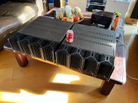
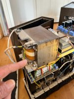
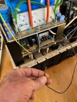
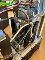
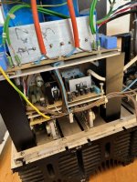
Just collected these 2 this morning.
I’m no weakling but these took all my strength to lift them .
Built by a medical doctor ( now deceased) whose hobby was electronics and his passion was hifi .
These drove 4 speakers, the fronts were about 6” tall and atc’s at the rears .
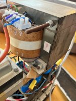
The son said they’re 1000w each and were originally designed to have triple outputs bass/mid/treble but at some point the builder of them decided to change them to a 2 output design ( just as Alzheimer’s kicked in ! ) this might explain the unconnected brown wire .
SO should I power them up ? ( and run ) what would you guys do ?
I’m no electronics person, just into my hifi .
I was thinking of making a 300V DC supply for tube preamp projects using parts I have taking up space.
I wouldn't mind using a couple of 0D3 VR tubes, since I have a couple and they glow a pretty lilac color.
I also have a couple of 6AV5GT tubes I'll never use.
So here is what I've come up with:
In simulation it looks too good to be true. Which means it probably isn't going to work. I have questions...
1. Will the 0D3 tubes strike reliably? If they don't, will that pop the LM317?
2. I figure the output voltage will come up slowly as the 6AV5GT warms up. During that time the pass tube is warming up, will the LM317 get over-voltaged?
3. The value of R4 was chosen to draw 10mA, which I think should be enough to light up the 0D3 VR tubes. Is 10mA too much current for the LM317 reference? I usually see 240 ohms in that position, which means 5mA.
4, I can't visualize what the circuit will do while it's warming up. Do any of you more experienced and knowledgeable folks see something wrong here?
Here's what LTspice thinks the ripple rejection will look like, with the circuit as shown above, with 1V AC ripple riding on the input DC:
HiVi Rt1.3we isodynamic tweeters
Tectonic BMR full range
Dayton RS180p-4
all with just a few hours play time. Tweeters were mounted but never connected.
$120 plus shipping from 30047.
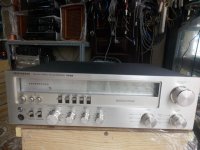
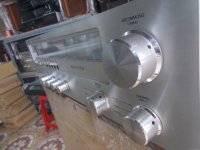
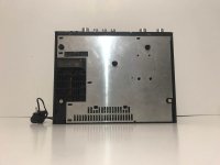
Fault: No input selection then cuts out.
Remedy: Replace 2 x 100mF caps in power supply module and drive belt on rear input selector panel motor drive.
Hallo all,
Can anybody plse help with a relacement for a transistor. E1a4a. I cannot find a datasheet on me life for it. It comes out of a ECU.
Much appreciated
Hi there!
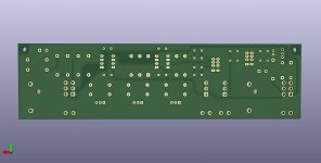
Im trying to build a input buffer for UCD250LP.
This is my first attempt to design a PCB, I need to get feedback.
Its based on the recommendations in the ucd 250lp datasheet.
Anyone care to take a look at it and see if I'm doing some really bad layout/design? Please 🙂
I guess there is a lot that can be done better. I know it looks like s**t compared to other pcbs I have seen.
I can share the KICAD files if anyone is interested.
Schema:
Top layer:
Bottom layer:
Pin assignment
My plan is to do input buffers for the ucd400oem also.
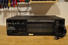
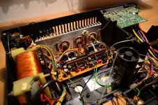
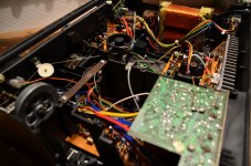
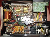
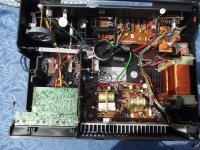
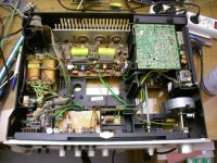
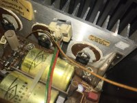
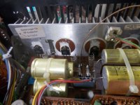
Outside image of this device are here: https://www.audiovintage.fr/leforum/viewtopic.php?t=59293
Replacing of the red AEG rectifier by single diodes is an easy task - most effort is the elimination of all contact resistances on the pots and switches so as the melting of numerous solder joints.
I am surprised by the good sound character and the reliability despite the age (no hot spots on PCB like to observe on various very expensive Mark Levinson amplifier devices) - thus highly recommended for used purchases.
Hi!
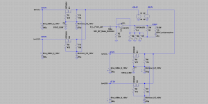
I would like to try connect the amp like at attached picture, I need you advice which chip has the chance to work without oscillation with the gain set 10 times or higher, it should have diff input.
The reason for this is curiosity, compactness, simplicity, efficiency and possibly gorgeous sound (like in other AB class transconductance amps, for example the link:https://www.diyaudio.com/community/threads/lm1875-transconductance-amp.270956/ ).
thank you in advance for any suggestions!
Hello,
Sorry for admins if i put in wrong section, you can move freely to better one (if correct section even exists on diyA). Anyway, i enjoy this forum a lot so i decided to share it here.
Anyway, as you know HD800 has terrible peak at 6kHz. Between HD800 and HD800S sennheiser has added an interesting thingamajig in the center helmholz hole of the driver assembly which has been previously emulated (i wont say copied, because for example the superdupont mod which this follows, differs in all but the principle)
Here is how a bare driver in an earcup looks, we will be retuning this resonator in a high Q manner so as not to negatively impact other frequencies, only to absorb resonance at 6kHz. Login to view embedded media
PROCEDURE
Resonator is basically a similar take on SDR already. I will not BS and say they must be some gold doped magical materials, total cost of materials was probably 2€, just stuff that seemed vaguely appropriate i found in a random hobby store (only one in my city).
We have some felt material, creatology foam like material, and furniture pads (you put underneath to protect floorboards). Ignore the coaster mat, that is for another day.
I wont go into too much detail about construction but outer diameter of all is 14mm, we need hole punch of that size in everything.
Then we do 5mm punch in felt and foam, and 10mm punch of furniture pads.
Then find a random business card and make a 14mm donut with no hole from it as well.
The stack is felt-foam-pad-pad-pad-businesscard (depending on the thickness of your pads it might be one more or less). Total height needs to be 7-8mm.
Just cram this bad boy in there, so that bottom is pressing against bottom, and top is flush with top.
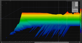
Before we begin,
Do not use my measurements as a metric for what they sound
The rig was a flat plate and does not capture any pinna or ear canal interactions. It does not have headphone compensation curve applied.
The only goal of the measurement rig was to be self consistent and repeatable, to give us a relative change (delta).
To test this, measurements were performed by taking away and putting back on the headphone, this would always capture a slightly different transfer curve
You can see for example that the bass area differs due to a different seal achieved on each run, and the very highs somewhat as well due to the different cup interactions with the mic when it is positioned slightly differently
Yet despite this the whole midrange and the 6kHz peak are in excellent agreement
Then an RMS average of these runs was taken to make it easier to interpret later
BEFORE measurements
AFTER
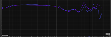
AVERAGES OF BOTH (Before = red, after = green)
Sweeps were performed with identical settings, and trace was not realigned, so seems like overall efficiency is slightly higher as one trace hovers above the other.
Peak seems to have shifted up by about 150Hz. There seems to have been created another peak at 11k. I cannot really hear it because its narrow, or maybe its a measurement thing, but who knows.
Midrange isnt attenuated and if anything got a little boost at 1.1k (1.5dB).
After re-aligning the peak difference (83.31-78.81 = 4.5 dB). This is DEFINITELY noticable, as it also affects things from basically 4 - 10k. Sounds a lot less harsh and agressive, a lot more listenable.
It is overall a positive change, but if i had to say anything, i would have liked the resonator to be just a little more high-Q, because i didnt necessarily want to decrease 7-10k part, but its all good in the hood.
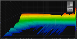
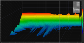
CSD BEFORE
AFTER
All settings identical, nothing changed, zoomed, rescaled, whatever.
Also, ignore below 300Hz and above 10kHz because as we noted above, these were variable between individual measurements, and everything in between had excellent agreement.
The image is the same between all individual measurements, even if i wanted to i could not make the bottom look anything like the top.
A very significant reduction in stored energy and ringing. Note that this was already at a quite low level and wasn' t that obvious to begin with. Perhaps this is also a part of why i noted it to be less "harsh"?
Interestingly, it seems to work all the way down to 1khz, cleaning up it up quite a bit.
Hi Guys
Going to experiment with XKR very nice XSD speakers. No wanting to confuse the thread there, thought it's better that I start anew.
Question pls : Have gotten 20pcs 8 inch woofer with Qts of O.99 with sensitivity of 87 db at 8 ohms each, will use 10 woofers per speaker. Full range is a Coral Flat 8 with sensitivity of 94/95 db 8 ohms.
How do I wire them up together to get 8 ohms if possible ? Will test out with single speaker connection first no bi amping
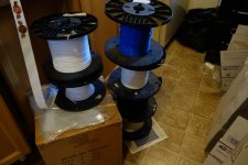
I have 5pcbs for sale; ordered 10 from JLCPCB and 4(+1 as backup) will be used for my mic preamp
price - 2EUR per board + shipping cost
(my total price was ~20EUR with VAT tax and shipping to Poland for 10bards, so asking only for manufacture cost).
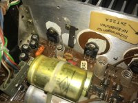
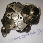
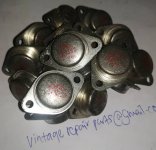
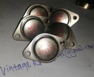
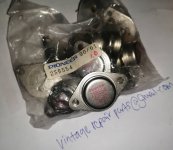
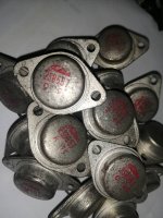
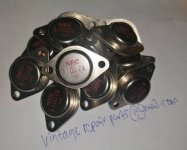
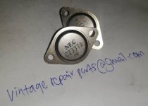
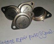
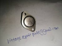
I am repairing the power supply of this soundstream amplifier. original mosfet transistors are 80nf70 47ohm gate. I want to substitute 3205 and 47ohm gate. I have the biggest problem with gate bipolar transistors. the original reference is D882M and B772M, of which I cannot locate nor a good direct replacement in the same packaging dpak - to252.
Had some questions about planning the interior design PCB, power supply etc. It would be cool if I could talk to someone here in detail about everything
So,
It just happens that I do not have an amp (don't ask how I lost it) anymore and I really need one bad. As the next project in line is ~86dB sensitivity scanspeak 2way, I am looking for 50+ wpc design. The listening room is rather small ~20 sq meters(well furnished) and there's not enough room to fit more sensitive speakers - I obey the Hofmann's Iron Law... And it just happens that I have 18w/8545 pair, 15w/8531 quad seamlessly lying around and there a couple Troels designs that I am considering building.
The main constraint is the build complexity. I am not really an experienced diy guy, but I can construct things, solder, read circuits, measure, source parts.
I need a PCB. And I am looking for a well proven design that does not require much experimentation to make it run stable. Successfully built the dcb1.
What are my choices?
Second hand market is pretty much dead in my country. Also I consider the commercial audio devices to be insanely overpriced.
Mr Pass's designs need efficient speakers - 25watts ain't gonna work with ~86 db sensitivity speakers well or leave no headroom at all. The 50 watt F5V2 needs hard to come by jfets, and for the AB100 the world has run out of the output transistors.
Tubes?? Maybe some KT88 push pull could work... Point to point construction, designs are old, well tested and polished...?
Chip amps? Lm3886 Done Right might be tempting. Easy and cheap design, proabably not that good in reproduction satisfaction though as compared to class a constructions.
Any other class AB solid state amp that I might be not aware of? Going through all the solid state forums threads I've noticed that it is really hard to come by with PCBs for sale anywhere...
I am just looking for a relatively easy build with parts that can be sourced at the moment..
Or should I just sell those scan speaks, build myself some other small speaker pair that is more efficient (~91 db if that is even remotely possible) and build myself first watt m2x?
And of course, apologies if this is not the right forum...
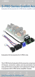
Hi everyone, I just joined though I've been reading this very enlightening forum for years. I'm a total newbie with this stuff, so I have some questions about setting up a Pascal S Pro 2 module.
I'm wondering if anyone knows where I can get the wiring harnesses for a Pascal SPro 2.
A local store has a new old stock module , but no harnesses, and Pascal won't sell them one.
In this photo of the Pascal evaluation kit, I can see the different i/o harnesses.
I assume getting the stereo i/o module is probably a tall order as much as I'd like one. But I'm hoping the other harnesses can be acquired somewhere.
I don't see the IEC power harness in that photo. Is that a generic connector and if so, where could I get one? If not I would need to find one of those as well.
Hi All,
any users of Sprint layout able to answer the following:
I've created a pcb outline from a scanned image - but when I run DRC it picks all the drill holes showing them with a green square and saying they're too close? That would seem odd as the original circuit is from the 1980's and is quite basic, just single sided. This is my first time using it so I may be missing something simple in how I traced the original.
Any assistance is gratefully received.
Thanks
Joe
Some time ago, I built a pair of Fostex Speakers (picture below). The drivers are FF165WK and FT17H super horn tweeter and the design is bass reflex following the FF165WK bass reflex enclosure recommendations.
I have next project todo for my turntable. Currently based on vintage regular speed controller, I have using correction with stroboscope based solution as it was defined by vintage TT.
In my point I could use some Arduino (as example Nano) to correct speed of TT automatically based on sensor to calculate number of silver (white) and black dots of strobe.
I have found ky-033 model that could be used to detect white/black lines and working with multiple Arduino boards.
As all could see on picture - the size of sensors is not so small, but dot's on my TT is about 2-3 mm each other.
So my question is:
do someone knows limit about detected black/white lines by this module (it has minimum distance about 1sm from the line) but I never seen limitation of line size.
need to understand the speed limit of detection (as I see this is about 100 white and 100 black dots on the 1 loop). So with 33.3 / 45 of TT speed we will have 3300 * 2 minimum detection in 60 seconds. Does this module could support this speed of detection.
In case this module is simple and not enough, may someone knows some other module with required spec's as detection of 2-3mm lines (dots) and with possibility to detect up to 4-5 thousand dot's per minute.
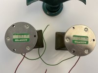
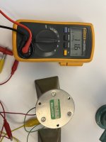
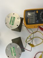
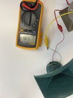
For sale have a pair of Altec 3000 tweeters and a third one that I purchased to have a spare diaphragm. In very good shape and perfect operating condition. US shipping only and paypal only. Shipping included at my asking price.
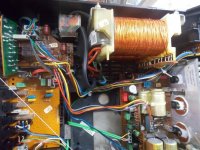
Finally got my hands on a broken RD1000/1, and it’s a pretty cool amp. Much more basic than the older slash series stuff, and makes use of more modern higher power chips and FETs. Love the die cast case too.
The power supply FETs, gate resistors and BJT drivers were smoked but the 494 still makes gate pulses, so I ordered that stuff and it’ll be here next week. What I’m having trouble understanding is the output stage.
Looks like IRFB4410Z FET pairs being driven by IR2101 drivers, but it doesn’t appear to be wired like I’d expected. Can anyone confirm that’s what the drivers really are, so I know I’ve pulled the correct data sheet? It’s U12 in the picture.
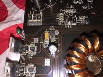
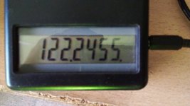
I restarted my old project of a FM tuner using tubes and permeabilty tuner, I already talk about it some years ago here. Here is the first step, the local oscillator running 12MHz above the incoming signal, such is the FI value choosen because of better image rejection. Also the frequency meter is displayed.
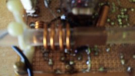
The tunning device is very crude still, but I am satisfied. A rod of acrylic material of about 9mm external diameter over which a short piece of copper tubing is provided. Over the copper tubing, a thin layer of electroltic copper was deposited using copper sulphate and an electrolytic solution, for reduce the superficial resistance and increase the Q of the tunning device, in fact oscillator's grid bias decrease less than a volt from one end to other of the oscillating range.
The tube shown is a ECF801.
Next steep is more difficult, the ECC88 cascode RF amplifier.
The vacuum feature never really worked, but while it gets the job done, I'm wondering what else is out there?
Looked at Panavise options. They look nice, but get a little pricey.
Then there are the helping hands things with alligator clips on flexible arms.
And these little clamp things
I need some help and your advice will be very appreciated.
At the moment, I am using the RPI 4 as end point. The Khadas tone board is connect with the RPI 4 by USB Khadas cable found in the box. In order to improve the sound (actually I am happy with the RPI + DAC but I would like to make some experiment), I want to power the KTB using the GPIO connection. My question are:
1) If I use the GPIO to power the KTB, can I sill use the USB-C just (link to RPI) to input the signal?
2) If I use the GPIO to power the KTB and the USB-C (link to RPI) just to input the signal, should the USB cable be without +5V connection (red wire cut) in order to avoid a double power supply or useless connection (which can introduce noise)?
3) Could you suggest a power supply you know is good in your experience, without sell the house? Is the IFI Ipower 5V a good solution? Do you have a better one?
4) Please could you suggest a good USB cable in your experience? without sell the car..
5) Do you know if USB cable has to have demanding 90ohm +-15%? Or less is better?
Thank you so much in advance. Thank you for the attention.
I m making a 2 channel amplifier that has 2 wires for each channel for the input that is used for RCA. Now I also want to use XLR along with RCA inputs but I’m not sure on the XLR as it has 3 wires Hot, Cold and Ground, how would the wire to a amplifiers board that has only 2 inputs for 2 wires not 3?
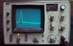
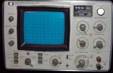
Good condition, no broken knobs, all functions work fine. Chip in upper left corner of reticule glass, but not in usable area and doesn't effect functionality. User manual on CD if you would like, but its available on the web for free.
I've been using it regularly for about five years with no complaints, but I got a good deal on an HP3589A.
$300 USD + shipping (UPS, ~35 lbs). Paypal or cashiers check only. PM if interested.
Bill
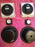
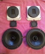
I have a pair of Bextrene cone laminated 8 inch bass driver taken from a pair of B&W DM2.
This is a replacement driver stamped May 1993 and not the original DW200/2 bass driver designed by B&W the 70's. Limited play in the cone can be observed as the coil tube hits the back plate. On my Sansui 881 it hits the back magnet at around half the volume making horrible noises.
I would be interested if it would be worth the effort to refurbish these by doing the following upgrades:
1. Replace the rubber surround with a rubber surround that has a wider bubble / bulge so that it allows for more flexibility and potentially bass. Original driver DW200/4 has wider bubble / bulge by 5mm as a consequence it does deliver more bass than this one.
2. Remove the back plate and add a metal ring between the magnet and the back plate that would leave more space for the core tube to move at the back. I'm only thinking of refurbishing these as I want to get more power out of the DM2's and these have a 700g heavier magnet than the DW200/2 original driver made by B&W in the 70's.
Has anyone attempted to do such extensive refurb. Would I risk damaging the magnet by trying to remove the back plate?
Hi everyone!
I'm using Li-Ion battery supply for a headphone amplifier. I would like to replace the batteries with a very good linear regulator with minimal noise. I need max. 0.7A output. I have a 10VA toroidal transformer with a 9VAC output and was planning to use that if possible. But I have no clue as how to find a very good regulator suitable for this. Ideally something I could buy already assembled or just a circuit diagram so I can assemble one (I'm not an electronics designer but I can handle a solder iron) 🙂
Hi All,
I need a fast & big (15-18" driver) sub for my home theater setup only for LFE use with movies to match my Pi Theater 4 LRs. And, yes, as cheap as possible since i will not use it for music bit just for cine-fun 😀
Suggestions?
Thanks
I have an older Infinity Kappa setup in my car, the front has 60.11CS 2way component set
I ordered a set of 20mx with their included bandpass crossovers thinking I could add them on, but upon further research, it turns out they are designed to plug into the newer 60csx crossovers which have some kind of switch to tell them the mid system is attached, but I can't find any technical info on it.
Should I just run the mids on their own channel off the head unit? If I were to run them on the same amplified channel as the components, could I parallel it to the woofers leads (which already passed through their crossovers) or I have to parallel them before their crossovers?
I'll post some pics so others can see this 20mx crossover
Hello all, I’m really needing assistance in finding replacements (equal to or superior) for MTP8N10 and MTP8P10 n and p channel mosfets.
I picked up a fairly rare amplifier, a Superphon Maxx 806 which was designed by Stan Warren of PS audio. Unfortunately it’s so rare that I can’t find any service or schematic info on it anywhere. It uses two of each in the output of each channel, so the amp has four of the N channel and four of the P. One channel has had the outputs destroyed.
Before I opened the amp I saw that they were TO-220 device and was praying for BJTs, but no luck. I know that matching for fets can be trickier and I’m having no luck finding cross reference online. I was hoping for maybe RFP8N10, but no.
Can anyone point out available devices that should work as drop in replacements for these two devices? Hopefully someone is familiar with them as I can’t find much info on them at all.
After unintentionally hijacking the Sony VFET Part 2 thread asking for opinions
on speakers that excel with Papa's amps, I've decided to ask my questions in a new thread.
What speaker design do you find most satisfying and/or revealing for our beloved 25 watt Pass amps?
Is your amp SE or PP or do you have both?
Do you prefer a 3 way, 2 way, passive, biamped, or full range?
OB or box?
Ancient technology or new high tech drivers?
I'm especially interested in hearing impressions from those who have experienced
different combinations of the above to see if there are common threads that arise.
The following and posts 2-18 were kindly moved by the moderator from the VFET thread to this new thread: