Yamaha A-S501 vs Marantz PM6007 vs ...

Hy,
I'm looking to buy new amplifier for living room (around 20m2).
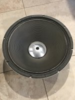
Currently I have a pair of old Pioneer CS-770 speakers, those will also be replaced a bit later, so they dont play a big role. But I will likely get something in similar size and power rating.
I listen mostly 80s & 90s rock, hard rock, pop. I used to listen to alot of electronic music, but as I'm getting older I'm moving away from it. But I still do like to shake the house from time to time.
This will be my first newer quality amplifier and I'm not sure what to expect. I want rich sound and bass cannot be sacrificed.

I'm looking at Yamaha A-S501 and Marantz PM6007. I'm also open to any other suggestions in this price range, but I must see if I can get it localy.

I like the looks of Yamaha better, but that is it for now...
I know nothing will be "the best of the best" in this price range, but I would like to hear opinions.

Thank you

Modding the SMSL SA-36A Pro

So I just got my SA-36 but it's the TDA7492PE version.
I opened it and it has 2 4400uf 16v capacitors. Would there be any benefit in swapping them for 2 4400uf 25v ones? And can I have those 2 and add a 2200uf 25v extra?
I'm currently using a laptop power brick 19v 3.41A but I'm guessing it's not delivering all of the power. The chip is supposed to handle up to 26v.

Will post pictures of the replacements I bought.

THAM 21, stupid idea?

Hi all,

I'm busy designing a subwoofer to be used at the scuba diving team "watering hole" clubhouse. It's a fixed installation with 4x JBL EON712's used as tops. I have space to fit 1 sub of about 1x1x0,7m. Normally this is used for background music, but we also have parties about 5-6 / year. Total floor area is about 80m2, total volume is about 240m3.

For now I have a 500W amp and plenty of DSP (DEQ2496) available to drive this.

I was looking at the THAM 18 and just for fun I decided to scale it up by 1.167X and sim it with the Beyma 21QLEX1600fe. Sims look really good to me.
Is this a totally stupid idea / am I missing something. Or could this be the sub to really pressurise the room if we want to?

Any toughts appriciated!

Attachments

  • Acoustical power.jpg
    Acoustical power.jpg
    47.7 KB · Views: 283
  • Input parameters.jpg
    Input parameters.jpg
    63.9 KB · Views: 236
  • Schematic diagram.jpg
    Schematic diagram.jpg
    32.6 KB · Views: 257

Welborne Squeezebox Power Supply Schematic Or PCB Needed

Greetings all. A good friend had this Welborne Labs 5v Squeezebox PS kit laying around and asked me to assemble it. The kit appears to have all the correct parts, including transformer, for the Squeezebox 5v power supply but the board supplied is incorrect. The supplied PCB is too small for the supplied components and the enclosure. I searched for Welborne labs squeezebox schematic but nothing popped. I was thinking of getting a board made or doing point to point. There is not much room under the board so a PCB would be the best solution with supplied enclosure. Any suggestions?

I attached pics of the kit with incorrect board and an assembled squeezebox PS pic snagged from the internet. Welborne labs is long gone so no help from them.

Thx.

Attachments

  • 20221108_104736.jpg
    20221108_104736.jpg
    301.1 KB · Views: 158
  • wb3.jpg
    wb3.jpg
    81.5 KB · Views: 155

Pictures of rebuild, recapped and refurbished Onkyo M-508 power amplifier.

I am uploading pictures of my rebuild, recapped and refurbished Onkyo M-508 power amplifier.

Attachments

  • 20190907_194821.jpg
    20190907_194821.jpg
    473.7 KB · Views: 242
  • 20190907_214649.jpg
    20190907_214649.jpg
    504.6 KB · Views: 226
  • 20190907_214652.jpg
    20190907_214652.jpg
    459.1 KB · Views: 215
  • 20190907_224735.jpg
    20190907_224735.jpg
    467.7 KB · Views: 226
  • 20190907_125423.jpg
    20190907_125423.jpg
    291.2 KB · Views: 214
  • 20190907_130057.jpg
    20190907_130057.jpg
    334.4 KB · Views: 208
  • 20190907_130101.jpg
    20190907_130101.jpg
    288.2 KB · Views: 211
  • 20190907_130417.jpg
    20190907_130417.jpg
    370.1 KB · Views: 214
  • 20190907_133051.jpg
    20190907_133051.jpg
    371.3 KB · Views: 214
  • 20190908_005803.jpg
    20190908_005803.jpg
    378.5 KB · Views: 217
  • 20190918_135616.jpg
    20190918_135616.jpg
    658.6 KB · Views: 239
  • 20190918_141145.jpg
    20190918_141145.jpg
    522 KB · Views: 218
  • 20190918_173657.jpg
    20190918_173657.jpg
    661.3 KB · Views: 225
  • 20190918_175904.jpg
    20190918_175904.jpg
    465.1 KB · Views: 225
  • 20191018_211107.jpg
    20191018_211107.jpg
    452 KB · Views: 225
  • 20191018_211113.jpg
    20191018_211113.jpg
    550.1 KB · Views: 205

Onkyo Grand Integra M-508 power amplifier rebuilding

Hello guys,

I am new to this forum and i personally found this forum very helpful and helpful people.

I am rebuilding recaping my onkyo grand integra m-508 power amplifier. I have already replaced main 8 filter power capacitors with 100 volts 10000uf cornell dublier capacitors. All other capacitors i bought are elna silmic ii nichicon fine gold nichicon muse and Panasonic fm.
I want to know that originally at c413-c416 there is nichicon muse 16v/10uf polarized caps and these muse caps are not available anymore only nichicon muse es bipolar are available in that value so i bought nichicon muse es bipolar caps instead of polarized capacitors. Can you people help me telling can i use bipolar nichicon muse es caps in that place instead of polarised?

My other question is can i replace c463-c466 polarized 3.3uf 50volts electrolytic caps with wima film caps?

Picture added of factory fitted nichicon muse polarized capacitor (green ones)

Help will be highly appreciated.
Thanks

Attachments

  • 20200412_035122.jpg
    20200412_035122.jpg
    999.9 KB · Views: 663

Guidance for adding tweeter to MJK open baffle speaker original version

I recently built MJK's OB speaker and am interested in adding a tweeter. I used the Eminence Alpha 15 A and the Fostex FE108EZ. I have a set of Tymphany BC25SC55-03 1" square frame tweeter from another project that I temporarily hooked in series to the full range driver just to see how this would impact the sound. There is no question that having this pointed to the ceiling added to the top end. That was a quick test and I removed the tweeter. I am hoping others have done something similar and can share with me the tweeter and crossover they used.

For Sale Little Bear T7 Tube buffer/RIAA preamp NIB

New in the box Little Bear T7 Tube buffer/RIAA preamp. My brother purchased this, but then traded it to me for a modified NAD integrated amp. I was going to mod it, but never got around to doing it, Totally new, stock, never even listened to. Some time along the way I lost the owners manual.

Prefer CONUS sale.

Asking $39.00 plus shipping.

LittleBearinside1.jpgLittleBearinside.jpgLittleBearSide.jpg

Icepower 50asx2 no sound

Firts of all i just wanna say hello everyone.


Im confused this class d amp icepower 50asx2 no signal/no output. When i use multitester on speaker out then tap input pin there is signal. But when speaker connected no response. I try to bypass L100 inductor no luck same issue. Is there someone experience this issue.

Thanks and advance.

Attachments

  • 20221024_195201.jpg
    20221024_195201.jpg
    437.4 KB · Views: 214

AKAI GX77 slow wind problem

There is a "big issue " about this reel many complain about the same problem which is slow RW and FFW when you wind the tape on any side the "engine" runs out of steam and often stops completely Obviously at this condition or even with less tape loaded between the reels starting RW or FFW respectively has also no effect Engine dont have the power to start.

Many post questions about it, and looks like a design flaw rather than a damage Still there is an other internet urban legend regarding a couple of resistors that fail (never found one failed though ) but of course winding problem has absolutely nothing to do with it .Yet again no matter the plenty questions or the urban legend nobody seems to come up with a solution .

I dont understand why this is happening on the internet . People that have no idea about electronics post solutions related to the blue resistors that obviously have no effect one the specific problem .

Anyone with ABC knowledge of electronics will see in the first minute that the blue resistor with one 1N 400X diode is there to consume the reverse voltage produced by the motor when spins free on the opposite direction . you don't want this reverse voltage against your drive transistors ...Alike protection diodes for reverse current to any transistor operated relay drive circuit .
You might have issues there but none of them is related to the slow REW or FFW problem . period !!!


Face it !!! the design has a flaw ...

Real reasons that might cause the problem
---Dirt and tape left overs all over
---Age problems regarding capacitors/resistors/contacts on the psu of 18.7 volts
---Aging of the motors
---Fatigue on the plastic gear ( created by spinning belts)
---Problems on the belts
---Tape/reel itself related issues
---Remote but possible: alignment issues
---In general and even though the design looks pretty cool problem remains that tape travels through a lot of barriers to end up in the other reel and that on its own is an issue .

Now you may choose any of the problems and any possible combination between them and you will end up with a slow wind speed ...Often its so slow that either the tape will stop completely winding at some point at the end, or if needed to start winding while some amount of tape is winded in the other reel then start is impossible .

There is a vanished guy that offers a fix but as far as i know this guy doesn't answer email or takes too long to ship parts or what he calls kit ....

Got it fixed permanently !!!
The way i did it offers

---No more than 5 euro of parts and one hour of work
---Increases wind speed side to side by far
---Reduces stress on belts and plastic gear
---Will work the same well even if belts inside are very loose/old
--- will be able to start in very high speed at any position of tape or type of load
---It will work extremely very well even if tape drive is dirty or belts are old or power supply has age issues or motors have age issues

Most of all has absolutely no side effects either in electromechanical points or from any sound or any other aspect ...

Kind regards
Sakis

Cambridge Audio Azur 840A V1 shut off.

Hello.
I bought a cheap Cambridge Audio Azur 840A amplifier. It goes off by itself between 2 and 15 minutes. CAP5 system says nothing.
In factory service menu all counters is OK.
I opened the amp and there are two capacitors C25 and C26 inflated a little.
Can it come from that?

Service manual

https://mega.nz/file/AThnRLIC#pw_XPcdZj1O5gSE7jPfl8sCsuQDRpYkN3DNUdBRpF3E

WTB (or trade): 1 x 2SD188 and/or 2SA627 BJTs

I'm repairing a Marantz 2220B for a friend with dead output transistors on one channel, which needs to be replaced.
Anyone willing to part with one of each for a good cause?

Again:
1x 2SD188
1x 2SA627

I'm buying or we can trade.

Trading.
I have tons and tons of new never used (stock) high end op amps + some discrete Melcor 1731 op amps, potted by yours truly. (photo attached)

Discrete Melcor 1731 op amp, with Mill-Max gold-plated pins. Potted.
AD797 - Ultralow distortion, ultralow noise single op amp. DIP-8.
AD8620 - Wide bandwidth dual precision JFET op amp. SOIC-8 or mounted on a DIP-8 adapter with gold-plated Mill-Max pins.
AD8610 - Wide bandwidth single precision JFET op amp. SOIC-8 or mounted on a DIP-8 adapter with gold-plated Mill-Max pins.
AD712 - High speed, precision dual Bi-FET op amp on DIP-8 adapter with gold-plated Mill-Max pins.
AD827 - High speed dual op amp. DIP-8.
AD845 - Fast precision CB-FET op amp. DIP-8
OP27 - Low noise precision op amp. DIP-8
+ Many many more. Write here or send PM if you got what I'm looking for!
  • Like
Reactions: wputera

TQWT design and Hornresp

I was looking at this box since I have a few CHR-70v3s in addition to attempting to designing my first TQWT for another driver. I wanted to see how Hornresp would model the results of the DDVP-10-ML. I wanted a proven design to give me a baseline to better understand Hornresp so I can model my own ideas. Perhaps my numbers are off but the graphs do not show this box/driver combination to be a good match. Would anyone else be willing to take a stab at it and see how your results compare or offer a "sample" of a well-designed TQWT in Hornresp for the CHR-70v3 that I can use as a template? I listened to several "air recordings" available on Youtube like this and this and it sounded pretty good assuming it was well recorded and my B&W headphones were not failing me which was confusing compared to my modeled response. I don't have endless time and money to indefinitely try things so I am leaning on the modeling software to help- like everyone else! QW designs, Full Range systems, and Hornresp are all new to me, so thanks!

Woofer troubleshooting "ringing" fixed by depressing rubber surround?

Hi All,

I have a very odd issue and I know this is the best place to ask, hopefully I'm not alone!

3-4 times a year I start getting woofer "ringing" on one of my woofers, a "warbling" distortion in male vocals, it's been happening for years on (I think) all four Seas 5" woofers, gently pressing all of the way around the woofers rubber surround (with white gloves on) fixes it till next time.

Anyone seen this, could it be aging rubber, a stiffness, maybe its drying out (the speakers are 13 years old), any thoughts on "lubing" the rubber, I'm in Sydney and the room can get very hot in the height of summer, like around 35°C (if we are out)?

Thanks for looking.

Cheers
Richard

Daniel Hertz Levinson M1 wow

hi all
i just found some pics of this amazing speaker on the net M1
first impression is WOW its big
i wonder how it sounds

i,ve been looking for ages for a design like this to use as a base for my next diy speakers but how would a 12" driver go producing midrange ?

and what about a compression driver for highs ,i know they use them alot in the pro industry but are they good enough for home audiophiles

any way i reckon they look grouse and would proberbly blow your socks off

any oppinions ?

regards sheafer

Critique my rough design plan please?

So I’ve decided to go the OB/Fullrange DIY option over the Maggies with OB subs….I guess I just appreciate a challenge!

My initial thoughts are two 15” SBAudience OB woofers for each channel…..one downfiring into SLOB type slot and the other forward facing on a 20” wide U baffle. Above would be a fullrange driver within the 6-8” class.….something that will handoff nicely to a 15” woofer in the 250-300hz range and extend to 10k…….i‘m 55 and there’s not much I can hear above 10 anyways.

My thinking here is the slot loaded woofer will extend the bottom end a little deeper. Was also considering using it in a .5 configuration and a low pass around 100hz but not sure the extra component or effort is needed since it’s going to be mechanically HF attenuated firing downward and into a slot. Thoughts?

For Sale 9pcs of high end AC US Plugs - wattgate iego furutech , new

I have for sale the following AC plugs, all are new, unused, without box.
I had a plan to use them year ago when I had US power conditioner, but eventually never used them.

szt = pcs

4 szt Wattgate 330i Audio Grade Gold
2 szt IEGO TI2020 GOLD
2 szt Wattgate 5266i
1 szt FURUTECH FI-11M

350usd shipped worldwide and paypal fee included,

Attachments

  • IMG_6016.JPG
    IMG_6016.JPG
    828.9 KB · Views: 130

Can you identify this old tube amp?

I picked up three consoles on the weekend because the person wanted them out of the house to get ready to sell.
A westinghouse ra-509 "belvedere" and a westinghouse 823 and the last console had no name, It was quite old.
So in the Belvedere cabinet were the two pieces pictured below, along with the ra-509 tuner. It appears these were added to this unit.
The amp has no name but has some Canadian Hammond iron. The power tubes in push pull are 6a5g's and there is a 6sn7 and a few other tubes as you can see. The power transformer made by merit and is 800vct 200ma. The output is a Hammond 1715 PP 5k Can anyone ID this amp?

Attachments

  • PXL_20221104_034844887.jpg
    PXL_20221104_034844887.jpg
    361.1 KB · Views: 246
  • PXL_20221104_034901544.jpg
    PXL_20221104_034901544.jpg
    601.1 KB · Views: 249
  • PXL_20221104_035019638.jpg
    PXL_20221104_035019638.jpg
    535.3 KB · Views: 245
  • PXL_20221104_035037230.jpg
    PXL_20221104_035037230.jpg
    527.3 KB · Views: 245
  • PXL_20221104_035134102.jpg
    PXL_20221104_035134102.jpg
    488.9 KB · Views: 243
  • PXL_20221104_035140947.jpg
    PXL_20221104_035140947.jpg
    601.7 KB · Views: 247

Capacitor Replacement options

I’m having an issue with getting specific rating for capacitor replacement on an amp power board, it’s an 120vac amplifier (none car) but it’s a general question that could use the same logic I believe.
the originals are 6800uf 80v and they are 8units in the power circuit, they are arranged series parallel where both amp module is tapped on a shared power delivery (not independent arranged banks like dual power supply) just one big bank serving both audio modules.
my question is can 10000uf 80v caps be used to replaced them? Will it have too much capacitance or will it affects ESR?
Let me know if the higher values have any negative adverse issues if I used them.

Attachments

  • image.jpg
    image.jpg
    719.1 KB · Views: 168
  • image.jpg
    image.jpg
    595 KB · Views: 168

Trouble finding a preamp board with high quality Bluetooth and classy display.

Hello forum members, I took the time to write an introduction but it disappeared when I went to a different window on my phone. Briefly, I’ve been a member on diyma for around a decade and have pretty much come to endgame with my car stereo. It’s all raw drivers except the Audiofrog GS25’s as midrange. Lpg26na tweeters, Epique 7” as midbass and two ultimax IB through the cargo area floor, Minidsp 8x12.

To the point, I’ve turned my attention to building a mini receiver and bookshelves. The bookshelves are pre made .52cf enclosures with the tectonic bmr 2”, Anarchy 704’s and 8” Dayton Reference passive radiators. The receiver is a 3x7x8 electronics enclosure. The guts are a 24v 9a power supply board, Dayton kabd 2x50 and 4x30, Parts Express preamplifier board and little odds and ends.

I don’t need a preamp as the kabd boards are basically turn key solutions but it’s for the sake of art that I want a classy looking display. The preamp I’m about to use has a lesser Bluetooth, won’t control power to the amplifier boards and just looks cheesy to me. The problem is, I’m becoming more and more convinced that most diy preamp displays look cheesy and or have silly writing on them. The other one I would consider on PE has “music world” on the display most or all the time I think. I looked on the Google and eBay but not much seemed worthwhile. eBay has some interesting looking stuff but a in depth description is nearly nonexistent.

What I’m hoping to find is something that has a relay to control power to the amplifier boards, FM radio and something comparable to the aptx Bluetooth that the amps have, remote would be cool if possible. If I’m not already asking too much, none of those features matter unless the display looks high end-ish. I’m planning on fitting a nice finished 1/4” oak board as the face, possibly stained with something complementary.

I did a search before posting this but I didn’t pull up much unless I wasn’t looking in the right sub forum. I’ve been able to find everything else on my own but I’m stumped on this. I don’t have the skillset to diy a board from scratch. If an established member builds something like I’m talking about I’d consider going that route. Thanks for reading 🍻

Want to buy Whammy and/ or Amb M^3 headphone amp

AMP PURCHASED!

Just Like the title says I would like to buy a Whammy and/ or M^3 headphone amplifier.

Build quality is most important. For the M^3, I am fine with additions like a pot gain control, bass boost, fancy chassis etc....

The Whammy builds I have seen are mostly stock which is fine too.

I prefer the OP 627 or 4627-1 op amps and will pay extra to have them installed.

You can contact me here by private message .... or at Head-fi / sacd lover by private message.

I have posted a WTB ad on Head-fi as well.

Musical Fidelity A1 recap components list

Hi,

I just did a recap of Musical fidelity A1, my one is the very early version of A1 I think.
Here is a list of components changed in the pdf attached below. Hope it helps anyone want to do something similar.

Attachments

Othorn for sale

Anyone interested in an Othorn tapped horn subwoofer? It was cut on a CNC and glued together with PL premium. It's a beast and I am sad to let it go but I just don't have room for it anymore. I'm in Los Angeles and it's a direct pickup only. $1200 for cabinet and B&C 21SW152-4 woofer. That pretty much covers cost of materials. It is made out of BB ply and has not been painted or finished in any way. It was used sparingly in my own house.

Car AB amplifier power upgrade

Hello everybody,

I have an older 4 channel car amp, 60w rms per channel @4ohms, 100w @2ohms, 2x200w @4ohm bridged.
Every channel is powered with Sanken 8A 2sa1694 and 2sc4467 transitor pair, rail voltage is 24v @ 12v input.

I would like to upgrade output transistors to a 15A 2sa1294 and 2sc3263 pair to achieve 80-90w rms per channel.
I have 4ohm 125w rms speakers so I would not connect any 2ohm speakers nor use channel bridging as that would most likely kill power mosfets (4x DFP50N06) or rectifiers.

Is this doable, should I choose other transistor pair, what else should I consider replacing, drivers, base resistors?

Full Range Build... Where to Start???

I am looking to build up some Full Range, Single Driver, Speakers. I have been wanting to get a second pair of speakers to offer something different from my '77 La Scala's. I have made some changes to the La Scala's that have resulted in excellent sound... Upgraded Tweeters, ALK crossovers, etc. Very happy with them but have longed for a more relaxed set of speakers that offer beautiful midrange detail, softer highs for mainly classical and acoustic recordings. Would like a natural and musical bass section, doesn't have to dig too deep. Single speakers set ups just seems to fit the bill... if done right.

After looking at many discussions on DIYA and others, I am very unsure of where to start... with the driver, or with the enclosure? I have looked at drivers and I've looked at enclosures... but I haven't seen exactly what I would like to do. I was hoping to get some plans for a larger driver, like 10" or 12". But I am not finding much in the way of plans for these sized drivers. So maybe that is because anything larger than 8" perhaps isn't well suited for this type of speaker design? I have a pair of Altec 417H drivers that are sitting around doing nothing... They are an instrument driver, not hifi, but they sound excellent in a Fender Twin!

I have done some basic calculations with some online calculators for a Bass Reflex enclosure. but I would like to hear from you all if I am starting out all wrong with the wrong driver. I have looked into some 8" drivers from Fostex, Seas and Mark Audio, but zero experience with these brands to even know what the house sound might offer. Also, all the plans available seem to be small bookshelf boxes. Is there a plan for a larger box and wider baffle for an 8" driver? I have the room, but would like to keep the footprint equal to or less than my La Scala's.

Totally fresh to this topic so all information is welcome.

looking for service info on Audiosource AMP TWO

I would like to do some work on my Audiosource AMP TWO (or the ONE, kind of the same amp)
however it looks like Audiosource is one of the hardest companies to get a service manual from
I googled and found a schematic for another one of their amps which is of absolutely no use to me, totally different amp type
I have emailed them but still have gotten no reply

has anyone here had success getting service info on Audiosource products ? what is the secret?

I will try calling soon but want to hear from others before going that route as there might be a particular person I should contact for best results.


I am aware of an extensive thread for the amp 100 but they are not similar products

NEC 2SC3840/2SA1486 Possible fakes ?

Hi guys.

I know, the rule of thumb is to avoid Alitard when it comes to obsolete transistors ! But ! The picture on sellers site is showing NOS NEC 2SC3840/2SA1486. Well, you know the typical transistors from that period, plastic black/green TO-126 case with silverish painted markings on a
rough/mat surface. Something like this -->

v705439726.1.jpg


But what I received is this -->
Probably_fake_2SA1486.jpg
2SC3840.jpg


As you can see. Markings are made with a laser on a shiny surface. The NEC logo on 2SA1486 is missing ! Mind boggling situation. The back plate is a typical NEC transistor shape. You probably already know that Renesas took over NEC business back in 2010 and they continued to manufacture 2SC3840/2SA1486 for some time. You can even still buy them at Digikey but the minimum order is 345 pieces. Does anyone have a picture of these transistors made by Renesas btw ? I also did some hfe and Vceo (breakdown voltage) tests -->

2SA1486
Vceo - 730VDC
hfe - 60
hfe category - L

2SC3840
Vceo - 720VDC
hfe - 90
hfe category - K

So, according to NEC datasheets, these values are in the specified range. So guys, would you be so kind and share with me you opinions. Cheers.

Monoblock based on Hammond AO-39

Been through a number of iterations on developing a power amp for my stereo rig - most recently, a few months back I had a thread for a stereo SE amp built around the 807. I got as far as a crude prototype, but life intervened again. In the meantime, I found an eBay auction for an inexpensive pair of Hammond AO-39 chasses. These were reverb amps for the A100 organ, and have a 5U4-based power supply, two 6BQ5s in cathode-biased AB1, and a 12AX7. Hmmmmmm ... a pair of PP monoblocks with a little more power ... Hell yeah, I'm in!

The original circuit is built around a differential input, and is not really appropriate for a guitar power amp in a number of ways, so I designed a circuit with a Fender-esque LTP on the input and adjustable cathode bias for the power tubes. I chose to use the 6P14P-EV in order to run higher voltages (and dissipation, but as we'll see that wasn't an issue), and the 6N2P on the front end because I have a pile of them and I'd rather use my vintage ones in something where they'll make a difference.

I've successfully built the prototype, and am now stripping the chasses to prep for cleaning and painting. I may or may not reuse the noval sockets, depending on how easily they clean up (and whether I break them in the process).

Power Supply

The original power supply ran the rectifier into a dropping resistor and then to a CRC pi filter, taking the B+ from the second filter cap. This is overly complicated for my use case, so I simplified it to taking the B+ from the first filter cap. Removing 250R and using modern wall voltage raised B+ by 55V, to 370V, well within spec for these tubes. I chose 335V for the screen supply based on simulation results, and the the PI is fed a solid 300V. The 6.3V heaters will be elevated from the power tube cathodes. The 5U4 is running well within spec.

ao-39-2.PNG

Phase Inverter

The PI is a standard Fender LTP. I think I cribbed the values from the Deluxe Reverb? Simulation showed that the 82/100 plate resistors were overcorrecting for the imbalance, so I changed to 91/100 and got very close. I think I also changed up the GNFB values.

There will be a 100k attenuator prior to the blocking cap.

Power Section

Bog-standard shared cathode bias EL84 power section. The only complication I added is a 2W 200R pot so that I can dial in the bias more closely when I change tubes. The pot goes to a 100R resistor to ground for bias measurement. I also added a 100K resistor around the pot for insurance - if the pot ever fails short, this will cut the tubes off instead of letting the bias get too hot. 470R screen resistors simulated the best balance between output and distortion. Oh, and I also built the simulation with a 16R load on an 8R transformer, because the Hammond OT wants a 4R load and I'll be using 8R cabs.

ao-39-1.PNG

The only disappointment I've got is that due to the GNFB, it's got pretty low sensitivity. I may use a pot for it to be able to adjust sensitivity on the fly. OTOH, I'm also using a preamp that can easily drive the low sensitivity if necessary.

Specs:
5.4Vpp (1.9 Vrms, +8dbu) input yields 11W at 1% THD
7.6Vpp (2.7Vrms, +10.8dbu) input yields 14W at 5% THD (just getting into crossover distortion)
Frequency response +/- 1dB from 40Hz to 33kHz (limited by OT - the circuit simulates at +/- 0.5dB from 10Hz to 77kHz)
Output impedance ~1R in the audio range
Plate dissipation at idle: 12W
Screen dissipation at max output (14W/5%THD): 2W

I'll be posting pictures as I go to show how things are progressing. Would love to hear any thoughts on the circuit or the approach!

QUAD 405-2 One Channel down. Help appreciated

Hello
I have a Quad 405-2 with one channel down. One channel works but the other gives a loud mains hum. It is taking about 300 watts from the mains so I am keeping it off.
Does anyone have experience of what are the common faults on the 405-2. I have circuit diagrams and test gear like multimeter oscilloscope and signal generator and have repaired the preamp a few times now.
Help would be appreciated with common faults that give loud mains hum on one channel.

[FS] Wavecor, Faital, SB Acoustics, Hypex PSC

Hi,

Here is the item i would like to sell :

- 4 WAVECORE WF182BD10 SOLD

One
pair for 200€ but prefer to sell the 4 in on time if its possible.


https://zupimages.net/up/21/48/bi63.jpg

https://zupimages.net/up/21/48/3n4h.jpg


- 2 HYPEX PSC2.400 SOLD

400€ excluding shipping.


- 1 HYPEX PSC2.400D SOLD

200€v excluding shipping.


https://zupimages.net/up/21/48/eoxs.jpg

- 3 Sb Acoutics TW29RN-B SOLD
One
item for 100€ but prefer to sell the 3 in on time if its possible.

https://www.zupimages.net/up/21/48/vhmk.jpg

- 2 Faital 6RS140 SOLD
Pair
for 170€

https://www.zupimages.net/up/21/48/an7s.jpg

https://www.zupimages.net/up/21/48/csyl.jpg

Please feel free to ask anything about my stuff.
I am in France, can ship worldwide if needed.

Best Regards

Pioneer SA-510: sound decreases & hum after warm up

Hi starting the restoration of my Pioneer SA-510. After some first checks I hooked speakers and source equipment to this amplifier.

Step 1 - Thorens TD-160: after connecting this turntable, I first tried to play a record. It all went well, in fact it sounded quite good. After playing one side of a LP, I flipped it to play the other side. And as soon as I touched the headshell of the Thorens I noticed a hum/buzz. Also when I touched the tonearm, this happened.
When I dropped the needle, I noticed that there was hardly any sound coming out of the speaker.
FYI; the Thorens TD-160 is not grounded in this setup.

Step 2 - Checks on volume potentiometer: Since this is a vintage product, dirt can be anywhere. So I checked if the potentiometer had dirt causing the volume drop. When turning it up and down I felt it was not as smooth as it can be. But I also tested the volume before it dropped and than the volume knob was working good enough. So I expect the cause of volume drop is not the volume potentiometer.

Step 3 - Check different audio input: Next I connected an iPhone to the aux input. Here I had the same effect; hardly any volume coming from the speakers.

Consideration - I have not yet opened up the amplifiers casing. Though I expect it will be quite dusty inside.

Question - Does anyone recognize this situation?

Playback issues with Denon DN-790R

Hi all, I just bought a Denon DN-790R off ebay and there's a slight issue with it that I was hoping someone could chime in on and help me with?

It plays great once it gets started, but more often than not, on pressing play, it plays without any audio coming through then stops and makes some internal noise, then tries again. It can go through this process up to 3 or 4 times before it plays the tape properly. Once started, it plays fine and passes the audio signal through. I've noticed that the one motor on the right is spinning when it isn't working properly, but is stationary when it is playing properly (and delivering an audio signal). I tried to capture it on video for clarity.
I am wondering whether this is an easy fix or if I should return the deck? I really love the sound quality of it though!

Many thanks in advance for any suggestions!

Login to view embedded media

Solving Port Noise

I've had a pair of Speedster kit speakers in my posession for a few years now. They're excellent nearfield monitors, covering most of the musical range by themselves in a small package. I'm quite happy with them, but as with all things the tinkering began about a year ago. Some pretty serious EQ was brought to bear on these, trimming the excess brightness and cleaning up my room modes/desk bounce, etc. The bass management in particular has become quite cumbersome, totaling 9db of boost and a 4th order cut at 40hz. The frequency response is incredible now. No fatigue, deep resolving bass, no midbass hump, etc. All this boost however has completely overloaded the port at high listening volumes. I'm getting unimaginable chuffing. In the long run, my answer will be to add a sub like the SB3000 Micro.

For now, I'm thinking about replacing the port. In theory, this could be resolved with a simple flare, right? I cut a new port with total length equal to the previous, same diameter, same tuning with less interference, yes?

The next, more extreme option would be adding passive radiators. I've modeled a number in VCAD and my best bet to match the W4-1720 is the Peerless 830880. They do not fit on the back. A full half inch too long, unfortunately. To fit them on the existing enclosure I would have to remove and plug the rear port and mount them on their sides. Not sure how that would affect the sound to be honest. It does remove around 3db from the bass response.

My last, most extreme option would be to recreate the slot port design of the enclosure. I've been considering an enclosure redesign but haven't gone through with it. The slot port has a wider opening, lower tuning, and a broader, lower air velocity peak. I'm not that excited about the front facing nature of the port, either.

I'll take literally any recommendations for how to solve this. Cheaper is better, but I plan to have these for a long time. I could invest in them a bit if convinced.

Some reference material, EQ and VCAD sims are attached.

Attachments

  • IMG_0039.JPG
    IMG_0039.JPG
    357.2 KB · Views: 210
  • Screen Shot 2022-11-04 at 09.48.24.png
    Screen Shot 2022-11-04 at 09.48.24.png
    332.5 KB · Views: 199
  • Screen Shot 2022-11-04 at 09.48.42.png
    Screen Shot 2022-11-04 at 09.48.42.png
    267.2 KB · Views: 187
  • Screen Shot 2022-11-04 at 09.57.20.png
    Screen Shot 2022-11-04 at 09.57.20.png
    435.3 KB · Views: 170
  • Screen Shot 2022-11-04 at 09.59.15.png
    Screen Shot 2022-11-04 at 09.59.15.png
    384.5 KB · Views: 173
  • Screen Shot 2022-11-04 at 09.59.40.png
    Screen Shot 2022-11-04 at 09.59.40.png
    352.4 KB · Views: 201

EQ APO Active XO interfering with other audio/video player

Hi there!

I am new to active XO using a PC ---> 7.1 AVR via HDMI. Using EQ APO with "Peace" GUI. Fairly straightforward.
3 way setup right now using 6 channels on the receiver.

Took 3-4 days of tuning to get it sounding good. I used to use bit streaming before on JRiver for music but I don't think that would work now, I use DirectSound now.
Browser audio works good e.g. YouTube, Netflix on browser etc. (afraid of trying the Netflix app where it uses Dolby Digital)

Now it appears that if I want to watch my favourite show on VLC, maybe VLC thinks a 7 channel surround setup is being used and I can only hear skipped audio. If I select Mono from the right click ---> audio ----> Stereo mode options it works but that's suboptimal at best.

A lot of times where I think it might be trying to play Dolby Digital from a movie or TV Show file it just crashes on start (which has never happened before, ever, in 10 years of usage).

Is there anything I can do to try and make it work better with all audio sources? I would love to have DD on the movie/shows or the Netflix app for example but since that processing happens on the AVR I don't think it's possible anymore with EQ APO doing stuff.

Also for part 2 of this question: I would love feedback on this sort of active XO setup, if I can do it better using different software like rephase or something else. I'm not code savvy though. I've done some measurements and the phase is just crazy. All over the place.

Your assistance is greatly appreciated!
-B

Class D consulting for an old schooler

Hello diy community,

I was one of the many who got hooked by the symasym hype train, soldered a few together and was quite happy about the result.
Very recently, i decided to build a few more amplifiers for center and rear speakers which pulled me back to the diyaudio boards.
Because i can already tick the box at discrete amplifiers ... and the Symasym somehow seems to have fallen out of time, i was now thinking of chip amplifiers....
After a little research, the old known gainclone variants also seem no longer up to date and not really available due to chip shortages...

So class D it is!

But honestly? The whole topic feels like i have actually fallen out of time 😀
Most of the builds i see are made from aliexpress boards with switching power supplies? I even saw some LED PSUs screwed into the case?? Pure blasphemy!!!! 😀
But seriously: is class D too complicated, SMD too small to push for real DIY amplifiers?

Never mind... the whole class d efficiency, available DSP for active crossovers etc. are way too fascinating.

To get started, i would like to build a >3 Channel amplifier with a good value that can outperform or at least keep up with my symasym regarding sound quality.
In addition, i would like to use one of the ADAU1701 boards (tinysine TSA1701) for room correction and crossovers.

There are currently two chips that seem to be en vogue: the MA12070 and the TPA3255
After digging through a few posts and dead aliexpress links, i found some options:

the PL-AD-160 with MA12070 seems to be accepted with the capability of providing 4 (20W) Channels for 50€
https://www.audiophonics.fr/en/ampl...lifier-module-ma12070-160w-4-ohm-p-14732.html

Some wrote, that the TPA3255 sounds better but is more expensive....
but this board right here comes for 30€ (two channels) and is actually affordable as well
https://de.aliexpress.com/item/1005004891306422.html?spm=a2g0o.productlist.0.0.7cec3a64R2jRwy&algo_pvid=15009b9a-fe1b-47a7-8be3-b5011ff84344&algo_exp_id=15009b9a-fe1b-47a7-8be3-b5011ff84344-5&pdp_ext_f={"sku_id":"12000030912292550"}&pdp_npi=2@dis!EUR!44.92!30.09!!!!!@2100bdd516676701151605743ec78e!12000030912292550!sea&curPageLogUid=jUQqLNz7Fk0t

which board should i try?

And what PSU should i take?
I used to solder huge capacitor banks into the PSU etc... can i actually use 24V LED PSUs for the MA12070 without hearing any noise and loss in dynamic sound?
Do you guys have a good value recommendation for me that fits theses lovely class d chips?

https://de.aliexpress.com/item/1005002843829663.html?spm=a2g0o.productlist.0.0.47596d4b4XsFsi&algo_pvid=aef4cdf3-72dd-4a0c-80bc-f487228b0dce&aem_p4p_detail=202211051440373324342316823640002269095&algo_exp_id=aef4cdf3-72dd-4a0c-80bc-f487228b0dce-9&pdp_ext_f={"sku_id":"12000022434674607"}&pdp_npi=2@dis!EUR!8.39!3.77!!!!!@0b0a050116676844378256993e414f!12000022434674607!sea&curPageLogUid=kJsyApIyCJ6B&ad_pvid=202211051440373324342316823640002269095_2

I would be really grateful if you could walk me a little throu all the options, chips boards etc.
Thanks alot!
Samuel

Another “What are these?” Thread

So I’ve already searched for eminence 15” vented aluminum dust cap and the numbers on the back with no luck. Guessed at Eminence as the “67” suggests they we the source, but no other reason to assume it. Any ideas?

Attachments

  • 115E8F95-8D45-4D2E-940B-55BF51340325.jpeg
    115E8F95-8D45-4D2E-940B-55BF51340325.jpeg
    377.9 KB · Views: 114
  • 3BEBB0BF-3507-42A1-B0B2-4A8AD70F6379.jpeg
    3BEBB0BF-3507-42A1-B0B2-4A8AD70F6379.jpeg
    656 KB · Views: 118
  • 3D834E18-876E-4387-BBAF-BCB5D072027B.jpeg
    3D834E18-876E-4387-BBAF-BCB5D072027B.jpeg
    340.4 KB · Views: 109

*Brand New* ETI Research KRYO Connectors. Binding Posts, Bananas, RCAs, Spades.

For Sale: All Brand New ETI Research Kryo Connectors:

8 Sets of Kryo Binding Posts
(2 pairs per set) -- $100 Per Set. (MSRP is $200+)

9 Sets of Kryo Banana Plugs (2 pairs per set) -- each set includes small and large housing to use with different diameter cables (see photos) -- $85 Per Set (MSRP $150+)

2 Sets of Kryo Male RCA connectors (2 pairs per set) -- $100 Per Set (MSRP $200)

1 Set of Spade Connectors (2 pairs per set) -- $85 Per Set ($200 MSRP)

More details available here: https://eti-research.com/kryo-connectors/

Priced to sell quickly. Discounts for multiples. PM me with offers.


Paypal Preferred.

Attachments

  • ETI-Research-Kryo-Banana.jpeg
    ETI-Research-Kryo-Banana.jpeg
    69.4 KB · Views: 215
  • IMG_6079.jpg
    IMG_6079.jpg
    519 KB · Views: 218
  • IMG_6080.jpg
    IMG_6080.jpg
    545.7 KB · Views: 236
  • IMG_6081.jpg
    IMG_6081.jpg
    475.5 KB · Views: 230

minimum capacity and impedance cables

Hi Friends,
I am looking for cables to connect the amplifier to speakers with minimum capacity and impedance. I have an amplifier from the Polish manufacturer Baltlab which works best with the Red down Nordost. however, they are too expensive for me. is there any cheap alternative? the amplifier is very neutral and every change of cabling makes a difference.
I will be grateful

Audax HD20 B 25 H driver repair / CELEF STUDIO PROFESSIONAL TRANSDUCER

Hi everyone,

I attach a few photos of these beautiful drivers: here serving the midrange in some recently acquired CELEF Studio Professional Transducers. I have found a couple of other threads relating to repair of these drivers (and also in connection to these same CELEF models) here and on AudioKarma where owners have problems with the early-model surrounds shrinking. Thankfully, mine have the later PVC surrounds which still seem to be going strong. However, you will see in the photos that the very outer surround ring is coming away in a few places from the PVC surround. There is not a great deal of driver movement at this outer edge and therefore I assume I can glue them back down? The surround seems to be made of paper/card.

Can anyone recommend an appropriate glue? I assume something such as the glues available here be suitable?

My other question is about the little nodule of PVC in the first image -- I wonder if this has actually unseated the glue? would it be foolish to try and remove this before sticking down the surround? Maybe it would be better to just attempt to cut out a tiny notch in the outer card surround to fit around it? I don't see the same thing on the other driver (there is a little one but it's not impacting the surround). Are these caused by the mold during production of the surround? it will make sticking the surround back seamlessly impossible.

I am also interested to hear from any fellow, knowledgeable CELEF owners. Unlike the other examples of these drivers discussed these do not have Stuart Tyler's 'modifications' -- which seems to amount in other examples to AT LEAST the addition of cork to the spider (?) and a CELEF sticker covering the back of the magnet. Mine have no such cork and no such sticker... the Audax name and model number is clear. I don't know if they dropped these 'mods' in the later production of these speakers -- although I don't believe that many sets were ever produced. Anyway, would be interested to compare notes on this with any eager parties 😉

Anyway, thanks in advance for any input anyone might have!

I have only had time to listen to these speakers briefly, but they sound absolutely stunning...and that was a quick test of each alone....who knows what the stereo pair might achieve!

Nick

Attachments

  • celef 1.jpg
    celef 1.jpg
    346.9 KB · Views: 167
  • celef 2.jpg
    celef 2.jpg
    559.1 KB · Views: 235
  • celef 3.jpg
    celef 3.jpg
    413.2 KB · Views: 187
  • Like
Reactions: eschenborn

How to anneal 5 micron aluminum foil ?

I have been working on 1" ribbons for several months using 6.5 micron foil in the protypes. The problem with this foil is that I can't hold a close enough width tolerance (.004 or so) while slitting a 6' length.

I located a very small roll of 1" by 5 micron precision slit foil (exactly what I ultimately want to use) and have been hoarding it for the final ribbons...which were finished yesterday.

New problem. This foil is either treated differently, or a different alloy such that it seems very brittle and has a tendency to break during pleating.

Does anyone have any suggestions on how I might go about annealing the 5 micron foil?


An externally hosted image should be here but it was not working when we last tested it.

Which homebuilt streaming option (Amazon HD, Spotify and Internet radio) using RPi4

Hi All

I am looking to build a streaming setup, I already have an RPi4 along with a Khadas toneboard as a dac. I also have a Rpi4 touchscreen.

I do not have a large local digital music collection, and will mostly stream via Spotify or Amazon HD, along with radio stations.

So, what is the best software to use a streaming option? I recall Volumio and Moode being good options, is this still the case?

thanks.

Attenuation After Noisy Preamp?

I built a VTA SP14 preamp which generates a 55dB 120 Hz hum a few inches from the woofers. That hum is audible at the listening position. This occurs when I use the SP14 with either a 200 or 400 watt solid state power amplifier driving 96 dB efficient speakers. If I use the SP14 with a First Watt M2x which is only 25 watts the hum is barely audible. I built the SP14 to use specifically with the Peachtree GaN 400 so the hum is a problem.

I have done everything I can with the SP14 to eliminate the hum which presumably is coming from some sort of ground loop or perhaps just a faulty design. The level of the hum is constant regardless of the volume control on the SP14 or the input from my DAC or anything else I change including wiring, transformers, or grounding so I have pretty much exhausted my options there and VTA doesn't have any suggestions.

It seems to me it should be possible to manage the hum by attenuating the output of the SP14 Preamp either before the GaN 400 amplifier or after the GaN 400 and before the speakers. But nobody seems to do this. In researching the problem it appears that the issues of attenuating after the preamp have to do with impedance, damping and distortion.

Does anybody have any suggestions about the best way to attenuate the output of the preamp to make the level of the hum inaudible without changing my power amplifier or speakers?

Thanks.

  • Locked
Open baffle design advice for Lii Audio F-15

Hi,

I am looking at building some open baffle speakers with the Lii audio F-15s and am trying to decide on baffle dimensions. I will be listening quite nearfield and am limited on space between the sidewalls, although have plenty above and behind me. so I was thinking of a baffle size of 70x75x4cm. Ideally this would be smaller, something like 60x65x4cm.

Would there be an appreciable difference in bass response between these two baffle sizes?
Also, is it an issue to mount the drivers centred and the baffle is almost square. Is this of any detriment, is it better that they are off centre? Would that make an appreciable difference nearfield?

I plan to add a sub later on, and don't need thunderous bass. In this setup I'll mainly be listening to jazz, soul etc.

Thanks in advance for your help.
Quick mockup attached of the two sizes for comparison


Screen Shot 2022-11-02 at 2.23.23 pm.png

50ohm traces?

So I want to have a oscilator driving a buffer/fanout IC to drive the SMB connections out to other components. 24.576MHz so not GHz but the design sheet recommends a trace designed for 50ohm impedance.

Do i simply layout and then adjust the thickness of the trace based on a calculation to adjust the trace width based on weight, thickness and length?

The only other way is to connect with a resistor in the way rather than trace (tune the wave guide?).

7119932F-0543-466D-BA4F-92A18AF750A3.jpeg

Newby question: What is grid current and how do I measure it?

Reading here I here people speak of this thing called "grid current". What is it? I understand its current and varies based on ohms law like any other current. It must be very small as the grid basically floats in the space charge right? It has no resistor across it to draw current. Maybe if a tube is gassy that might be like a resistor that would cause the grid to draw current?

Also on the breadboard how do I measure such a small thing as grid current without having the measuring instruments itself throw it all off? Certainly the sense resistor method wont work by measuring the voltage drop across a grid stopper, seems like it would be an impractical way to measure it, the resistor would have to have ultra-precision right? I have this 100 uA full scale analog microammeter, in bygone days would people measure grid current by simply hooking a microammeter in series with the grid? If so, should it be hooked up on the input or output side of the grid stopper? If so, what polarity to hook it up? If so, should I maybe pick up a 50 uA full scale microammeter for better accuracy? If so, Should I pick up a center needle 50 uA meter so I dont have to consider the polarity hooking it up?

If these are too-many stupid questions please set me straight on the practicalities of measuring grid current 🙂


100 uA Meter.jpg

Software DSP

Hello! I am trying to make a software DSP for WAVE PCM sound format (16 bit). The DSP will have the following functionality - change the signal level, add delays and change the frequency. I first started by changing the level by multiplying the bytes with constant, but that didn't work correctly. Here is a picture of what happened:


Update: I find the solution, i was using wrong type variables.

Regards!

Boston HD7 (HD5?) repair or cabinet salvaging

Hi,

Background
I've been given a pair of Boston HD7 in a not very decent condition. Tweeters (and maybe woofers) had been changed, don't know about the crossovers. See pics. Sounds better than expected but highs are metallic and sibilance + hissing are very prominent. Also not much bass (that might be already the case when new, since it's a small woofer). It is a sealed cabinet, external measurements are (aprox) W225 H 355 D 180 mm which is weird because it doesn't match the specs of the HD7 but the HD5. Thus the ? in the title.

Question
What can I do with these?
  1. Change drivers and XO. In that case, could I have some suggestions? I live in Europe (no Parts Express).
  2. Get rid of everything and get a new set of speakers, it will be difficult to find drivers for that "small" sealed enclosure
  3. Other
Thank you for any help
Sergi


IMG-0276.JPG
IMG-0277.JPG

Various JBL professional horns

I have to sell various Jbl professional series horns:
n.1 Jbl 1217-1290 €.50
n.2 Jbl L91 lens €.400
n.2 Jbl 2329 adapters €.150
n.1 Jbl 2330 adapter €.50
n.1 Jbl 2365 €.90
Prices doesn't include shipping. Payment through Paypal

Attachments

  • DSC_0457.jpg
    DSC_0457.jpg
    189.3 KB · Views: 100
  • DSC_0458.jpg
    DSC_0458.jpg
    149.3 KB · Views: 93
  • DSC_0459.jpg
    DSC_0459.jpg
    170.5 KB · Views: 101
  • DSC_0460.jpg
    DSC_0460.jpg
    149.7 KB · Views: 101
  • DSC_0461.jpg
    DSC_0461.jpg
    156.5 KB · Views: 105
  • DSC_0471.jpg
    DSC_0471.jpg
    214 KB · Views: 98
  • DSC_0472.jpg
    DSC_0472.jpg
    214.2 KB · Views: 96
  • DSC_0474.jpg
    DSC_0474.jpg
    176.6 KB · Views: 93
  • DSC_0476.jpg
    DSC_0476.jpg
    195.6 KB · Views: 95
  • DSC_0482.jpg
    DSC_0482.jpg
    279.9 KB · Views: 94
  • DSC_0483.jpg
    DSC_0483.jpg
    208.1 KB · Views: 88
  • DSC_0485.jpg
    DSC_0485.jpg
    220.6 KB · Views: 92
  • DSC_0489.jpg
    DSC_0489.jpg
    128 KB · Views: 88
  • DSC_0491.jpg
    DSC_0491.jpg
    143.3 KB · Views: 103
  • DSC_0492.jpg
    DSC_0492.jpg
    274.8 KB · Views: 93
  • DSC_0494.jpg
    DSC_0494.jpg
    161.2 KB · Views: 94

Custom Built Speaker Cabinets

I built these cabinets to be used with Eminence 10" coax driver, BETA-10CX with Eminence F-110m-8 compression tweeter......But could be used with many other 10" woofers and cut in a separate tweeter. The cabinets have built in, two way crossover, PRV Passive Crossover !DF1800H / 1800hz with full controlls on back of cabinet. Extremely heavy construction, prewired with OFC wire. Can not ship. Must pick up south of Boston Massachusetts. $100 for the pair.......see them here: contact me at... rvb100 at comcast dot net Roy

https://public.fotki.com/Rbertalotto/hifi-stereo-stuff/10-custom-cabinet/

Searching for the best EMI/DC filter

Hello, im wondering if some of you guys compared EMI / DC Filters and can suggest some, im trying to build a diy power distributor for relatively cheap (but still trying to make it "high-end" in terms of components and filters)

i found these two which look quite High End and im wondering what "experts" think about it
https://www.thel-audioworld.de/module/Netzfilter/Netzfilter.htm
https://775mv.com/product/power-emi-filter-for-audio-12a/

also i have a question:
is it worthwhile to put 1 central DC Filter and 1 EMI Filter for each socket (and between each emi filter a ferrite choke) or would it be enough to make for example one "Rail" for analogue and one "Rail" for digital devices?

Bruno Putzey balanced pre pcbs full set, smd components pre solderdd

FS a full set of Bruno Putzey balanced pre pcbs all smd components pre soldered. Includes hypex regulators

Group buy and information in this thread

https://www.diyaudio.com/community/threads/bruno-putzeys-balanced-preamp-group-buy.279981/

£80 plus shipping anywhere in the world

Attachments

  • 20221107_123900.jpg
    20221107_123900.jpg
    420.7 KB · Views: 194

Negative resistance better than current source for MOSFET follower amp?

Often in a source follower amp cct you put in a constant current cct to pull the signal the other half of the cycle. If the amp is driving into an open circuit "load" the output mosfet is very happy because the drain current stays constant for the whole of the cycle and so the source voltage tracks the gate voltage almost perfectly. Now if we attach (for simplicity) a resistive load then the load current varies durning the cycle and so the mosfet introduces some distortion because the now varying drain current means the source voltage doesn't perfectly follow the gate signal voltage any more.

Would it not be better to make the constant current circuit instead a negative resistance circuit (not very much difference) so that for example, as the signal swings positive and the load current is increasing the CC cct is decreasing at the same rate? So make the CC cct negative 8 ohms. That is, for every 8 volts increase across it make it decrease it's current by 1 amp and vice versa. This way the output fet sees a more or less constant current during the cycle and distortion would be very low. As the fet Vds reduces on signal peaks and it's ability to pull current is reducing, the negative resistance cct is easing up as well instead of holding on tight for no good reason. Of course, if all this was applied to a real world loudspeaker load, the wheels might fall off the whole idea. I don't know. What do you think?

GP.

For Sale THE WIRE Modules SE-SE, BAL-BAL, PSUs + SOA-2.V3 + extra parts

1x THE WIRE PSU 15V 15V
50.-€

1x THE WIRE PSU 12V 12V
50.-€

1x THE WIRE SE-SE (gain = 1)
40.-€


2x THE WIRE BAL-BAL (gain = 1)
50.-€ each

Some SMD resistors to change output voltage of PSU
105k 15x
162k 5x
1.24M 6x
1.5M 3x
If sold as a whole, the resistors are included

1x SOA-2.V3
A balancing amplifier with gain as an ideal addition to the BAL-BAL module.
https://funk-tonstudiotechnik.de/SOA-2.V3-neu.pdf
The document is only available in German.
50.-€

The above preferably as a complete package with discount.


16x LME49600
bunch only
45.-€

7x TPS7A33 regulator
bunch only
35.-€


All prices plus shipping from Germany

Regards Martin

Attachments

  • W1.jpg
    W1.jpg
    621.3 KB · Views: 190
  • W2.jpg
    W2.jpg
    276.9 KB · Views: 189
  • W3.jpg
    W3.jpg
    536.5 KB · Views: 193

For Sale Esotar 2 & scanspeak tweeters

A pair Dynaudio Esotar 2 from C2, clean and mount round faceplate, 110mm Dia. - 800 USD + ship
Few pairs of Scanspeak OEM sharp nose tweeter, up to 40khz , 104mm , 4 ohms ,25w -155 usd pair include ship to general area

Paypal only.

Attachments

  • 1.jpg
    1.jpg
    214.5 KB · Views: 278
  • 2.jpg
    2.jpg
    160.4 KB · Views: 207
  • 3.jpg
    3.jpg
    106.6 KB · Views: 190
  • 4.jpg
    4.jpg
    162.4 KB · Views: 217
  • 5.JPG
    5.JPG
    14.5 KB · Views: 190

effect of power supply / ground loss on amplifier

Hi folks,

I like to discuss with you what happens to an amplifier in case either the positive or the negative power supply is lost or the ground is disconnected.

I recently figured out that my amplifier evaporates the magic smoke in case the negative power supply is disconnected and this is why I start the discussion.
After spending some time at the bench doing an autopsy, I went back to circuit simulation in order to figure out the root cause for some components destruction. I observed that once any power supply gets lost, my amplifier no longer works at all and operating points shift so that components get destroyed.

I don't like to bore you with my specific amplifier, but like to discuss amplifiers in general.
I need you to get my thinking straight, which went in confusing loops throughout the weekend.

Actually an audio amplifier is just a huge op-amp. Many op-amps support single supply operation and I believe an audio amplifier should support this, too. At least not burn down in case it happens (like a fuse blows). My expectation would be that ideally the output DC offset is half of the supply voltage and the signal is reproduced around this offset.

It believe it should be avoided that any unconnected power supply input is undefined floating around.
So my first idea was to connect diodes to ground so that there will be a path for the current (see ordinary diodes in the schematic).
This probably is a good idea.
In case either power supply gets lost, it will be clamped to a diode drop above or below ground.

Also, a pair of resistors in parallel to the diodes form a high impedance virtual ground in case of ground loss. May be good, too. However, this virtual ground would be a diode drop away from one of the power supplies in case of loss of the opposite power supply.

During the investigation I found out that in my amplifier all circuit blocks (CCS and current mirror) defining DC points are no longer functional once any supply or ground is lost.
This is partly because I was lazy connecting references to ground because having a ground plane makes this easy (case A in the schematic). bad idea obviously.

Most designers are using connection scheme B, which is independent of ground - far better than what I did.

Scheme C is also interesting, but has the disadvantage that power dissipation is doubled and components like transistors need to withstand twice the voltage.
However, I found out that this scheme is beneficial in some cases where scheme B would not work. It makes operation more independent of each other.

My observation so far is that some circuits may behave in a very unforeseen way.
The diodes avoiding floating supplies seem helpful, but still some circuits behave strangely.
For example the current mirror with EF helper transistor behaves strangely in my amp with only one power supply. This is having to do with the helper transistor. A plain CM or Wilson CM instead works well.
Also, the cascodes of the CCS no longer work as cascodes, but become diodes instead sometimes and all kind of other freaky things going on.

What do you think?
Do you consider power supply or ground disconnection in your designs?
How do you handle this?
What do you think about my observations and ideas?

Here is the example schematic showing some CCS I use to help me thinking:
power_supply_loss.png

LM1875 Amplifier - Change in Component values.

Hi I am building LM1875 amplifier, Transformer Will be 18-0-18V and source CD Player (Occassional Phono Pre). I understand lm1875 IC Datasheet has standard values for broad application. But I wanted to know in Chipamp.com BrianGT schematic (See pic attached) why values of
1) C4 and C6 values are 0.1uf and 47 uf instead of standard 100uf and 100uf*
2) Zobel network R5 and C7 are 2.7ohms and 0.1uf instead of 1 ohm and 0.22uf **
3) feedback resistor R4 is 22k instead of standard 20k.

*Powersupply will probably be with snubber capacitors and MUR860 diodes. Do suggest what type of capacitor will be good.
**my speaker wires will be short and speakers are not decided. Probably wideband.

power supply schematic also attached.
Thanks and regards

Attachments

  • LM1875.jpg
    LM1875.jpg
    97.7 KB · Views: 494
  • ps.jpg
    ps.jpg
    58 KB · Views: 417
Projects by fanatics, for fanatics
Get answers and advice for everyone wanting to learn the art of audio.
Join the Community
507,619
Members
7,880,065
Messages

Filter

Forum Statistics

Threads
405,869
Messages
7,880,065
Members
507,619
Latest member
Yahweh1x