Monoblock based on Hammond AO-39

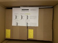
Been through a number of iterations on developing a power amp for my stereo rig - most recently, a few months back I had a thread for a stereo SE amp built around the 807. I got as far as a crude prototype, but life intervened again. In the meantime, I found an eBay auction for an inexpensive pair of Hammond AO-39 chasses. These were reverb amps for the A100 organ, and have a 5U4-based power supply, two 6BQ5s in cathode-biased AB1, and a 12AX7. Hmmmmmm ... a pair of PP monoblocks with a little more power ... Hell yeah, I'm in!

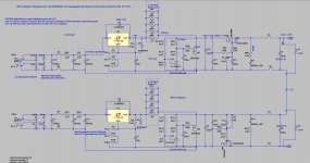
The original circuit is built around a differential input, and is not really appropriate for a guitar power amp in a number of ways, so I designed a circuit with a Fender-esque LTP on the input and adjustable cathode bias for the power tubes. I chose to use the 6P14P-EV in order to run higher voltages (and dissipation, but as we'll see that wasn't an issue), and the 6N2P on the front end because I have a pile of them and I'd rather use my vintage ones in something where they'll make a difference.

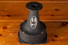
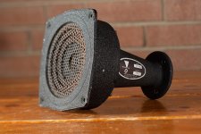
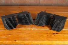
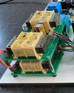
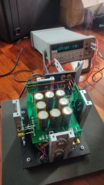
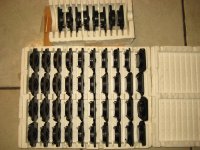
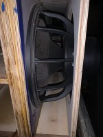
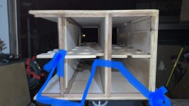
I've successfully built the prototype, and am now stripping the chasses to prep for cleaning and painting. I may or may not reuse the noval sockets, depending on how easily they clean up (and whether I break them in the process).
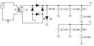
Power Supply

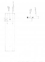
The original power supply ran the rectifier into a dropping resistor and then to a CRC pi filter, taking the B+ from the second filter cap. This is overly complicated for my use case, so I simplified it to taking the B+ from the first filter cap. Removing 250R and using modern wall voltage raised B+ by 55V, to 370V, well within spec for these tubes. I chose 335V for the screen supply based on simulation results, and the the PI is fed a solid 300V. The 6.3V heaters will be elevated from the power tube cathodes. The 5U4 is running well within spec.
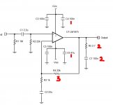
ao-39-2.PNG

Phase Inverter

The PI is a standard Fender LTP. I think I cribbed the values from the Deluxe Reverb? Simulation showed that the 82/100 plate resistors were overcorrecting for the imbalance, so I changed to 91/100 and got very close. I think I also changed up the GNFB values.

There will be a 100k attenuator prior to the blocking cap.

Power Section

Bog-standard shared cathode bias EL84 power section. The only complication I added is a 2W 200R pot so that I can dial in the bias more closely when I change tubes. The pot goes to a 100R resistor to ground for bias measurement. I also added a 100K resistor around the pot for insurance - if the pot ever fails short, this will cut the tubes off instead of letting the bias get too hot. 470R screen resistors simulated the best balance between output and distortion. Oh, and I also built the simulation with a 16R load on an 8R transformer, because the Hammond OT wants a 4R load and I'll be using 8R cabs.

ao-39-1.PNG

The only disappointment I've got is that due to the GNFB, it's got pretty low sensitivity. I may use a pot for it to be able to adjust sensitivity on the fly. OTOH, I'm also using a preamp that can easily drive the low sensitivity if necessary.

Specs:
5.4Vpp (1.9 Vrms, +8dbu) input yields 11W at 1% THD
7.6Vpp (2.7Vrms, +10.8dbu) input yields 14W at 5% THD (just getting into crossover distortion)
Frequency response +/- 1dB from 40Hz to 33kHz (limited by OT - the circuit simulates at +/- 0.5dB from 10Hz to 77kHz)
Output impedance ~1R in the audio range
Plate dissipation at idle: 12W
Screen dissipation at max output (14W/5%THD): 2W

I'll be posting pictures as I go to show how things are progressing. Would love to hear any thoughts on the circuit or the approach!

QUAD 405-2 One Channel down. Help appreciated

Hello
I have a Quad 405-2 with one channel down. One channel works but the other gives a loud mains hum. It is taking about 300 watts from the mains so I am keeping it off.
Does anyone have experience of what are the common faults on the 405-2. I have circuit diagrams and test gear like multimeter oscilloscope and signal generator and have repaired the preamp a few times now.
Help would be appreciated with common faults that give loud mains hum on one channel.

[FS] Wavecor, Faital, SB Acoustics, Hypex PSC

Hi,

Here is the item i would like to sell :

- 4 WAVECORE WF182BD10 SOLD

One
pair for 200€ but prefer to sell the 4 in on time if its possible.


https://zupimages.net/up/21/48/bi63.jpg

https://zupimages.net/up/21/48/3n4h.jpg


- 2 HYPEX PSC2.400 SOLD

400€ excluding shipping.


- 1 HYPEX PSC2.400D SOLD

200€v excluding shipping.


https://zupimages.net/up/21/48/eoxs.jpg

- 3 Sb Acoutics TW29RN-B SOLD
One
item for 100€ but prefer to sell the 3 in on time if its possible.

https://www.zupimages.net/up/21/48/vhmk.jpg

- 2 Faital 6RS140 SOLD
Pair
for 170€

https://www.zupimages.net/up/21/48/an7s.jpg

https://www.zupimages.net/up/21/48/csyl.jpg

Please feel free to ask anything about my stuff.
I am in France, can ship worldwide if needed.

Best Regards

Pioneer SA-510: sound decreases & hum after warm up

Hi starting the restoration of my Pioneer SA-510. After some first checks I hooked speakers and source equipment to this amplifier.

Step 1 - Thorens TD-160: after connecting this turntable, I first tried to play a record. It all went well, in fact it sounded quite good. After playing one side of a LP, I flipped it to play the other side. And as soon as I touched the headshell of the Thorens I noticed a hum/buzz. Also when I touched the tonearm, this happened.
When I dropped the needle, I noticed that there was hardly any sound coming out of the speaker.
FYI; the Thorens TD-160 is not grounded in this setup.

Step 2 - Checks on volume potentiometer: Since this is a vintage product, dirt can be anywhere. So I checked if the potentiometer had dirt causing the volume drop. When turning it up and down I felt it was not as smooth as it can be. But I also tested the volume before it dropped and than the volume knob was working good enough. So I expect the cause of volume drop is not the volume potentiometer.

Step 3 - Check different audio input: Next I connected an iPhone to the aux input. Here I had the same effect; hardly any volume coming from the speakers.

Consideration - I have not yet opened up the amplifiers casing. Though I expect it will be quite dusty inside.

Question - Does anyone recognize this situation?

Playback issues with Denon DN-790R

Hi all, I just bought a Denon DN-790R off ebay and there's a slight issue with it that I was hoping someone could chime in on and help me with?

It plays great once it gets started, but more often than not, on pressing play, it plays without any audio coming through then stops and makes some internal noise, then tries again. It can go through this process up to 3 or 4 times before it plays the tape properly. Once started, it plays fine and passes the audio signal through. I've noticed that the one motor on the right is spinning when it isn't working properly, but is stationary when it is playing properly (and delivering an audio signal). I tried to capture it on video for clarity.
I am wondering whether this is an easy fix or if I should return the deck? I really love the sound quality of it though!

Many thanks in advance for any suggestions!

Login to view embedded media

Solving Port Noise

I've had a pair of Speedster kit speakers in my posession for a few years now. They're excellent nearfield monitors, covering most of the musical range by themselves in a small package. I'm quite happy with them, but as with all things the tinkering began about a year ago. Some pretty serious EQ was brought to bear on these, trimming the excess brightness and cleaning up my room modes/desk bounce, etc. The bass management in particular has become quite cumbersome, totaling 9db of boost and a 4th order cut at 40hz. The frequency response is incredible now. No fatigue, deep resolving bass, no midbass hump, etc. All this boost however has completely overloaded the port at high listening volumes. I'm getting unimaginable chuffing. In the long run, my answer will be to add a sub like the SB3000 Micro.

For now, I'm thinking about replacing the port. In theory, this could be resolved with a simple flare, right? I cut a new port with total length equal to the previous, same diameter, same tuning with less interference, yes?

The next, more extreme option would be adding passive radiators. I've modeled a number in VCAD and my best bet to match the W4-1720 is the Peerless 830880. They do not fit on the back. A full half inch too long, unfortunately. To fit them on the existing enclosure I would have to remove and plug the rear port and mount them on their sides. Not sure how that would affect the sound to be honest. It does remove around 3db from the bass response.

My last, most extreme option would be to recreate the slot port design of the enclosure. I've been considering an enclosure redesign but haven't gone through with it. The slot port has a wider opening, lower tuning, and a broader, lower air velocity peak. I'm not that excited about the front facing nature of the port, either.

I'll take literally any recommendations for how to solve this. Cheaper is better, but I plan to have these for a long time. I could invest in them a bit if convinced.

Some reference material, EQ and VCAD sims are attached.

Attachments

  • IMG_0039.JPG
    IMG_0039.JPG
    357.2 KB · Views: 210
  • Screen Shot 2022-11-04 at 09.48.24.png
    Screen Shot 2022-11-04 at 09.48.24.png
    332.5 KB · Views: 198
  • Screen Shot 2022-11-04 at 09.48.42.png
    Screen Shot 2022-11-04 at 09.48.42.png
    267.2 KB · Views: 187
  • Screen Shot 2022-11-04 at 09.57.20.png
    Screen Shot 2022-11-04 at 09.57.20.png
    435.3 KB · Views: 170
  • Screen Shot 2022-11-04 at 09.59.15.png
    Screen Shot 2022-11-04 at 09.59.15.png
    384.5 KB · Views: 173
  • Screen Shot 2022-11-04 at 09.59.40.png
    Screen Shot 2022-11-04 at 09.59.40.png
    352.4 KB · Views: 199

EQ APO Active XO interfering with other audio/video player

Hi there!

I am new to active XO using a PC ---> 7.1 AVR via HDMI. Using EQ APO with "Peace" GUI. Fairly straightforward.
3 way setup right now using 6 channels on the receiver.

Took 3-4 days of tuning to get it sounding good. I used to use bit streaming before on JRiver for music but I don't think that would work now, I use DirectSound now.
Browser audio works good e.g. YouTube, Netflix on browser etc. (afraid of trying the Netflix app where it uses Dolby Digital)

Now it appears that if I want to watch my favourite show on VLC, maybe VLC thinks a 7 channel surround setup is being used and I can only hear skipped audio. If I select Mono from the right click ---> audio ----> Stereo mode options it works but that's suboptimal at best.

A lot of times where I think it might be trying to play Dolby Digital from a movie or TV Show file it just crashes on start (which has never happened before, ever, in 10 years of usage).

Is there anything I can do to try and make it work better with all audio sources? I would love to have DD on the movie/shows or the Netflix app for example but since that processing happens on the AVR I don't think it's possible anymore with EQ APO doing stuff.

Also for part 2 of this question: I would love feedback on this sort of active XO setup, if I can do it better using different software like rephase or something else. I'm not code savvy though. I've done some measurements and the phase is just crazy. All over the place.

Your assistance is greatly appreciated!
-B

Class D consulting for an old schooler

Hello diy community,

I was one of the many who got hooked by the symasym hype train, soldered a few together and was quite happy about the result.
Very recently, i decided to build a few more amplifiers for center and rear speakers which pulled me back to the diyaudio boards.
Because i can already tick the box at discrete amplifiers ... and the Symasym somehow seems to have fallen out of time, i was now thinking of chip amplifiers....
After a little research, the old known gainclone variants also seem no longer up to date and not really available due to chip shortages...

So class D it is!

But honestly? The whole topic feels like i have actually fallen out of time 😀
Most of the builds i see are made from aliexpress boards with switching power supplies? I even saw some LED PSUs screwed into the case?? Pure blasphemy!!!! 😀
But seriously: is class D too complicated, SMD too small to push for real DIY amplifiers?

Never mind... the whole class d efficiency, available DSP for active crossovers etc. are way too fascinating.

To get started, i would like to build a >3 Channel amplifier with a good value that can outperform or at least keep up with my symasym regarding sound quality.
In addition, i would like to use one of the ADAU1701 boards (tinysine TSA1701) for room correction and crossovers.

There are currently two chips that seem to be en vogue: the MA12070 and the TPA3255
After digging through a few posts and dead aliexpress links, i found some options:

the PL-AD-160 with MA12070 seems to be accepted with the capability of providing 4 (20W) Channels for 50€
https://www.audiophonics.fr/en/ampl...lifier-module-ma12070-160w-4-ohm-p-14732.html

Some wrote, that the TPA3255 sounds better but is more expensive....
but this board right here comes for 30€ (two channels) and is actually affordable as well
https://de.aliexpress.com/item/1005004891306422.html?spm=a2g0o.productlist.0.0.7cec3a64R2jRwy&algo_pvid=15009b9a-fe1b-47a7-8be3-b5011ff84344&algo_exp_id=15009b9a-fe1b-47a7-8be3-b5011ff84344-5&pdp_ext_f={"sku_id":"12000030912292550"}&pdp_npi=2@dis!EUR!44.92!30.09!!!!!@2100bdd516676701151605743ec78e!12000030912292550!sea&curPageLogUid=jUQqLNz7Fk0t

which board should i try?

And what PSU should i take?
I used to solder huge capacitor banks into the PSU etc... can i actually use 24V LED PSUs for the MA12070 without hearing any noise and loss in dynamic sound?
Do you guys have a good value recommendation for me that fits theses lovely class d chips?

https://de.aliexpress.com/item/1005002843829663.html?spm=a2g0o.productlist.0.0.47596d4b4XsFsi&algo_pvid=aef4cdf3-72dd-4a0c-80bc-f487228b0dce&aem_p4p_detail=202211051440373324342316823640002269095&algo_exp_id=aef4cdf3-72dd-4a0c-80bc-f487228b0dce-9&pdp_ext_f={"sku_id":"12000022434674607"}&pdp_npi=2@dis!EUR!8.39!3.77!!!!!@0b0a050116676844378256993e414f!12000022434674607!sea&curPageLogUid=kJsyApIyCJ6B&ad_pvid=202211051440373324342316823640002269095_2

I would be really grateful if you could walk me a little throu all the options, chips boards etc.
Thanks alot!
Samuel

Another “What are these?” Thread

So I’ve already searched for eminence 15” vented aluminum dust cap and the numbers on the back with no luck. Guessed at Eminence as the “67” suggests they we the source, but no other reason to assume it. Any ideas?

Attachments

  • 115E8F95-8D45-4D2E-940B-55BF51340325.jpeg
    115E8F95-8D45-4D2E-940B-55BF51340325.jpeg
    377.9 KB · Views: 114
  • 3BEBB0BF-3507-42A1-B0B2-4A8AD70F6379.jpeg
    3BEBB0BF-3507-42A1-B0B2-4A8AD70F6379.jpeg
    656 KB · Views: 118
  • 3D834E18-876E-4387-BBAF-BCB5D072027B.jpeg
    3D834E18-876E-4387-BBAF-BCB5D072027B.jpeg
    340.4 KB · Views: 109

*Brand New* ETI Research KRYO Connectors. Binding Posts, Bananas, RCAs, Spades.

For Sale: All Brand New ETI Research Kryo Connectors:

8 Sets of Kryo Binding Posts
(2 pairs per set) -- $100 Per Set. (MSRP is $200+)

9 Sets of Kryo Banana Plugs (2 pairs per set) -- each set includes small and large housing to use with different diameter cables (see photos) -- $85 Per Set (MSRP $150+)

2 Sets of Kryo Male RCA connectors (2 pairs per set) -- $100 Per Set (MSRP $200)

1 Set of Spade Connectors (2 pairs per set) -- $85 Per Set ($200 MSRP)

More details available here: https://eti-research.com/kryo-connectors/

Priced to sell quickly. Discounts for multiples. PM me with offers.


Paypal Preferred.

Attachments

  • ETI-Research-Kryo-Banana.jpeg
    ETI-Research-Kryo-Banana.jpeg
    69.4 KB · Views: 215
  • IMG_6079.jpg
    IMG_6079.jpg
    519 KB · Views: 218
  • IMG_6080.jpg
    IMG_6080.jpg
    545.7 KB · Views: 235
  • IMG_6081.jpg
    IMG_6081.jpg
    475.5 KB · Views: 230

minimum capacity and impedance cables

Hi Friends,
I am looking for cables to connect the amplifier to speakers with minimum capacity and impedance. I have an amplifier from the Polish manufacturer Baltlab which works best with the Red down Nordost. however, they are too expensive for me. is there any cheap alternative? the amplifier is very neutral and every change of cabling makes a difference.
I will be grateful

Audax HD20 B 25 H driver repair / CELEF STUDIO PROFESSIONAL TRANSDUCER

Hi everyone,

I attach a few photos of these beautiful drivers: here serving the midrange in some recently acquired CELEF Studio Professional Transducers. I have found a couple of other threads relating to repair of these drivers (and also in connection to these same CELEF models) here and on AudioKarma where owners have problems with the early-model surrounds shrinking. Thankfully, mine have the later PVC surrounds which still seem to be going strong. However, you will see in the photos that the very outer surround ring is coming away in a few places from the PVC surround. There is not a great deal of driver movement at this outer edge and therefore I assume I can glue them back down? The surround seems to be made of paper/card.

Can anyone recommend an appropriate glue? I assume something such as the glues available here be suitable?

My other question is about the little nodule of PVC in the first image -- I wonder if this has actually unseated the glue? would it be foolish to try and remove this before sticking down the surround? Maybe it would be better to just attempt to cut out a tiny notch in the outer card surround to fit around it? I don't see the same thing on the other driver (there is a little one but it's not impacting the surround). Are these caused by the mold during production of the surround? it will make sticking the surround back seamlessly impossible.

I am also interested to hear from any fellow, knowledgeable CELEF owners. Unlike the other examples of these drivers discussed these do not have Stuart Tyler's 'modifications' -- which seems to amount in other examples to AT LEAST the addition of cork to the spider (?) and a CELEF sticker covering the back of the magnet. Mine have no such cork and no such sticker... the Audax name and model number is clear. I don't know if they dropped these 'mods' in the later production of these speakers -- although I don't believe that many sets were ever produced. Anyway, would be interested to compare notes on this with any eager parties 😉

Anyway, thanks in advance for any input anyone might have!

I have only had time to listen to these speakers briefly, but they sound absolutely stunning...and that was a quick test of each alone....who knows what the stereo pair might achieve!

Nick

Attachments

  • celef 1.jpg
    celef 1.jpg
    346.9 KB · Views: 167
  • celef 2.jpg
    celef 2.jpg
    559.1 KB · Views: 234
  • celef 3.jpg
    celef 3.jpg
    413.2 KB · Views: 187
  • Like
Reactions: eschenborn

How to anneal 5 micron aluminum foil ?

I have been working on 1" ribbons for several months using 6.5 micron foil in the protypes. The problem with this foil is that I can't hold a close enough width tolerance (.004 or so) while slitting a 6' length.

I located a very small roll of 1" by 5 micron precision slit foil (exactly what I ultimately want to use) and have been hoarding it for the final ribbons...which were finished yesterday.

New problem. This foil is either treated differently, or a different alloy such that it seems very brittle and has a tendency to break during pleating.

Does anyone have any suggestions on how I might go about annealing the 5 micron foil?


An externally hosted image should be here but it was not working when we last tested it.

Which homebuilt streaming option (Amazon HD, Spotify and Internet radio) using RPi4

Hi All

I am looking to build a streaming setup, I already have an RPi4 along with a Khadas toneboard as a dac. I also have a Rpi4 touchscreen.

I do not have a large local digital music collection, and will mostly stream via Spotify or Amazon HD, along with radio stations.

So, what is the best software to use a streaming option? I recall Volumio and Moode being good options, is this still the case?

thanks.

Attenuation After Noisy Preamp?

I built a VTA SP14 preamp which generates a 55dB 120 Hz hum a few inches from the woofers. That hum is audible at the listening position. This occurs when I use the SP14 with either a 200 or 400 watt solid state power amplifier driving 96 dB efficient speakers. If I use the SP14 with a First Watt M2x which is only 25 watts the hum is barely audible. I built the SP14 to use specifically with the Peachtree GaN 400 so the hum is a problem.

I have done everything I can with the SP14 to eliminate the hum which presumably is coming from some sort of ground loop or perhaps just a faulty design. The level of the hum is constant regardless of the volume control on the SP14 or the input from my DAC or anything else I change including wiring, transformers, or grounding so I have pretty much exhausted my options there and VTA doesn't have any suggestions.

It seems to me it should be possible to manage the hum by attenuating the output of the SP14 Preamp either before the GaN 400 amplifier or after the GaN 400 and before the speakers. But nobody seems to do this. In researching the problem it appears that the issues of attenuating after the preamp have to do with impedance, damping and distortion.

Does anybody have any suggestions about the best way to attenuate the output of the preamp to make the level of the hum inaudible without changing my power amplifier or speakers?

Thanks.

  • Locked
Open baffle design advice for Lii Audio F-15

Hi,

I am looking at building some open baffle speakers with the Lii audio F-15s and am trying to decide on baffle dimensions. I will be listening quite nearfield and am limited on space between the sidewalls, although have plenty above and behind me. so I was thinking of a baffle size of 70x75x4cm. Ideally this would be smaller, something like 60x65x4cm.

Would there be an appreciable difference in bass response between these two baffle sizes?
Also, is it an issue to mount the drivers centred and the baffle is almost square. Is this of any detriment, is it better that they are off centre? Would that make an appreciable difference nearfield?

I plan to add a sub later on, and don't need thunderous bass. In this setup I'll mainly be listening to jazz, soul etc.

Thanks in advance for your help.
Quick mockup attached of the two sizes for comparison


Screen Shot 2022-11-02 at 2.23.23 pm.png

50ohm traces?

So I want to have a oscilator driving a buffer/fanout IC to drive the SMB connections out to other components. 24.576MHz so not GHz but the design sheet recommends a trace designed for 50ohm impedance.

Do i simply layout and then adjust the thickness of the trace based on a calculation to adjust the trace width based on weight, thickness and length?

The only other way is to connect with a resistor in the way rather than trace (tune the wave guide?).

7119932F-0543-466D-BA4F-92A18AF750A3.jpeg

Newby question: What is grid current and how do I measure it?

Reading here I here people speak of this thing called "grid current". What is it? I understand its current and varies based on ohms law like any other current. It must be very small as the grid basically floats in the space charge right? It has no resistor across it to draw current. Maybe if a tube is gassy that might be like a resistor that would cause the grid to draw current?

Also on the breadboard how do I measure such a small thing as grid current without having the measuring instruments itself throw it all off? Certainly the sense resistor method wont work by measuring the voltage drop across a grid stopper, seems like it would be an impractical way to measure it, the resistor would have to have ultra-precision right? I have this 100 uA full scale analog microammeter, in bygone days would people measure grid current by simply hooking a microammeter in series with the grid? If so, should it be hooked up on the input or output side of the grid stopper? If so, what polarity to hook it up? If so, should I maybe pick up a 50 uA full scale microammeter for better accuracy? If so, Should I pick up a center needle 50 uA meter so I dont have to consider the polarity hooking it up?

If these are too-many stupid questions please set me straight on the practicalities of measuring grid current 🙂


100 uA Meter.jpg

Software DSP

Hello! I am trying to make a software DSP for WAVE PCM sound format (16 bit). The DSP will have the following functionality - change the signal level, add delays and change the frequency. I first started by changing the level by multiplying the bytes with constant, but that didn't work correctly. Here is a picture of what happened:


Update: I find the solution, i was using wrong type variables.

Regards!

Boston HD7 (HD5?) repair or cabinet salvaging

Hi,

Background
I've been given a pair of Boston HD7 in a not very decent condition. Tweeters (and maybe woofers) had been changed, don't know about the crossovers. See pics. Sounds better than expected but highs are metallic and sibilance + hissing are very prominent. Also not much bass (that might be already the case when new, since it's a small woofer). It is a sealed cabinet, external measurements are (aprox) W225 H 355 D 180 mm which is weird because it doesn't match the specs of the HD7 but the HD5. Thus the ? in the title.

Question
What can I do with these?
  1. Change drivers and XO. In that case, could I have some suggestions? I live in Europe (no Parts Express).
  2. Get rid of everything and get a new set of speakers, it will be difficult to find drivers for that "small" sealed enclosure
  3. Other
Thank you for any help
Sergi


IMG-0276.JPG
IMG-0277.JPG

Various JBL professional horns

I have to sell various Jbl professional series horns:
n.1 Jbl 1217-1290 €.50
n.2 Jbl L91 lens €.400
n.2 Jbl 2329 adapters €.150
n.1 Jbl 2330 adapter €.50
n.1 Jbl 2365 €.90
Prices doesn't include shipping. Payment through Paypal

Attachments

  • DSC_0457.jpg
    DSC_0457.jpg
    189.3 KB · Views: 100
  • DSC_0458.jpg
    DSC_0458.jpg
    149.3 KB · Views: 93
  • DSC_0459.jpg
    DSC_0459.jpg
    170.5 KB · Views: 101
  • DSC_0460.jpg
    DSC_0460.jpg
    149.7 KB · Views: 101
  • DSC_0461.jpg
    DSC_0461.jpg
    156.5 KB · Views: 105
  • DSC_0471.jpg
    DSC_0471.jpg
    214 KB · Views: 98
  • DSC_0472.jpg
    DSC_0472.jpg
    214.2 KB · Views: 96
  • DSC_0474.jpg
    DSC_0474.jpg
    176.6 KB · Views: 93
  • DSC_0476.jpg
    DSC_0476.jpg
    195.6 KB · Views: 95
  • DSC_0482.jpg
    DSC_0482.jpg
    279.9 KB · Views: 94
  • DSC_0483.jpg
    DSC_0483.jpg
    208.1 KB · Views: 88
  • DSC_0485.jpg
    DSC_0485.jpg
    220.6 KB · Views: 92
  • DSC_0489.jpg
    DSC_0489.jpg
    128 KB · Views: 88
  • DSC_0491.jpg
    DSC_0491.jpg
    143.3 KB · Views: 103
  • DSC_0492.jpg
    DSC_0492.jpg
    274.8 KB · Views: 93
  • DSC_0494.jpg
    DSC_0494.jpg
    161.2 KB · Views: 94

Custom Built Speaker Cabinets

I built these cabinets to be used with Eminence 10" coax driver, BETA-10CX with Eminence F-110m-8 compression tweeter......But could be used with many other 10" woofers and cut in a separate tweeter. The cabinets have built in, two way crossover, PRV Passive Crossover !DF1800H / 1800hz with full controlls on back of cabinet. Extremely heavy construction, prewired with OFC wire. Can not ship. Must pick up south of Boston Massachusetts. $100 for the pair.......see them here: contact me at... rvb100 at comcast dot net Roy

https://public.fotki.com/Rbertalotto/hifi-stereo-stuff/10-custom-cabinet/

Searching for the best EMI/DC filter

Hello, im wondering if some of you guys compared EMI / DC Filters and can suggest some, im trying to build a diy power distributor for relatively cheap (but still trying to make it "high-end" in terms of components and filters)

i found these two which look quite High End and im wondering what "experts" think about it
https://www.thel-audioworld.de/module/Netzfilter/Netzfilter.htm
https://775mv.com/product/power-emi-filter-for-audio-12a/

also i have a question:
is it worthwhile to put 1 central DC Filter and 1 EMI Filter for each socket (and between each emi filter a ferrite choke) or would it be enough to make for example one "Rail" for analogue and one "Rail" for digital devices?

Bruno Putzey balanced pre pcbs full set, smd components pre solderdd

FS a full set of Bruno Putzey balanced pre pcbs all smd components pre soldered. Includes hypex regulators

Group buy and information in this thread

https://www.diyaudio.com/community/threads/bruno-putzeys-balanced-preamp-group-buy.279981/

£80 plus shipping anywhere in the world

Attachments

  • 20221107_123900.jpg
    20221107_123900.jpg
    420.7 KB · Views: 194

Negative resistance better than current source for MOSFET follower amp?

Often in a source follower amp cct you put in a constant current cct to pull the signal the other half of the cycle. If the amp is driving into an open circuit "load" the output mosfet is very happy because the drain current stays constant for the whole of the cycle and so the source voltage tracks the gate voltage almost perfectly. Now if we attach (for simplicity) a resistive load then the load current varies durning the cycle and so the mosfet introduces some distortion because the now varying drain current means the source voltage doesn't perfectly follow the gate signal voltage any more.

Would it not be better to make the constant current circuit instead a negative resistance circuit (not very much difference) so that for example, as the signal swings positive and the load current is increasing the CC cct is decreasing at the same rate? So make the CC cct negative 8 ohms. That is, for every 8 volts increase across it make it decrease it's current by 1 amp and vice versa. This way the output fet sees a more or less constant current during the cycle and distortion would be very low. As the fet Vds reduces on signal peaks and it's ability to pull current is reducing, the negative resistance cct is easing up as well instead of holding on tight for no good reason. Of course, if all this was applied to a real world loudspeaker load, the wheels might fall off the whole idea. I don't know. What do you think?

GP.

For Sale THE WIRE Modules SE-SE, BAL-BAL, PSUs + SOA-2.V3 + extra parts

1x THE WIRE PSU 15V 15V
50.-€

1x THE WIRE PSU 12V 12V
50.-€

1x THE WIRE SE-SE (gain = 1)
40.-€


2x THE WIRE BAL-BAL (gain = 1)
50.-€ each

Some SMD resistors to change output voltage of PSU
105k 15x
162k 5x
1.24M 6x
1.5M 3x
If sold as a whole, the resistors are included

1x SOA-2.V3
A balancing amplifier with gain as an ideal addition to the BAL-BAL module.
https://funk-tonstudiotechnik.de/SOA-2.V3-neu.pdf
The document is only available in German.
50.-€

The above preferably as a complete package with discount.


16x LME49600
bunch only
45.-€

7x TPS7A33 regulator
bunch only
35.-€


All prices plus shipping from Germany

Regards Martin

Attachments

  • W1.jpg
    W1.jpg
    621.3 KB · Views: 190
  • W2.jpg
    W2.jpg
    276.9 KB · Views: 189
  • W3.jpg
    W3.jpg
    536.5 KB · Views: 193

For Sale Esotar 2 & scanspeak tweeters

A pair Dynaudio Esotar 2 from C2, clean and mount round faceplate, 110mm Dia. - 800 USD + ship
Few pairs of Scanspeak OEM sharp nose tweeter, up to 40khz , 104mm , 4 ohms ,25w -155 usd pair include ship to general area

Paypal only.

Attachments

  • 1.jpg
    1.jpg
    214.5 KB · Views: 277
  • 2.jpg
    2.jpg
    160.4 KB · Views: 207
  • 3.jpg
    3.jpg
    106.6 KB · Views: 190
  • 4.jpg
    4.jpg
    162.4 KB · Views: 216
  • 5.JPG
    5.JPG
    14.5 KB · Views: 190

effect of power supply / ground loss on amplifier

Hi folks,

I like to discuss with you what happens to an amplifier in case either the positive or the negative power supply is lost or the ground is disconnected.

I recently figured out that my amplifier evaporates the magic smoke in case the negative power supply is disconnected and this is why I start the discussion.
After spending some time at the bench doing an autopsy, I went back to circuit simulation in order to figure out the root cause for some components destruction. I observed that once any power supply gets lost, my amplifier no longer works at all and operating points shift so that components get destroyed.

I don't like to bore you with my specific amplifier, but like to discuss amplifiers in general.
I need you to get my thinking straight, which went in confusing loops throughout the weekend.

Actually an audio amplifier is just a huge op-amp. Many op-amps support single supply operation and I believe an audio amplifier should support this, too. At least not burn down in case it happens (like a fuse blows). My expectation would be that ideally the output DC offset is half of the supply voltage and the signal is reproduced around this offset.

It believe it should be avoided that any unconnected power supply input is undefined floating around.
So my first idea was to connect diodes to ground so that there will be a path for the current (see ordinary diodes in the schematic).
This probably is a good idea.
In case either power supply gets lost, it will be clamped to a diode drop above or below ground.

Also, a pair of resistors in parallel to the diodes form a high impedance virtual ground in case of ground loss. May be good, too. However, this virtual ground would be a diode drop away from one of the power supplies in case of loss of the opposite power supply.

During the investigation I found out that in my amplifier all circuit blocks (CCS and current mirror) defining DC points are no longer functional once any supply or ground is lost.
This is partly because I was lazy connecting references to ground because having a ground plane makes this easy (case A in the schematic). bad idea obviously.

Most designers are using connection scheme B, which is independent of ground - far better than what I did.

Scheme C is also interesting, but has the disadvantage that power dissipation is doubled and components like transistors need to withstand twice the voltage.
However, I found out that this scheme is beneficial in some cases where scheme B would not work. It makes operation more independent of each other.

My observation so far is that some circuits may behave in a very unforeseen way.
The diodes avoiding floating supplies seem helpful, but still some circuits behave strangely.
For example the current mirror with EF helper transistor behaves strangely in my amp with only one power supply. This is having to do with the helper transistor. A plain CM or Wilson CM instead works well.
Also, the cascodes of the CCS no longer work as cascodes, but become diodes instead sometimes and all kind of other freaky things going on.

What do you think?
Do you consider power supply or ground disconnection in your designs?
How do you handle this?
What do you think about my observations and ideas?

Here is the example schematic showing some CCS I use to help me thinking:
power_supply_loss.png

LM1875 Amplifier - Change in Component values.

Hi I am building LM1875 amplifier, Transformer Will be 18-0-18V and source CD Player (Occassional Phono Pre). I understand lm1875 IC Datasheet has standard values for broad application. But I wanted to know in Chipamp.com BrianGT schematic (See pic attached) why values of
1) C4 and C6 values are 0.1uf and 47 uf instead of standard 100uf and 100uf*
2) Zobel network R5 and C7 are 2.7ohms and 0.1uf instead of 1 ohm and 0.22uf **
3) feedback resistor R4 is 22k instead of standard 20k.

*Powersupply will probably be with snubber capacitors and MUR860 diodes. Do suggest what type of capacitor will be good.
**my speaker wires will be short and speakers are not decided. Probably wideband.

power supply schematic also attached.
Thanks and regards

Attachments

  • LM1875.jpg
    LM1875.jpg
    97.7 KB · Views: 492
  • ps.jpg
    ps.jpg
    58 KB · Views: 415

Effect of harmonics' phase on perceived sound

Hi,

reading documents by Nelson Pass I've seen that most of the people like a negative phase for the 2nd harmonic, explaining it with the fact that it will counteract the inertia of the speaker, but... what about the phase of other harmonics? Need to be as close as possible to zero?

Anyone has direct experience on it or literature to link/attach?

Thank you in advance
Roberto

Hypex Modules NC502MP 2x350W + NC500MP 2x250W brand new.

Hi,

Having abandoned a multi-channel amplifier project, I am selling my Hypex Ncore Module NC502MP


Like new, tested with my DY Project.

  • Free Cables set
  • Shipment to Europe only


Hypex NCore NC502MP twin Channel Module
PSU SMPS integradted 1200W
Nord Switchable RCA-XLR input board
Auto sensing 100-240V mains input operation
0.5W standby operation
1.5KW Main PSU
47K Ohms Input Impedance, low output impedance
THD 0.0018%
S/N Ratio 116dB
26dB Voltage Gain
1X1200W 8 ohms bridged
2 x 350W 8 Ohms
2 x 500W 4 Ohms
2 x 450W 2 Ohms
Fully loaded flat frequency response
92% efficient

Silent transformers for use in preamp

Hello,

I currently have 4 Hammond 229C30 pcb transformers used in the PSU of the line amp. When the preamp is turned on, one can clearly hear the transformers humming.
- These transformers are 24VA each, load for each xfmr is about 10VA.
- See picture of how the assembly looks like. Bottom PCB is mounted to preamp chasssis used damped (rubber) distance holders.
- Downstream of the preamp is a mains filter with DC-blocker installed.

I'm looking for better alternatives than the Hammond 229 series. I've read on this forum that also other users of these 229 series experience mechanical humm.

Dual bobbin is proposed to be ideal in low power equipment, where toroidal's are not due to too good coupling between primary and secundary.

1. Block Low profile - FL series : https://www.block.eu/en_EN/products/transformers/pcb-transformers/
2. Toroidy Supreme audio toroidal: https://sklep.toroidy.pl/en_US/c/Toroidal-transformers-SUPREME-AUDIO-GRADE-V2/99
3. ??? other, better ideas?

Attachments

  • 229C30 assy.JPG
    229C30 assy.JPG
    46.7 KB · Views: 266

How to find any post by only the post number?

The new platform doesn't allow search just by the post #.
I have many posts (links) from the old platform saved by the post #, like:
https://www.diyaudio.com/forums/showthread.php?postid=1206887#post1206887
The links to these posts do not work:
1667578674582.png


Doing this through the "Advanced Search" is very laborious and not always productive. I think there must be an easy way...

DIY Servo driven Linear tonearm

I have been experimenting with LT tonearms over the past 6-8 months, and have built 2 different LTA's with 4 different carriages. During this process I have learnt that a short stiff carriage/armwand is what is needed.

LTA 1 - Built as a proof of concept. This was about as good as my reference arm a Technics EPA100. Bass response was better and noise floor slightly lower. It struggled with stock bearings to track the Stanton 881s so I increased the diameter of the wheels which made a huge difference. Changed to my Technics EPC205mk2 with a Jico SAS.

LTA 2 - This is a total rip off of the Clear Audio TT1 and Niffy's carriage (the FROG). What this does amazingly is lower LP surface noise to levels I have never experienced, detail and dynamics are fabulous. Its issue is tracking off centre pressings where the voice has a lot of energy, I can hear distortion in each channel as the carriage moves back and forth. I built another carriage this time 20g lighter. This new carriage still has distortion on very heavily modulated tracks on the test LP, but I haven't heard it on music yet. It sounds great, but does have higher surface noise.


The reason I started this thread is I am considering building a motor driven LTA and I'm looking for others thoughts and ideas.

Goal is to duplicate LTA 2's FROG performance without the distortion tracking off centre pressings. Is this even possible

First decision is either mechanical servo like the Rabco or use an Adrino robotic controller?

Arm will be split effective mass like the Dynavector DV505. Main arm to be large and rigid with horizontal bearing and secondary arm on the end with vertical pivot.

Technics SL1200 bearings can be used for both pivots.

Carriage will run on 2x 8m linear rails in brass/bronze bushes.

Drive will be toothed belt driven by O rings

Drive motor 12V geared run at lower voltage to keep noise low

Attachments

  • img058.jpg
    img058.jpg
    153.6 KB · Views: 1,044
  • P_20200101_121545.jpg
    P_20200101_121545.jpg
    504.7 KB · Views: 1,097
  • P_20200627_124044.jpg
    P_20200627_124044.jpg
    599.7 KB · Views: 1,020
  • P_20200713_094244.jpg
    P_20200713_094244.jpg
    664.4 KB · Views: 968
  • P_20200616_153223.jpg
    P_20200616_153223.jpg
    470.8 KB · Views: 931

Rockford Fosgate Punch 45HD

I have more broken amps than working amps so it's time to try to fix them. I think this one might be the easiest to fix.

I can't remember what the symptoms were but it started obviously not sounding right. When I picked it up I heard a rattle. I opened it and a tiny cap was loose.

Anyway, on this small board these tiny caps (circled in red) have come off (this isn't my pic but I took it and highlighted the caps, as they are not there on mine).

The contact points on the board don't even look metal. I'm looking for guidance before I try anything because I don't want to screw this up. Can I just try to solder the caps back on? I'm not sure I can even do it, it's so tight in there. Thanks for any input you may have. I'd like to save this amp, if possible.

I went and took a pic of mine and attached it also.

edit: Just ran across a video and learned some new information. That board is the HBPIM board. Any idea where I could get a replacement of that?

Attachments

  • rf_punch45hd1.jpg
    rf_punch45hd1.jpg
    389 KB · Views: 401
  • 20150607_105704.jpg
    20150607_105704.jpg
    485.4 KB · Views: 357

JBL E145 3-way with Audax and "help" up to 100 hz

Have a few pairs of old nice JBL laying around, 2215h, 2235h and E-145.

Also last year have build 6 peerlees xxls 830847 16 ohm in ca 100 liter each in paralel ( 3 each side), now is my stereo set-up.
Thinking of use the JBL E145 as mid-bass from 100-600 hz, and Audax HM130Z0 and Viawave SRT-7 as MTM.

Around 96 dB sensitivity.

Here is my xover in XSIM, anyone seeing something wrong or maby have a easyer way building the xover ?
JBL project.png


Best regards Jawen

48pcs Miller & Kreisel 17500 8Ω silk dome tweeters

I bought these probably 15 years ago for a line array project that never happened. Don't even remember what I paid for them. I think they were "working pulls", but they all look new except for some with misshapen gaskets on the back that just need massaging.

Some of these have recently sold on ebay for $26 a pair + postage. I don't want anything near that for them.

Make me an offer for the whole lot, US only.

Attachments

  • MK1.JPG
    MK1.JPG
    507.3 KB · Views: 153
  • MK2.JPG
    MK2.JPG
    650.1 KB · Views: 154

For Sale JVC RC-EZ51 (Shigaclone Donor) Complete with Remote - UK collection

A spare RC-EZ51 I did not use.
It was bought second-hand so has a few scrapes, but I just gave it a spin and all appears to be working (except cassette!) including the remote.

I don't want to extract the CD player parts as I did this to a previous one & it stopped working for some reason!

Asking a modest £15 for this, so someone local (Northants area) to collect would be ideal.

JVC RC-EZ51_Img1.jpg

FS SE 6.1K OPT Transformer Monolith Magnetics S15 new pair! perfect for tubes 45,PX4,2A3,AD1...

hi all, Selling the following:

- pair of SE 6.1K OPT Transformer Monolith Magnetics S15. Both transformers are heavy duty and new.

Version: Hi-B grain-oriented FeSi dual C-core, air gap for 55mA. perfect for tubes like 45,PX4,2A3,AD1....

Datasheet: https://www.monolithmagnetics.com/s...70 single ended output transformer prelim.pdf

Items are located in Germany and will ship in EU.

--850€-- shipping included

payment via paypal (pay for friends) or bank transfer

Attachments

  • 1.JPG
    1.JPG
    569.1 KB · Views: 161
  • 2.JPG
    2.JPG
    587.8 KB · Views: 176
  • 3.JPG
    3.JPG
    367.4 KB · Views: 193
  • 4.JPG
    4.JPG
    374.6 KB · Views: 192
  • 5.JPG
    5.JPG
    379.2 KB · Views: 177

Ian Canada Station PI with Power Management

Hello everyone,

I am currently running a Raspberry Pi with a Stereo Audiophonics ES 9038 DAC. The power comes from an Audiophonics power supply and is routed to the Raspberry via an Audiophonics power management module. This makes it possible to safely switch on and shut down the Raspberry like an ATX switch on a PC. The music is output to the speakers via a Marantz SR 8015 (dual mono). Now I would like to build a new device and have ordered the parts described in the picture. The power management module controls the raspberry via the GPIO pins 04, 17 and 22. Is it possible to do this when the raspberry is installed on the station Pi, e.g. via the GPIO bar J2 of the FifoPI.

Thanks in advance for your help.

Greetings from Bonn, Germany

Bodenplatte 2-page-001 (2).jpg

Shunt regulator design: shunt VS load current rule of thump

Hello,

Don't seem to find much info on this.

I'm currently using shunt regulators (in combination with serie regulators) as PSU for my preamp. As the dissipation is too high for me to feel comfortable I was wondering to maybe leave this out. According to LTspice, it has no added value in suppresion below 1Khz.
Shunt current is 75ma, load current is 160mA (with max ripple of 2mA).

As I have 4 of these shunt regulators, it saves me more than 8W on dissipation.

What is a good rule of thump of the factor between shunt and load current, to have decent added value of the shunt regulator?

Any references to read?

Thanks
Ben

Attachments

  • PRE PSU.JPG
    PRE PSU.JPG
    126.9 KB · Views: 271

What happens when you run a driver at it’s resonance frequency

So can people please advise on the implications of running a driver be it woofer or mid or tweeter or compression driver at its resonant frequency


Just trying to learn further and understand so a few questions please

A driver Driven at its resonant frequency give or take +/-

1 Can or will damage be expected provided it receives low voltage and not overdriven in excess

2 if the driver been driven encounters higher dB feedback will an amplifier compensate re damping..?.

3 same question as number 1 and number 2 ..but if it was a compression driver would things be different as compression drivers can go low but with higher sensitivity ie 106db vs 85db etc

So in a nutshell can a sustained frequency be amplified without redress.

There’s got to be advantages or disadvantages of doing this thoughts please

4 Can the resonant frequency of any driver be found without parameters ie frequency sweep multimeter

YAMAHA B1 AMP 2SK77

HEY I got one of thoses old/rare YAMAHA B1 stereo natural sound amplifiers that I may want to get rid of. Of course the red overprotection light comes on and no sound comes out but the METERS sure are pretty (yes the UC-1 unit). It handled a lot of great gigs at all the big places in Hollywood back in the 70's....sound incredible and VERY QUITE when it comes to noise.
I'm about to take it over to the local YAMAHA wiz and see if he can find the problem or at least tell me if the VFETS ARE good.
Any help out there?

Something cool for Raspberry Pi/ODROID: I2S/DSD isolator HAT with native DSD decoder

IsolatorPi,something cool for Raspberry Pi/ODROID: I2S/DSD isolator with DoP decoder

I designed a Raspberry Pi I2S adapter a couple of month ago and shared many PCBs for free with this DIY community. http://www.diyaudio.com/forums/digi...mate-weapon-fight-jitter-371.html#post4429205
It was really nice. Community members and I were very happy with it. But I’m still worried about sharing noisy PC ground with audio system.

Another thing is that I'm very interested in playing native DSD music through Raspberry Pi. I’ve heard that the latest version of MPD already has native DSD support. But after downloading the software, I was very disappointed to find that the native DSD is only supported over USB interface. This has also been confirmed by Tim. It means the native DSD feature works only with a USB streamer for now. However that's not the way I use a PRi.

And the third thing is the ODROID. I bought a C1+ because a friend of mine recommended. It has a dedicated I2S port (which is incompatible with PRi). It also runs faster than RPi. I'm quite happy with it. The only issue is that none of the RPi audio gears will work with ODROID because of that I2S port.

So I came up with a new idea: An I2S/DSD isolator HAT with optional native DSD decoder for Raspberry Pi and ODROID.

It will have following functions:

1. To isolate ground and all other signals between RPi/ODROID and audio system.

2. Compatible with both RPi and OROID.

3. Supports native DSD playback by plugging in an optional DSD decoder daughter board. The daughter board will convert DoP stream back into native DSD stream bit-perfect at real-time. In this case, all current SD image such as Volumio, MoodeAudio, RuneAudio, and most others, will have native DSD play-back features.

4. Raspberry Pi DACs and other audio gears will work with ODROID (may need software support for configuration).

5. Has isolated I2C control bus for RPi DACs, as well as optional I2C EEPROM ID bus. It will work very well with all RPi DACs and other audio gears by flowing Raspberry Pi HAT design specification.

Since I'm working on multi-channel I2S/DSD FIFO PCB, hopefully I can place a bulk order.

Here is the block diagram. I will be finishing up this project soon.

Ian

IsolatorPiBlockDiagram
by Ian, on Flickr

A very simple "RONIN" amplifier

I want to offer you such an amplifier As a good replacement for the 3886 and 7293 microchips, which have become much more expensive. instead of 240/9240, you can use a very cheap 510/9510. In a differential cascade with a different correction, bipolar transistors can also be used, as cheaper and more accessible. In general, the spice model is below, pdf with a diagram and a *.Ley for ordering or reworking for yourself.
PS ^ I really want to know your opinion, it is dear to me.

Attachments

Mismatch between trafos- acceptable?

So i built a gainclone monoblocks with same exact everything between two units but one channel was humming through the speaker while the other was dead quiet. It turned out to be magnetic coupling of the trafo which i was able to solve by slowly rotating the trafo and my ear to the speaker until the hum went away. The trafos are vigortronix todoidal.
Heres where my gripe starts. As a test i also began rotating the trafo on the other channel and it too had a position where it could induce hum to the amp. But that position differs between trafos by about 40 degrees! Which means the windings between the two units are uneven, even tho they are of the same model and was bought together.

Are such deviations in their windings acceptable?

Displayport out to HDMI in for multichannel audio

Hi there,

So far I have been experimenting using EqAPO as a multichannel loudspeaker crossover on a laptop with HDMI out to a Marantz 7.1 Receiver with HDMI in. The laptop is aging, and could fall apart any day now. It looks asif more PC's and laptops use Displayport out instead of HDMI.
Could Displayport out also be used for 7.1 -filtered- audio channels out, or do I need some convertor?

Goldmund Studietto with T5 arm manual on hifiengine

Someone can download the manual for the Golmund Studietto with T5 arm for me on vinylengine please ?
I can no longer access my account or open another one on their site.
I have just recovered this vinyl turntable literally in pieces that a former customer bought on the internet and the seller sent the turntable as is without clamping it or securing it, so I will try to rebuild it, starting with the arm and the belt.
thank you in advance

A digital audio stream feeding 'almost' directly a Class-D driver & output stage?

Note to Readers: (added on the 31st, Oct 2022)
Please note, this thread should be considered as a discussion only. As it evolved it cannot give working ideas as to how to implement completely digital drives for Class-D.
--------------------------------------------

I do not know whether someone has already done this, but logically and technically, it seems possible.

Suppost a digital stream similar to that used to drive DACs is fed to an algorithm running on a microcontroller or small processor. The algorithm would use extrapolation to calculate the value of the instantaneous voltage at points which are not covered by the data from the stream. These calculated values/data would then be used to calculate the pulse width to feed the driver of the output stage. This would still result in an audio output, but without a DAC.

Learning Bookshelf+Subwoofer Pros and cons ?

Hi all,
comparatively ready 3 way speaker choices are limited (either expensive or one has to buy floorstander) So I was wondering...
1) what are technical disadvantages of having a bookshelf with subwoofer ?
2) If bookshelf measurements are available, can a passive crossover be made to match that bookshelf speaker with DIY passive subwoofer ?
3) (vague question) I know it depends on driver, speaker design and personal volume level preference, but what is very broad consensus on a typical 8 inch driver low end extension and levels achievable ?
thanks and regards.

MMats Hifi-6150D blown MOSFETs

Hello, I'm new here and this is the first amp I will try to fix. I have SMD soldering and development experience but this is my first time working on an amplifier. Here we have an MMats 6150D, it was working fine before but it let the magic smoke at random once. I opened it up and noticed this:

Clearly, a MOSFET died
SYdw0EG.jpg


I took out the clamps and noticed that 80% of the MOSFETS cracked or burnt on this rank of fets alone, all the other MOSFETS around the amp seem fine.
GIfR4rc.jpg


I cleaned out the smoke residue and noticed two resistors blew, I checked the diodes and they test out fine still. I also noticed the temperature sensor (?) on the upper left has its leads burnt, but I think that is due to the MOSFET nearby producing heat.
J2yal8P.jpg


So now to gather parts, as I understand when a MOSFET gives out, it takes its driver IC with it but I don't know which one is it
wi33D9I.jpg

QsmEARdl.jpg

QOviYvol.jpg

b2qEnYkl.jpg

ndI3GCjl.jpg

Yc1O2ojl.jpg


Questions:
  1. What's the best MOSFET to use? burnt ones are really faded out but I managed to make out "top line: IRF3205, middle line: I&R P12J, bottom line: 40 CZ"
  2. What resistors should I use? -markings have been burned out, the only clue I have is a nearby one that is the same physical size with margins "10RD" (or 10R0), everyother resistor is a smaller in physical size.
  3. What driver IC can I use?
  4. Anything else I'm missing before I go out and buy parts?
I want to try and fix this myself as MMats charges $250 to get this done, but if i must I will.

Thanks!

Troubleshooting PSB Gold i “quad amping”…

I finished to build 2 pairs of monoblocks (Dynaco MK3s from scratch with VTA boards). The amps do sound great! But I ran into an issue when attempting to biamp each speakers: i removed the jumpers between the speakers posts and wired one monoblock to the tweeter/mids and another one to the woofer. Turned the first one on, all good. But when I turned on the other connected to the woofer, I got a squeal which moves up in pitch as more current reach the output tubes.

Same thing happened with the other speaker. I triple checked everything, it’s not coming from the amps or the speaker cables. With only one amp connected to the woofer (nothing connected to the mid/tweeter), same result. If I put the jumper back on between the posts, everything is fine.

I did test the speakers with the jumper removed and no wires attached: on the woofer posts, I read 4 or 5 ohms and there is continuity while I can’t get a reading between the m/t posts (and there is no continuity). If I wire an amp to the m/t posts, then (and only then) I get a reading of 4 or 5 ohms. So I guess the issue is in the crossover… any idea what it could be and how to fix it? I found some threads online where people did biamp these speakers, so I guess it’s possible But since I’m using monoblocks, could this be the problem?

Some suggestions would be much appreciated!

Horns and waveguides 101

I saw a number of recent threads asking some pretty fundamental questions about horns and waveguides and how the various types differ.

The following is my attempt to provide some guidance.

There are fundamentally SIX types of horns that you can use, and they all have their pro’s and con’s.


1) VERY old school symmetrical round or square exponential/hypex horns. Examples of these would be the early WE ones and the ones still used in those Japanese Goto, Ale, etc. Installations. These horns (i) load the drivers well down to the horn’s cutoff, and (ii) equalize the compression driver’s natural high-frequency mass-induced roll-off at the high frequencies, resulting in pretty flat on axis, but they beam a lot. They also lead to some pretty serious reflections at the mouth, unless they are either used only above 2-3x cutoff, and/or are improved with some suitable additional round-over at the mouth. The axi-symmetric JMLC horns fall into this camp, and they are arguably the best at addressing the mouth reflection issue.

2) Old school exponential/hypex radial horns. Examples of these would be the old Altec “sectoral” horns, like the 511 and 811, or the Fostex radials (H420, H320, H220, H400, H300, etc.). These still achieve the same (i) and (ii) feats above, but they manage to also yield almost constant directivity on the Horizontal plane over much of their bandwidth (at the expense of vertical coverage, which is monotonically decreasing and even narrower overall). The more “classic” radials also have some issues with internal reflections and diffraction, because of the abrupt profile discontinuity at the throat. But, these latter issues can be mitigated by clever design improvements, as done in the Yuichi Arai horns, as well as in several other similar Japanese wooden horns like those by Yamamoto, Ta-On, GT Sound, etc. I PERSONALLY CONSIDER THESE TO BE THE BEST OVERALL COMPROMISE FOR HOME HI-FI, but of course I’m aware that it’s all a matter of picking one’s favourite trade-offs, and that others may disagree, and for very valid reasons.

3) Tractrix horns. These tend to be very similar to n. 1), but with reduced mouth reflections, and poorer driver loading towards the lower end of their bandwidth. The main problem I have with these is that the theory on which they are based is very shaky. In simple terms, the tractrix profile “looks” nice but there is no sound physical justification for it whatsoever. So I don’t consider it a very credible contender, especially given that the JMLC horns (see 1) tend to solve the same issues and offer improved loading.

4) Conical horns. These are essentially simple “funnels” with straight walls that simply constrain the driver’s radiation into a solid angle of choice. There are two BIG problems with them, though: (i) they do NOT load the drivers effectively at all, resulting in very poor low frequency extension even in the case of very large horns, and (ii) they present the worst possible abrupt discontinuities at the throat and at the mouth, resulting in awful reflections and diffraction. In other words, in my humble opinion, why bother?

5) Modern “constant directivity” horns. JBL and Altec were the first to develop these in the 70s/early 80s, with the aim of ensuring a more homogenous coverage of the venues served by PA systems in Pro sound applications. The main problem with these early efforts was that the profile was decomposed into two sections: a very short expo/hypex throat section, expanding in only one dimension, and feeding a second conical section through a diffraction slot. While this achieved the desired constant directivity, while also giving marginally better loading than a simple conical horn, there were serious drawbacks in terms of (i) diffraction, and (ii) still poor loading nonetheless. The JBL 2385 is a typical example of these horns. All the later JBL horns use in their home products such as the K2 S9800, S9900, etc. still essentially belong to this camp, but they backtracked a little on the diffraction slot, smoothening it to reduce the severity of the effect, and in so doing also giving up a bit of directivity control...

6) Even more modern “constant directivity” waveguides. These are the result of a radical re-thinking of the purpose of having horns in the first place. Basically, their rationale is that today power is cheap and we don’t really need efficiency and loading any more; all we should aim for is directivity control, AND the least possible amounts of diffraction. The best examples of these are Earl Geddes’ OS waveguides. They are essentially conical over most of their expansion, but with an ideal, mathematically-derived throat section that transitions from the planar wavefronts at the compression driver exit to the spherical wavefronts within the conical part of the waveguide. Loading is still very poor, but at least they are (very) good at something, I.e. diffraction minimization. To me, if you buy into the argument that directivity control is essentially all that matters, these are a much better proposition than the “constant directivity” designs at point 5) above.

So, there you have it. As I said many times already... pick your poison! ��

Marco

Tubes selection for SET output

I probably want to try to build a vacuum tube amplifier in nearby future. Let it be a medium powered (15-20W) SET amp. A significant part of existing designs is based on something like 300B or 2A3 which are just too expensive. I live in Eastern Europe where Soviet made tubes are readily available so I can search there. 6c33c is the obvious option. But what about more "classic" tubes like direct heated triodes? There is GM70 which is reasonably priced too but it means spending more on transformers. What other options do I have? With transistors for comparison it's quite simple, you have catalogs with parameters to choose from. Also they are more or less similar to each other in the same power handling group (especially BJTs and to a lesser degree FETs). But tubes... I'm just getting lost.

Magnat Traxx 660 no sound

I have this old amplifier that needed a bit of work.
The sound output was a bit crunchy on one channel and there was a of lot cold solder joints.
I decided to refresh it and make it reliable for everyday use so I resoldered cold joints and replaced all electrolyte capacitors

The problem is that the amp after resoldering does not play. There is no protection led, but I think it's in protection mode.
After that I replaced
- TL494
- TL072 (instead of ba4558)
- IRFZ44 as per schematic instead of 50n06 that were originally on the board
- rectifiers
- TIP41 and 42
Both BA4558N are ok, sound goes to the R153. After I think that is grounded as there is 1.12v on the pin 1 of the U1 optocoupler.
There is 1.8v measured between the supply ground and signal ground.
Square wave is ok, but the rail voltages are a different: +33.3v and -29.5v. 16v voltages are +16.6 are -13.6v.
Input voltage is 12v.
Output transistors are ok, 1n4148 diodes are ok. I checked many resistors and they are within the spec. There is no voltage on speaker terminals.

Here's the schematic diagram https://elektrotanya.com/magnat_traxx_660_sch.pdf/download.html

What should I do next?

What type of bypass caps for a DSP (adau1466)

Hi,

I study a PCB for a DSP adau1466 from Analog Device.

The datasheet proposes a layout implementation diagram as shown on page 200 of its datasheet. The layout diagram is attached.

A lot of capacitors are BYPASS caps and I would like to know what is the best type to use: MLCC ? Film (what type) ?

Thank you for your reply

Attachments

  • Layout implementation.JPG
    Layout implementation.JPG
    89.5 KB · Views: 102
Projects by fanatics, for fanatics
Get answers and advice for everyone wanting to learn the art of audio.
Join the Community
507,572
Members
7,877,474
Messages

Filter

Forum Statistics

Threads
405,748
Messages
7,877,474
Members
507,572
Latest member
NakajimaYusuke