SOLD
Asking $250 including US shipping.


I would like to try to sell this as one lot, but if no takers in a week, I will likely break it into subset sales.
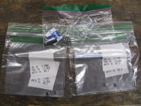
These are parts that are left from various projects, and perhaps others can use them. There are some discontinued and hard to get mosfets and bjts, numerous film caps for tube and ss amps, and a number of various electrolytic caps.
LARGE MOSFETS AND BJTS
TO-247 size
(2) IRFP 9140 n channel mosfet
(3) IRFP 150 n channel mosfet
TO-3P size:
(10) FQA 9P25 p channel mosfet
TO-220 size
(10) IXTP 08N100D2 N channel mosfet
(2) DN2535 N5-G n channel mosfet
(4) IRFP 510 n channel mosfet
(12) STF 3LN 80K5 n channel mosfet
(12) IRF 610 n channel mosfet
(6) IRF 9510 P channel mosfet
(6) D45H11 PNP bjt
SMALLER FORMAT FETS AND BJTs
SMD
(10) 2SK2145gr
(100) 2SK209gr
(8) BSH111 bkr
TO-92
(19) BSS 129
(2) DN2535N3-G
(4) J112
(2) BC546a
(8) BC63916
(6)BC 546bta
(2)KSC1845
(14)ZTX550
(9)BC640ta
(20)BC556bta
(6) KSA992 fbu
TO-126-3
(4)KSC2690 ays
(6)KSA1220a
SILMIC II CAPACITORS
(2) 1000uf 6.3v
(6) 1000uf 25v
(1) 1000uf 35v
(4) 10uf 50v
(4) 22uf 50v
(5) 47uf 25v
CERAMIC / MICA CAPACITIORS
Mica
(3) 5pf 500v
(6) 10pf 500v
(1) 100pf 500v
(4) 200pf 500v
(1) 220pf 500v
(4) 420pf 500v
(2) 500pf 500v
(3) 680pf 500v
Ceramic
(2) 390pf 1 kv
(2) 2000pf 6kv
(5) .1 uf 50v x7r
(10) 1uf 50v x7r
(2) 2.2uf 50v x7r
AXIAL ELECTROLYTICS (TUBE AMP)
(3) 25uf 50v Sprague Atom
(2) 22uf 500v F&T
(2) 22uf 400v Nichicon VX(M)
(2) 16uf 475v F&T
- 47uf 500v F&T
- 10uf 100v Nichicon VX(M)
RADIAL ELECTROLYTIC, TUBE AMP
(1) 250uf 500v JJ
(8) 100uf 450v Nichicon GU(M)
(2) 100uf 450v Nichicon KV9M) snapcap
(1) 47uf 450v Nichicon CY(M)
(1) 10uf 450v panasonic CEEB
(2) 10uf 200v Nichicon CS(M)
(1) 22uf 450v Panasonic CEEB
(1) 22uf 450v Nichicon CY(M)
(1) 56uf 450v Nichocon KX(M)
ELECTROLYTIC CAPS, SS AMP TYPE
(2) 47uf 10v Nichicon
(1) 100uf 10v Nichicon
(4) 220uf 10v Nichicon Muse Nonpolar
(6) 15,000uf 16v Nichicon VZ(M)
(4) 15,000uf 35v Nichicon GY(M) snapcap
(1) 1,000uf 35v Wurth
(4) 220uf 50v Nichicon Muse
(4) 10uf 50v Nichicon Muse Nonpolar
(2) 220uf 50v Nichicon
(3) 470uf 63v Panasonic CEEB
(4) 1000uf 63v Nichicon VR(M)
(2) 100uf 35v Nichicon VX(M)
FILM CAPS
CDE 940 Axial
(2) 10,000pf 3kV
(2) .22uf 600vdc
(4) .22uf 2kV
(1) 1uf 1kV
Radial, mostly panasonic type
(10) .1uf 630v
(2) .1uf 1000v
(4) .22uf 630v
(6) .22uf 100v
(4) .33uf 630v
(2) .68uf 250v
(2) 1 uf 100v
(2) 680pf 63v
(2) .47uf 63v
(8) 10,000pf 100v (zobel)
(8) .15uf 100v (zobel)
(2) 1 uf 520v
Wima Caps
(4) .01uf 100v
(4) .01uf 1 kV
(4) 1uf 63v
(3) .47uf 400v
(2) 1uf 400v
Guitar Amp type caps
(4) .1uf 600v 716P orange drop
(6) .1uf 630v Illinois axial caps


