• Poll Poll
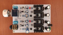
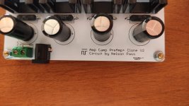
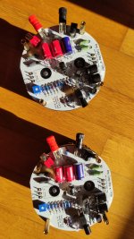
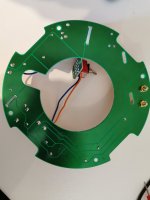
Firstwatt F3 clone PCB

F3 PCB mounting holes -Universal vs previous F2j pattern

  • Universal mounting specs from DIY audio store

    Votes: 4 66.7%
  • Mounting specs of my F2j PCB

    Votes: 2 33.3%

Hi,
Now I have the LU1014D,thinking of making a PCB for F3.
I already have F2J working and happy with it. Perhaps I will assemble one just to hear the difference.
Not decided on price etc but it will be done professionally by a PCB designer.
I am thinking seperate left and right Chanels with a power supply board in a set.
Please let me know your interests here so I can have an idea if it is financially viable plan.
Thanks
After may attempts it seems like some progress has made by the designer, hoping to finish it by last week of October 2018.

CAST: Compression Assisted Subwoofer Technology ?

I'm playing a lot with F.A.S.T. project for a while, and i was wondering about the ''C.A.S.T.'' alternative, where the Fullrange driver is replaced by a Compression driver...

In my case, that would be hornless, as discussed in that thread
http://www.diyaudio.com/forums/multi-way/300628-official-hornless-compression-driver-thread.html

But of course one can use a short horn as well.

In both cases i think the use of an DSP/EQ is mandatory; massive gain adjustements will be needed, steep xover slope, EQing, etc...
I didnt try it yet, but i think it might work good. Not quite sure about the upper end though, because the only CD that are going low enough (400-500hz) are most of the time the larger 4'' diaphragms, and they might not be at their best @ 10khz+ but still, i think we can get something pretty decent on 9 octaves, with extraordinary undistorted potential SPL output 😱

Also, the less expensive option (and maybe a better sounding one?) would be to use a 3'' diaphragm (2'' throat) along with a subwoofer that still in his comfort zone around 700-800hz, like the TIW250XS or the 8W1v3...

Food for thoughts! :deer:

Fisher 800C FM problems

Hi All

I am having issues with my 800C which seems to be in the FM limiter tube? V6(6AU6)
It is a new tube and has been swapped with others with same results.
I am getting more than double the stated voltage in schematic of (44V)
99Vdc at pin 6 (G2).
Plate voltage(pin 5) is 10v higher at 166 and pin 1 grid is a measly-.42V when it says it should be -3.4V
I have checked most resistors that have measured pretty close to stated value around FM section.
The FM brings in a strong signal at meter, works in FM stereo filter but FM Mono is weak and distorted audio.
AM doesn't work at all.
Any thoughts?

Considering a line array

Feeling it's time for a project and have been keen on building a line array for some time. Have read lots here and a few papers over the years.

What do people think of the following driver:
https://www.daytonaudio.com/product...-magnet-aluminum-cone-full-range-driver-8-ohm

Considering using 32 of them per stack, without the addition of tweeters. Would such an abundance of smallish drivers with seemingly OK high-end negate the requirement for addressing the high frequency?

For info, I can't hear a thing above 14 kHz, am 41 and plan on getting older where I'm expecting to largely appreciate wonderfully clear mids.

I do have some experience with miniDSP products, making measurements and tinkering with EQ.

If these drivers are not considered good, then curious to find another ~2.5" ish that would do the job. However, I like the idea of giving them a try but couldn't resist asking the community how daft my idea is first.

Lastly, don't let anyone in the Elsinore thread know I'm planning to build something to compete with them for movie night. My Elsinore's are great, but I want a new toy.

Which Tokin amps should I build?

I have 2 matched pairs of THF 51S and 2 “loosely” matched pairs of 2SK180, all ex Prasi. So I’m trying to decide which amps I should build with them. Some of you guys have built lots of these SIT amps so I’m wondering if you have any stand out favourites ?

And before you ask ZM, they will not be going to your disposal facility 🤣
  • Like
Reactions: Murdoc

Music Angel KT88 tube amp schmetic needed

I have a music angel tube amp model xd-se with kt88's. It is still under warrenty but emailing for the last week,I got no reply.I get hum on one channel only(seperate power supplys )so It looks like I will have to repair it myself.The hum stays the same no matter what the volume is so I'm thinking power supply(filter cap).Any ideas. swapped all tubes from other side and still hums(not a tube problem). I need a schmetic of mine to test further.Would a filter capacitor go so soon?The amp is about 2 months old with only about 10 to 20 hrs on it.

Soldering repair on JBL 2226 drivers

As part of a job lot of things I got 6 x JBL 2226 drivers for cheap, however I was disappointed when I got round to trying a few out that they didnt work, and more disappointed still when i then tested them all and only 1 didnt have an open circuit!

After much chin scratching and prodding, i cut the dome off one and saw that the thin flat wire that was exposed between coming out from its epoxy tunnel and into the voice coil had oxidised and crumbled to nothing. Badly stored I suppose, damp.

So, simple fix I thought, rather than a full recone, solder a bridge wire across the failed wires and epoxy over the bridge and hey presto.

Sadly, not to be! I cannot for the life of me get any solder to stick to the little flat wires. I have tried gently sanding/abrading/scraping any coating off, i have tried a couple of types of flux and bought a new soldering iron. Ive not buggered two of them by trying so much and the flat wires have come off at the VC, so i think they probably now are re-cone jobs.

However, the 4 remaining I have yet to fiddle with. Does anyone have any experience with this problem? Any ideas for how to get solder to stick to these $£$&$%ing wires?! Otherwise Ill have to sell them all as baskets which would be a shame for such a fixable (in theory) issue.

Woofer placement and non-symmetric offset.

Building a bookshelf speaker and need to hear your thoughts on placement of the driver on the front baffle.

I am using an 6” Tannoy dual concentric (coaxial) driver but for all purposes it is more similar to a full range driver than a traditional multiway with separate woofer and tweeter. So the question is;

“Basta edge” software is showing me that the driver has lowest ripple from diffraction when placed in the corner of the baffle. However I do not see any monitors being built with such driver placement. It is usually on center

why? Shouldn’t it always be in the corner as the software is modeling the flattest response?

Thanks for your input!

RV Audio Plans, Horns, OB, Omni, many ideas, all have issues with area, advice greatly welcome!

RVAudioPlans.jpg


RVAudioPlans2.jpg


Countless hours going over the layout changes in the RV as well as studying just about every speaker and sub design I can think of and keep coming up without a solid answer.

There will be build in book shelves on the back wall, ceiling mounted fold down TV, all audio gear located behind desk drawers except tube amp(if used) and maybe the DAC.

Two dedicated power circuits installed, dual shielded from PP to outlets, one just for sub amp(s).

Considered LX Mini, 521, H frame OB subs, as well as many other OB designs including Kantuck, Lii, etc..........

I have a couple ofl quality powered 15" subs and sealed ID 15's but want to build the subs into the back wall and have room for ported or sealed, would love to go with some high QTS drivers and OB but just not sure I could make the work in the space I have to deal with. I was using an Arc Audio Black 12 sealed until recently and it worked very well with some wall mounted KEF line array speakers but I want a real system and stereo subs(might end up mono but never ran stereo subs so want to give it a try, I have an Arc 1100.1 amp I could use instead of the class H or AB 120v amps I have) I will need to EQ the subs most likely though I prefer a totally analog system that will probably be in digital.

I own Edgarhorn Slimlines, fully upgraded and love them. Dr Edgar was my friend as well so really want to use them but they are quite large and rather close to the seating area, they like being out in the room more than I can afford to place them. I have a fully upgraded Baby Sophia 10 watt tube amp they pair with very well so want to use it as well, part of why looking into OB.

I also have various Seas drivers I really like as well but nothing for OB

I have considered just using the upper section of the Edgarhorn with the super tweeters installed in them and building sealed or ported midbass units so they can be much smaller.

I do not want box speakers, I like different things and built more than enough of them over the decades so just not interesting though will go that way if I must.

Any and all advice will be greatly appreciated, even if not nice at least good for a laugh🙂

Thanks,
Rick
(formally known as RAAMaudio)

Can anyone ID these horn flares...?

Bought a job lot of horns (3 pairs), asked the guy what the throat diameter was on the two I thought might work and his reply was 'i dont know what that is' so I took a punt... and lost! Needed 2" and the two larger sets are 1". D'oh.

Anyway will probably move them on now but would be nice to get a bit more info on them, if anyone recognises them or might have an idea what cabs they came out of... especially the CD drivers, though they are quite corroded. Thanks!

Plastic ones, 345mm x 195mm
IMG_7585.JPG


And then the pretty large fibreglass ones 250mm x 490mm:
IMG_7590.JPG


and the mystery CD driver with very worn label
IMG_7511.jpg


And for fun ill include the third little pair (265 x 105) which ive googled and seems they arent that special but might hang on to, be fun for some smaller cabs to go over some 10"s or something.... might hang on to them for such a thing, DJ monitors or some of those micro reggae rig style cabs
IMG_7592.JPG

Acoustic Elegance Speakers

Hi everyone

I would like to ask you about Acoustic Elegance speakers. I live in Poland, where there are neither no dealer of these drivers, nor hardly anyone heard them. That's why I decided to ask here - someone would probably be able to help.
AE Speakers claims that they produce the best woofers in the world (ok ;-) ) and that their drivers are characterized by the lowest distortions of all. However, comparing with other drivers, it seems to be not entirely true, because in the low tone range (<100Hz) the competition from the pro segment is usually better. You can check it here:
1) 12" - drivervault
2) 15" - drivervault
Not mentioning about, eg. Revelator, or Illuminator series from Scan Speak, whose are even better.
Can you tell me how do they handle compared to the best drivers from "audiophile" manufacturers, like Scan Speak, Accuton, Focal, etc? Are they really that good? Is it worth to try?

Best regards
Damian

Counterpoint SA20 Chassis

I recently lost one of the 4 banks of 3 MOSFETs (or so my service tech said). I will make the chassis available to someone who wants it or wants to salvage the remaining 9 supposedly good Mosfets. I would rather do this than take it to the dump. Its in Raleigh NC so pick up is better but I will ship it if you pay. I have the box but it weighs 55 pounds. Silver front.

Spud SE OTP headphone amp

With my first SS amp in the crapper after a transistor failure and the bugger being more unobtanium than fancy tubes, I cobbled up a simple headphone amp for high impedance loads 300Ω and up. Only parts I had on hand, nothing to be bought.

The spud idea came to be because of a parafeed preamp 5000:500 transformer I decided to use as input as voltage gain 1:3.1, with hot-ish source output and 1ohm output impedance. The near zero miller of a cathode follower 6AS7G will be inconsequential and volume knob sits at 2 o'clock.

The twist is in the biasing, a 40H 50mA choke with 550Ω DCR, which delivers 27.5V of bias when the tube has around 105V at the plate. The values were eyeballed from the curves, trial and error with PSUD gave the me the right combinations of psu components to get the desired voltage.

A tube rectifier would be nice but I stuck with a SiC bridge for now, choke input and split rails. DC heating just because I always had some random occasional hash noise with the 6080 family and I'd like to see if this fixes it. That and I had a 6.3V LDO board doing nothing.

1669587797377.png


As simple as it gets, the mains transformer is a sowter 150V, input choke is a finement 12H followed by a 32H 432Ω one. The high DCR is just to lower B+ to the desired amount, if I go for a low drop tube rectifier I'll have to use a different one.

It looks better in person.
20221127_190911.jpg


The output tube is on a socket saver just to protected the flimsy 3d printer mounts from heat. Output caps are meant to be topside for easy cap rolling,Jensen oils installed for now. The holidays will be filled with cap/tube rolling experiments. This thing should make a really good buffer for a VFET build.
20221127_211944.jpg


Can't hear the noise floor and the sound is very smooth and pleasing. The case is a DIY from other projects but the bottlehead badge has to stay in honor of the company who got me hooked on OTL amps.

Options for wireless (or wired digital) synchronized stereo?

I have a 4 way active speaker system. I would like to split the amps and processing into two identical racks, so that this will actually turn into two huge active speakers - and I would like to get rid of the line level link between them and turn it into wireless.

As it is now, there are two independent 4 way DSPs with identical settings fed from a line level analog source (mostly BT receiver, but I want to be able to use an LP player as well).

One of the options using existing components would be to use two Bluetooth TWS boards - are there any options to this?

The other would be to use Ethernet interconnected DSPs - like Symetrix, Qsys, etc. - I could hide the Ethernet cable into the wall and provide sockets on the wall next to the power sockets. I would not do this with a line level cable.

I have a NUC PC ready with Linux and Camilla DSP to be able to use FIR processing. It works fine with one multichannel USB soundcard. Is there a way to make a setup where the NUC would be the master DSP and then send the processed audio channels (8 or 10 in total) to two slave devices, each running its own soundcard over Ethernet in a synchronized manner? Or having one master as streamer only and then two identical PCs with identical CamillaDSP setups receiving synchronized data?
Or any other way that would distribute the 10 channels over Ethernet from the central source/DSP into two places.

All of this is a "nice to have". Worst case, I can do it the traditional way with a single central rack (behind one of the speakers) and run multicore speaker level signal in a single cable to each speaker from the rack. Basically, I would like to know if any of the above is possible or not.

Help replicating a crossover to smaller board

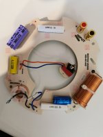
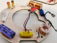
Hi, I have 4* 6,5" co-ax speakers that will be used in an atmos celing setup. The original crossover has a donut shape that is to big to fit in the cabinets so i need to copy the layout to a smaller form factor. I will might upgrade the components at the same time.
The original crossover have a "Boundary switch that can compensate for placement near a corner or wall, this feature do I not need.

I'm a newbie so do I do need help how to make a similar filter without the boundary switch, and wich components to buy (or use existing)

I'f anyone could make a skethc that I could use to wire and solder I would be extremely grateful.

Have attached pictures and a sketch attemting to trace the circuit board, but am not confident I got it right ..
Thank you.

IMG_20210325_135557.jpgIMG_20210325_142122.jpgIMG_20210325_135609.jpg
Sketch.jpg

Trying to understand how poles (vertical asymptotes) and zeros apply to an amplifier.

Searching in the hope I understand more about poles and zeros, I found the following document, but it is very terse, and there are no specific examples using amplifiers. The transfer function is used as a representative of an abstruct input/output system with no reference to a real amplifier.
Mathematically, it is easy to understand what poles and zeros are by studying the transfer function H. Zeros are solutions for the numerator and poles are solutions for the denominator.

Now the fun: according to the document, plotting all solutions for the transfer function on an Argant Diagram should give a clear idea as to how stable a system is. Poles in the (-, +) quadrant and the (-, -) cause a system to be unstable. Poles in the (+,+) quadrant and the (+,-) quadrant point to a stable system.

Why? There must be a logical reason. And, more importantly, how does the transfer function for a real amplifier look?

Mission 700 woofer refoam

Hello,

I was lucky to be given a pair of Mission 700 speakers. The foam surrounds have completely disintegrated and I'd like to refoam them but one of the cones is a bit bent/distorted - please see the photos. Is there anything I can do to straighten the cone or would the new foam straighten it up?

The Monacor SPH-210 is suggested as a replacement but is kind of pricey and I'm not sure it would work with the crossover so I'd like to stick with the originals if possible.

Any advice would be much appreciated!

Mission-700.jpg
woofer-1.jpg
woofer-2.jpg
woofer-3.jpg
woofer-4.jpg

2x12 Kick design

Hey,

what do you think of my kick bin design?

Here's my design principles:

Range:
-I'm aiming for 80-200Hz kick bin
Size:
-It's going to sit on top of a XOC's TH18 and I wanted a square front, hence these max dimensions
Driver:
-12NW76 is in budget and seemed like the sturdiest choice. 12ndl76 would have actually give a smoother response but I chose more Bl and Mms.
Response:
-It's not pretty, will the lumpy response affect sound even if I level it with EQ?
-It will be used mostly one per side, but using multiples would also level the response
-I wanted good efficiency in target range, which I think is somewhat achieved here (HR models peaks 50%, lowest 20%)

I would appreciate any feedback in why you think this will / will not work, or how you think it might sound?


kick 212 HR.jpg
  • Like
Reactions: seanny

SIT amp simmulation, 2SK79+2SK82 push-pull

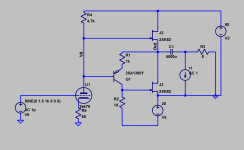
Hello all.
I am inspired by the L'amp by Michael Rothecher and other valuable information in DiyAudio community.

I simmulated a amplifier using;
2SK79 as a gain stage,
BJT as a phase inverter,
and Push Pull 2SK82 as a final stage.

SIT models are from Micheal's 2SK82 model and from Aumi's lab 2SK79.
This circuit topology have been used in my all tube 6FQ7 headphone amplifier for long time with good sound quality (smooth and natural, people say).

In this simm, the output power would be 14W max at 50v DC and 39W at 80Vdc . The Zo would be 1 ohm. 2SK82 Idle current is 0.8A-1A.
The THD is not good mainly because gain stage is simple single SIT.

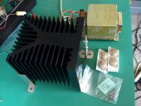
I gathered following stock parts to make this amp real;
big heat sink (120mmHx130mmWx150mmD),
2 pairs of 2SK82,
2SK79's,
trafo probably produce +/-40V DC,
and no 50VDC electrolitec capacitor on hand.

The power supply must be LR separated low ripple type, otherwise noise and crosstalk will occur.

I am hesitating to build this amp right now because of the power consumption. In Japan, after TEPCO Fukusima accident, No nuke is working and electricity charge have been rising . But I also think the sound may be very good. Is this a late comer?
How do you think?

Attachments

  • 2SK82 pushpull.png
    2SK82 pushpull.png
    17.8 KB · Views: 758
  • SIT amp.png
    SIT amp.png
    265.4 KB · Views: 744
  • P5173583.JPG
    P5173583.JPG
    216.7 KB · Views: 763

Line Arrays, directivity and impulse response

Hi Gang,

I'm afraid I'm about to ask a question that I may not be prepared for the technical responses to, so bear with me.

I have been thinking (but not tinkering) a lot with the idea of line arrays. In part from Tekton speakers, in part from reading Roger Rusell's page on column arrays:

My Experience with Column Systems

To restate Roger's point of view, the per-driver lobing and comb filtering is not an issue with the impulse response of a speaker, and that these effects are only audible with steady state signals.

If that is true, does that not also imply that the idea of controlled dispersion due to having an effectively very large vertical driver is fake? In other words, does the controlled directivity of an array only work during steady-state testing, but not for real music?

Gaaaaaaaah! My head now hurts.

Which Amp for 15 Ohm Lowther PM6As?

I read Nelson’s 2004 article on current source amps, but both the speakers and the amps have changed since then. What is the short list of First Watt amps for these speakers? I am open to commercial First Watt amps.

I am going to try an SLOB, still figuring out the bass unit, with a PAP. I have some 21” B&C drivers, but they might be a bit garish and have too much moving mass, for this project.

MBB relay design

I've been working on an audio project and I need to source some MBB (form d) relays. The thing is that these are quite hard to find nowadays.

After some online research I see that some people say that it's possible to use two BBM relays (with a cap in-between?) in order to create a MBB one but unfortunately I can't get my head around it.

Could someone explain in more detail whether this is possible and if so, how it's done?

What is the difference between horn and acoustic lens ?

Hi ! while horns are quite discussed i have found very little discussion about acoustic lenses
Anyone has experience with lenses ? i see that some Genelec speakers use them and i guess with great results
https://www.thebroadcastbridge.com/cache/uploads/content_images/Genelec_1235A_789_522_70_s.jpg
More in general what intrigues me is the idea of using conventional drivers (i.e. not compression ones) with lenses or even horns
If i am not wrong at Avantgarde they load with horns both cone mids and dome tweeters ?
https://6moons.com/audioreviews/duomega/strip5.jpg
Do you know of any commercially available horns or lenses that can be adapted to drivers of different diameters ? to make some experiments ?
A nice thing of these accessories is that they limit the H and V dispersion I like this a lot

Thermal Grease

G'day Guys,

Any recommendations as to thermal grease.

I have typically used Artic silver I had left over from building computers however I have seen it stated somewhere that this is not recomended for building amplifiers as it is conductive and could lead to a short.

https://nz.element14.com/multicomp-...ase-30g-white/dp/3267499?st=heatsink compound

This would be one of the cheapest alternatives available to me 'locally'.

Noise with BeoLab 8000 & Up2Stream Mini v3

I have been working on transforming a wired active HiFi speaker into a streaming wireless speaker.

Here's what I combined/my items:
  • WiFi audio streamer module: see link
  • 230v AC to 5v DC converter, the (original Apple iPhone charger type A1400: see link
  • An active speaker, so with built-in 140 Watts A/B Class amplifier.

How it's done & connected
This is what my build looks like. I integrated everything inside the speaker casing:
  • 230v AC > 5v DC converter - I used the official Apple iPhone USB charger as the AC/DC converter. It is small and easy to build into narrow spaces (and its ‘cleaner’ than a lot of step-down converters one buys online). The iPhone charger gets 230v AC from the incoming 230v AC power in the active speaker.
  • Up2Stream Mini - Powered by 5v DC coming from the Apple iPhone USB charger. For audio signal connected by a shielded audio cable: mini-jack on the Mini side, and connected to the audio in connector (RCA/Line-in) on the amplifier side.

See the drawing below.

Mini.png


Problem
Everything works perfectly, but one thing: Ripple!
'Ripple' as in a ratteling noise.


Question
Who can help with a solution?

Factors effecting group delay between different drivers

Does anyone know what factors (ts parameters), between different drivers, that directly effect group delay near the tuning / F3 point of an enclosure? I understand the major differences between enclosure types but how do; cone mass, motor strength, mechanical losses etc effect group delay?
Probably best to consider all of this in sealed cabinets for simplicity.
Thanks in advance.

QUAD 303 biasing diodes question / puzzle ??

Hi all.

Hope somebody can help.
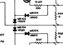
I have a Quad 303 which was faulty but i've fixed the fault ( open cct resistor ) and I intend to make 2 new amplifier boards and PSU board from scratch with HQ components throughout. Im puzzled by the schematic for the 303 and the actual board ? - The schematic shows 4 diodes around transistors tr103 and 104, but the actual amplifier has only 2 diodes ? I havent as yet verified why there are only 2 diodes fitted , but I will trace the tracks - any ideas what s going on with just the 2 diodes. Thanks . attached is a portion of the schematic im talking about. this has been posted in other sections of the forum, apologies if this offends ?

Attachments

  • quad 303.jpg
    quad 303.jpg
    19.7 KB · Views: 90

1/4 wave vs sealed

I recently built two subwoofers. The first is a 1/4 wave TL with Fs = 34 Hz, the second needed to be fairly small, so it's a sealed woofer with a lot of stuffing. These aren't expensive or anything, but here are my thoughts.

The 1/4 wave TL does create earth-shaking bass, but it's really not well-defined bass. The sealed sub also thunders, probably not quite as low or as efficiently, but the quality of the bass is so much better.

Interestingly, it's what I always thought of TL speakers - definitely excellent bass extension, but not crisp. My guess is this is why a low Qts is more suitable in a TL.

I will need to do some direct and extended comparisons next.
  • Like
Reactions: seanny

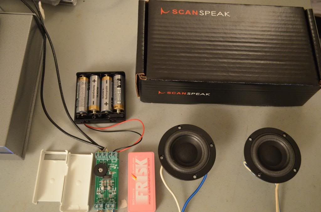
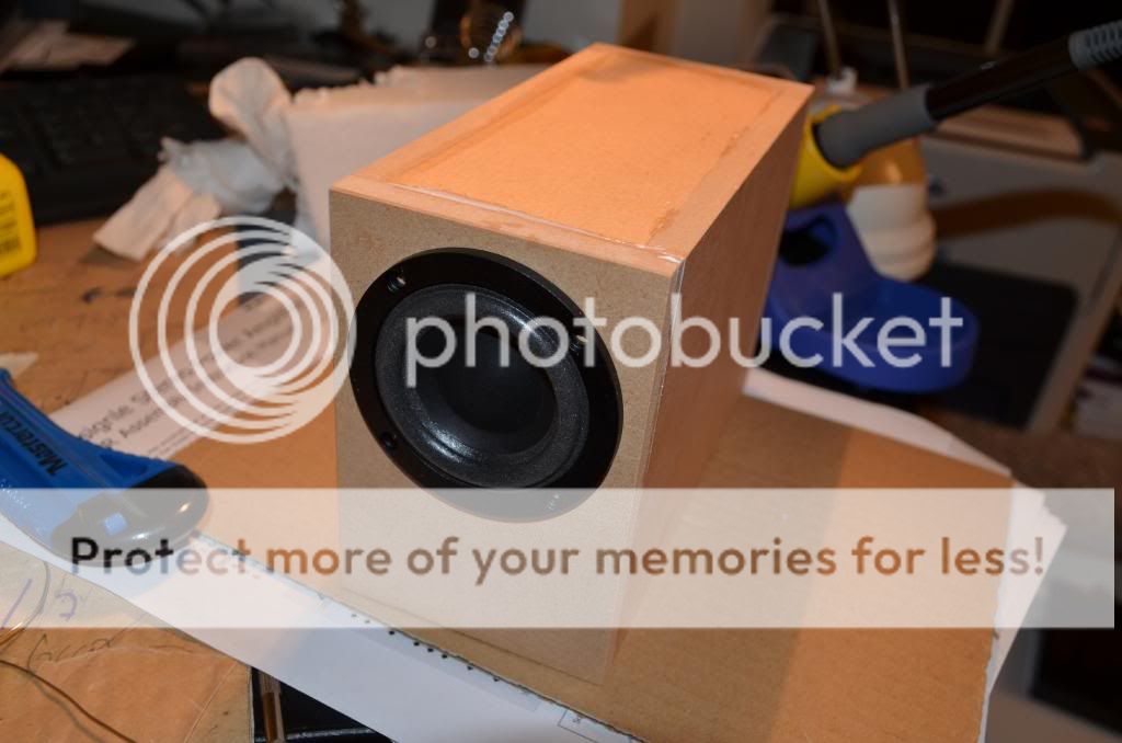
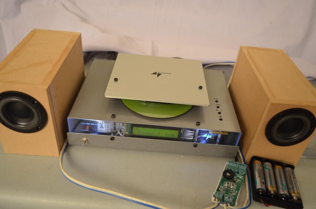
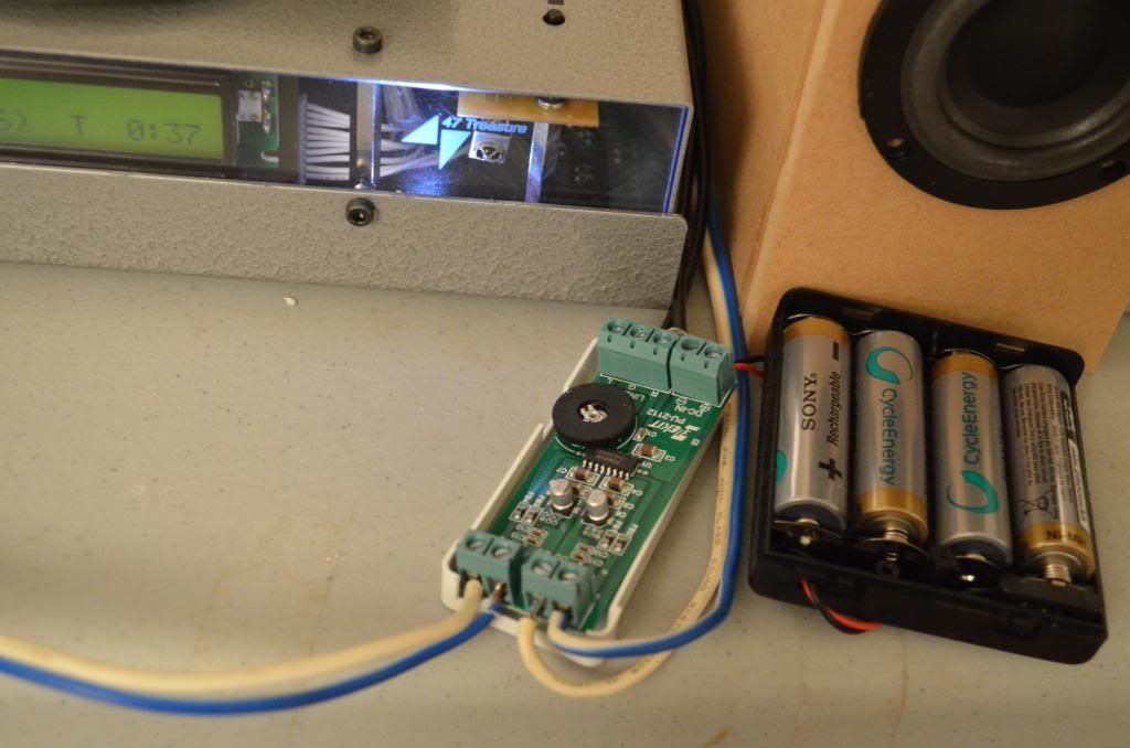
Elekit PU-2112 with Scanspeak 5F8422T01

DSC_0151_zpsb0bc7d0f.jpg


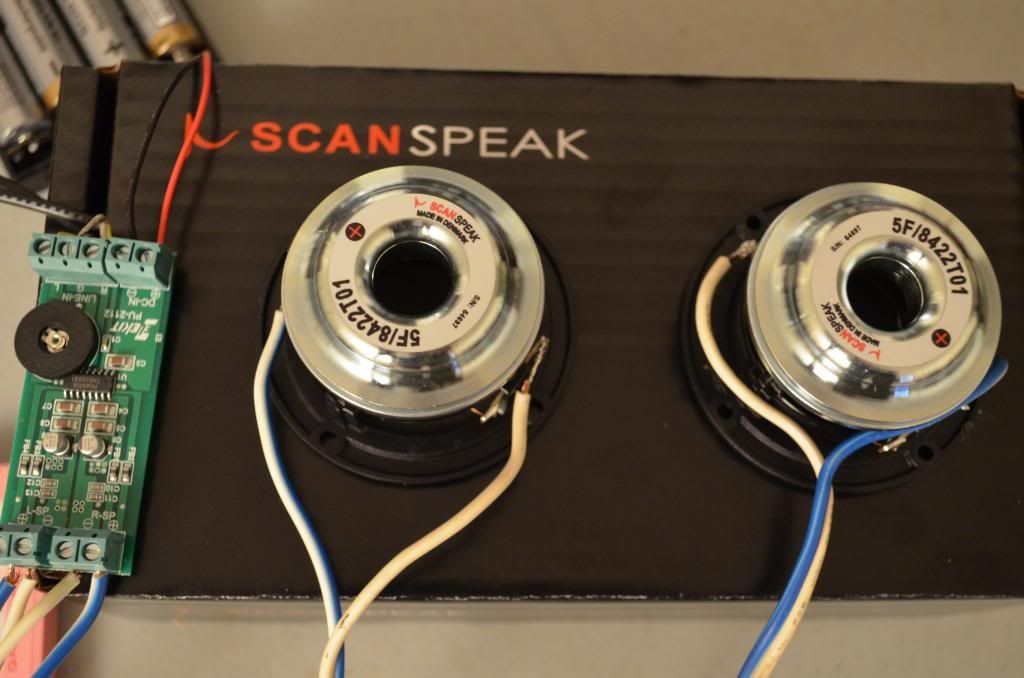
The 5F/8422T01 is the smallest ScanSpeak speaker component. Also 5F/8422T01 is the Rolls Royce of 5cm speaker driver. $56 per piece.
- 22 mm titanium voice coil,
- machined magnet parts,
- neodymium magnet,
-one-piece paper cone, foam surround.

5F/8422T01 is a good match for PU-2112 digital amp. Pretty good sound.

Elekit PU-2112 with Scanspeak 5F8422T01 2inches/5cm

This system will demo in 2014 Montreal Audio Show and 2014 AXPONA.


STR-DE545 Sony with right channel low output. Still present but very little sound.

Hello Forum,

I am hoping to get some advice on where to start looking for problems that I can fix on this old sony str-de545.
I have the schematics from the sony service manual. Symptoms are right channel sound is running at about 20-30 percent of the left channel in terms of volume. Other than that function is normal. I have also found R699 and R691 are running hot. Around 105C. They are found in section 3-8 Main 3/3 Grid B5. The other thing that is weird with this are the voltages. Im seeing the B+ and B- running 11 volts higher than they are called out in the schematic. So The 46.7 B+ from the schematic is running at around 58V and the 30 volt is running around 41vdc. B- is the same magnitude but negative. I am not a analog guru and not the best at determining the voltages though these transistor circuits in the schematics. The nice thing is that sony has voltages on the schematic which reduces the needed knowledge for some of that. Examination on the right channel amplifier around Q751, 752 753, 754 the voltages are about what the schematic shows. Plus minus a tenth of a volt. The main observation Im seeing so far the differs from the schematic are the B+ and B- voltages. Where they are running at listed +11v (-11) compared to the schematic. What I am finding weird is that on the main schematic 3/3 page if I look at the B+ and B- voltages coming off the bridge it looks like on that node 9.7v is the voltage as it goes into a few 7805 regulators. on the nedigive side it looks like -9.7 on the schematic. But in the circuit down stream I was measuring those higher voltages. Weird.

How do folks usually diagnose an issue like this? Maybe put a sign wave in on both left and right channels and see how it differs as you work though the circuits. Making sure the magnitude is equal as you go though the stages?

On the hot resistors I'm not exactly sure where I should be looking to determine what has failed. Those are found in section mainboard 3/3 at the top of the page. I have already touched up all of the soldering on the back.

I have experience with electronics, but not in analog amplifiers. Suggestions on where overall to start looking for issues would be helpful, or advice, like toss it and buy a new one. Ha.

Thank you
Matt

Help identifying a resistor for Mastering Labs crossover

Hello,
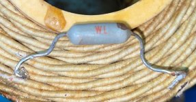
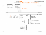
I have a resistor out of Mastering Labs crossover that measures 3.4R. The one in the other crossover measures 3.6R, but has no identifying marks. According to the schematic I have, it is 3.3R. I'm going to put Brown Devils in so thy all match. The issue I have is that my crossover is slightly different then the schematic. I have a 5 uF cap where the schematic is 5.5 uF and there is another 3.3R resistor stated where I have none. These crossovers haven't been monkeyed with until this monkey got them. Thanks for reading

Attachments

  • !cid_871bb565-0d96-4f37-af1b-d069485bcd10@namprd20_prod_outlook.jpg
    !cid_871bb565-0d96-4f37-af1b-d069485bcd10@namprd20_prod_outlook.jpg
    214.1 KB · Views: 199
  • !cid_27293b2c-6dae-48f7-bf94-45f943d9ebb7@namprd20_prod_outlook.jpg
    !cid_27293b2c-6dae-48f7-bf94-45f943d9ebb7@namprd20_prod_outlook.jpg
    168.8 KB · Views: 198
  • MasteringLabs2.png
    MasteringLabs2.png
    110 KB · Views: 237

Pipewire and wireplumber problems

I don't know if I should post here or on gitlab...

I'm trying to run "wpctl" to check status of wireplumber / pipewire and getting this error output

Code:
[pipewire@archdebug ~]$ wpctl status
C 15:35:41.164930            wp-core (null):(null):(null): wp_core_constructed: assertion 'self->pw_context' failed
Segmentation fault (core dumped)

I've tried as root - same. pipewire is a user in a custom pipewire plus root group.

I'm running pipewire and wireplumber on a Raspberry Pi 3B+ with ArchlinuxARM (latest distro / upgrades applied).

All user systemd services are running fine (pipewire.socket, pipewire, wireplumber). Processes are running as root

The pipewire process does have this error in the log (journald)

Code:
Dec 02 15:04:58 archdebug wireplumber[2564]: [32:04:53.067701151] [2564]  INFO Camera camera_manager.cpp:293 libcame>
[root@archdebug monitors]# systemctl --user status pipewire
● pipewire.service - PipeWire Multimedia Service
     Loaded: loaded (/usr/lib/systemd/user/pipewire.service; enabled; preset: enabled)
     Active: active (running) since Fri 2022-12-02 15:00:06 NZDT; 38min ago
TriggeredBy: ● pipewire.socket
   Main PID: 2517 (pipewire)
      Tasks: 2 (limit: 2292)
     Memory: 3.9M
        CPU: 385ms
     CGroup: /user.slice/user-0.slice/user@0.service/session.slice/pipewire.service
             └─2517 /usr/bin/pipewire

Dec 02 15:00:06 archdebug systemd[1990]: Started PipeWire Multimedia Service.
Dec 02 15:00:06 archdebug pipewire[2517]: pw.module: No module "libpipewire-module-x11-bell" was found

I am not running Xterm/11 and I had thought I'd commented that out.

I am running default .conf files (apart from the comment out above in an attempt to fix the error). installation was via pacman. Packages:

Code:
[root@archdebug ~]# pacman -Qi pipewire
Name            : pipewire
Version         : 1:0.3.60-3
Description     : Low-latency audio/video router and processor
Architecture    : armv7h
URL             : https://pipewire.org
Licenses        : MIT  LGPL
Groups          : None
Provides        : libpipewire-0.3.so=0-32
Depends On      : libcamera-base.so=0.0.1-32  libcamera.so=0.0.1-32  libdbus-1.so=3-32  libglib-2.0.so=0-32
                  libncursesw.so=6-32  libreadline.so=8-32  libsystemd.so=0-32  libudev.so=1-32
Optional Deps   : gst-plugin-pipewire: GStreamer plugin
                  pipewire-alsa: ALSA configuration [installed]
                  pipewire-audio: Audio support [installed]
                  pipewire-docs: Documentation
                  pipewire-jack: JACK support
                  pipewire-pulse: PulseAudio replacement
                  pipewire-session-manager: Session manager [installed]
                  pipewire-v4l2: V4L2 interceptor
                  pipewire-x11-bell: X11 bell
                  pipewire-zeroconf: Zeroconf support
                  realtime-privileges: realtime privileges with rt module
                  rtkit: realtime privileges with rtkit module
Required By     : pipewire-audio  wireplumber
Optional For    : None
Conflicts With  : None
Replaces        : None
Installed Size  : 4.52 MiB
Packager        : Arch Linux ARM Build System <builder+xu2@archlinuxarm.org>
Build Date      : Fri 18 Nov 2022 06:57:11 AM NZDT
Install Date    : Fri 02 Dec 2022 02:59:51 PM NZDT
Install Reason  : Explicitly installed
Install Script  : Yes
Validated By    : Signature

[pipewire@archdebug ~]$ pacman -Qi wireplumber
Name            : wireplumber
Version         : 0.4.12-1
Description     : Session / policy manager implementation for PipeWire
Architecture    : armv7h
URL             : https://pipewire.pages.freedesktop.org/wireplumber/
Licenses        : MIT
Groups          : None
Provides        : pipewire-session-manager  libwireplumber-0.4.so=0-32
Depends On      : pipewire>=0.3.52  lua  libpipewire-0.3.so=0-32  libsystemd.so=0-32  libglib-2.0.so=0-32
                  libgmodule-2.0.so=0-32  libgobject-2.0.so=0-32  libgio-2.0.so=0-32
Optional Deps   : wireplumber-docs: Documentation
Required By     : pipewire-alsa
Optional For    : pipewire
Conflicts With  : pipewire-media-session
Replaces        : None
Installed Size  : 1962.68 KiB
Packager        : Arch Linux ARM Build System <builder+xu3@archlinuxarm.org>
Build Date      : Sat 08 Oct 2022 03:38:38 PM NZDT
Install Date    : Wed 30 Nov 2022 03:15:42 PM NZDT
Install Reason  : Explicitly installed
Install Script  : Yes
Validated By    : Signature

Any help appreciated.

Digitech Studio 400

Hi guys.
Merry pre-christmas to y'all!

A friend of mine just came back from France with a Digitech Studio 400. It worked fine when he was in France, but when he unpacked it after a rough flight, the display shows nothing, only the backlight was on. I was thinking it could be the display contrast function, but then again, my friend is an experienced sound engineer, and I guess the unit was not powered up while on the plane.
Any thoughts what might have happened?

Thanks in advance.

Philips "cracked carbon" resistors, good/bad for tube circuits?

I have a few tube amps/preamps to restore this winter, Dynaco, Eico etc. and have several sheets of these Philips service pack resistors, they are physically large for the indicated power of 1/2W, they are more like 1-2W size. I looked around the web and couldn't find any data for "902" but I suspect that is the part number for the card of Rs, not the actual resistors.

Does anyone know what model resistors these are and are they suitable replacements for tube amps?

Any help is greatly appreciated.

Cheers

Philips resistor pack.jpg

Suggest a Design - 18 inch Stroker

Hi Folks,

I have a Planet Audio FU18 subwoofer, which I believe is a clone of the old Cerwin Vega Stroker. It's a dual voice coil sub with a double stacked magnets, which I am told is similar to JBL's differential drive system. It's a very heavy driver, and is about 250mm deep.
IMG_3769.jpg


Specs as measured by Dayton DATS are as follows

fs 39hz
re 4.14
Vas 142l
Qes 0.31
Qms 6.25
Le 1.13mH

Power handling is 1000w RMS with a 10mm xmax

Can someone suggest a good design for the sub, less than 400 litres (around 14 cu ft), that maximises efficiency between 40 and 120hz?

So far I have modelled the keystone sub, which looks good, but given plywood in my country is 2400mmx1200mm, I would need 3 sheets to build to the 26.5" design width. Another thought was to try it in a ROAR15 box (despite my recent negative experience with the ROAR12).

Please throw some ideas at me as to what design may suit this speaker.

I'm happy to tweak Hornresp and create an Autocad model from the Hornresp inputs, but don't really know what sort of alignment I should be starting with.

Thanks in advance!

Quest Qmotion L600a peak light!! stuck

Hey guys, I have a Quest Qmotion L600a system and I was curious if anyone knows this system?
When I run music into it the sub works and the right satellite works but the left side is a bit quieter
and the limit light is constant red even when you have no signal running to it and no speaker attached.
It would be a massive help to narrow it down to either the output board or the pre amp board.
I'm thinking the pre amp board???

Cheers


qmotionrel.jpg

Trying to find vintage sensor switch used in Meridian an Arcam CD players

Hi,

I am trying to repair a Meridian 200 CD Transport which has a broken sensor switch to detect when the tray has fully opened. The switch is the same as the one used in the Arcam Delta series of players, see photo below.

I would appreciate it if anyone recognises the switch and can provide any info on it.

Thanks

David

Arcam_Delta_70_sensor_switch.jpg

Hcca25001 help.

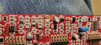
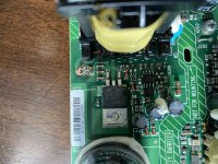
Hi guys. Getting ready to work on an Orion hcca25001 and the power supply card is missing a component on the power supply daughter board. The silk screen is messed up but it is q6-- something. Any help is appreciated pic is attached

Attachments

  • 16699355320136271150367289362881.jpg
    16699355320136271150367289362881.jpg
    472.4 KB · Views: 85
  • 16699355609802947529380312164968.jpg
    16699355609802947529380312164968.jpg
    403.9 KB · Views: 91

ICEPower 200ASC blown fuse on circuit board

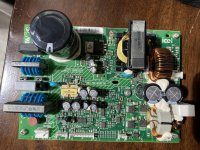
Hello everyone. New to this forum. I have a B&W ASW610 subwoofer. The 4amp replaceable fuse blew and I tried another fuse ( same spec) and it blew again. I decided to open it up and found that an internal fuse on the ICEpower 200ASC board had blown. My concern is this, I don’t know the value or the type of fuse I need to buy, as well what caused this fuse to blow. I do not see any other visible damage on the board. Thanks is advance I have posted pics.

Attachments

  • BEE794A7-F75D-4363-B087-23F56F4D8177.jpg
    BEE794A7-F75D-4363-B087-23F56F4D8177.jpg
    1 MB · Views: 577
  • F6578FC9-66A8-40A5-ADF2-20B74E172ED0.jpg
    F6578FC9-66A8-40A5-ADF2-20B74E172ED0.jpg
    1,006.3 KB · Views: 410

An Under-Appreciated Cabinet Material

Hello, All:

Here's a photo of a two-way design of mine with a ribbon tweeter. The front panel is made from an engineered composite, Richlite Stratum with a birch plywood core.

Richlite was developed during WWII for parachute "drop boxes" to airdrop weapons to partisans behind Nazi lines in Europe.

Today, Gibson Guitars uses Richlite for most of its fretboards; you can find precut fretboard blanks on Richlite's website https://www.richlite.com/

Richlite is so tough that it is certified as Kosher for food-cutting boards.

The faces of the panel are 1/8ths inch phenolic-resin impregnated paper. It takes a very nice finish, such as Osmo Polyx-Oil. The only caveat is that it is so tough, that it is tough on tools such as router bits.

Richlite sells "Partial Sheets" of all its products in 12 x 12 and 24 x 24 inch sizes. IIRC, the 12 x 12 sample for this project was $40 plus shipping.

NB1: That cabinet is my design, but the execution was by Corwin Butterworth, who was trained at the Rhode Island School of Design.

NB2: My relationship to Richlite is one of respect. I pay retail for my boards.

ciao,

john marks

Attachments

  • J Marks Eton Fountek Build.JPG
    J Marks Eton Fountek Build.JPG
    538.2 KB · Views: 618

What port diameter to choose

Hi,

I am planning on building a subwoofer box for my home theater with a digital designs dd506d2
The design will be a double reflex chamber tuned between 20-25hz with one chamber around 5 liters of volume and the other one around 20.

I have a question about what my port diameter should be:
I was thinking about 65mm the port will be 1 meter long this way (which is fine) and the air velocity at 100 watts will hit the 17m/s mark

A the moment i have a 8 inch infinity subwoofer with a port thats 50mm in diameter. This subwoofer has noticeable port noice/chuffing. So I dont know if a 65mm port will be big enough in diameter (the surface area of this 65mm port is almost double of the 50mm port)

Any comments would be highly appreciated

Modded RPi4 Board for better SQ?

Hello since i readed much about audio lately i wondered if it would make "sense" to mod a RPi4 board for "ultimate SQ" (kinda like the allo usb signature)

things i came across so far that do "in theory" make sense:

1. replace the DC/DC Converters, one step further would be to provide the different voltages directly but i think thats a step too far, and someone also posting here said good dc/dc converter do make nearly the same effect (maybe add filter capacitors too?)

2. filter capacitors for usb, maybe as a sort of decoupling for all usb devices drawing power?

3. remove the BT/WIFI modul or disable it in some way, since even if disabled in config it still actively transmits

4. replace the clock(s) for better ones

5. remove the headphone amp circuitry and maybe other unneeded stuff?

any other ideas/suggestions?

Tim Curtis pointed out in the moode forum (where i posted this thread too) that it may be a good idea to use the CM4 + I/O board, this would make it possible to buy the cm4 without wlan/bt to begin with and has emmc on board if wanted (and in the end it costs pretty much the same as a normal rpi4b+)

i wanna focus on usb playback and the i/o board seems to have a good layout, the pcie x1 could be used for a usb 3.0 board to drive a ssd and things like wlan/bt dongle (so the usb 2.0 can be used standalone for the dac, its also a good thing i think that the usb 2.0 chip is very close to the ports)
tho im not sure about the hat performace with this kind of board (official i/o board) since it has rather long lanes/traces

i also watched around for other boards (there are quite a few) but couldnt find any that looks better than the official one, most have just too much unnessacary stuff or too few usb ports... i specially checked those ones -> https://pipci.jeffgeerling.com/boards_cm (thanks for that jeff btw 🙂)

any ideas/tips are very welcome 🙂

Amplifer first few watt run at class A than class AB

While I was getting idea to use my 8 matched EL84 to a build a monoblock,
https://diyaudioprojects.com/Tubes/EL84-Mini-Block-Amps/
or something like a manely stringray clone

I was wondering how does commerical amplifer desgin their amplifer running the first few(8) Watt run at class A and run at class AB afterwards.
Is there any diy project or scheamtic I can refernce it to ? I am thinking to have the 4 nos of EL84 in push pull parallel runinng at class A in first 8 watts and run at class AB afterwards (maxium to 35W ?).

First Full Range Build... Any Last Minute Insight?

Hi all,

I've been wanting to try a full range tower speaker for a while. I'm used to building big cabinets and simple designs. But I've never had a full range speaker to work with. Figured I would start with that. I went through a few of the threads and one of the builds I saw struck my fancy, so figured I would start with something already known to work well and looks nice and uses affordable parts and isn't too complicated to build. I forget who's plan it was, but thank you to that person for sharing it, I shall try it I think!

Any last minute thoughts?

I picked up two Visaton BG20-8's for cheap and figured I'd start with this (I have these now).

Here's the plan I found in the other threads that was shared that I liked (thank you to the person that shared this, sorry I couldn't find a name I had saved this from a while ago, but want to be clear that I'm borrowing someone else's design here).

Is the voigt pipe more of a tapped horn or a type of transmission line? I'm confused with all the different types there are it seems.

I can't tell from the diagram, but is that 3/4th inch thick material or thinner? I'd like to use thicker 3/4th inch unless its not advised?

DDVP-20-01.jpg


Ultimately I will do a 2nd build, but it will be entirely from scratch using a smaller full range driver and a larger woofer for a WAF/FAST that I got interested in. However, I've yet to build crossovers yet, so again I wanted to start somewhere with full range without getting into that. I really like the idea of the simplicity of a single full range driver and a tower cabinet. So my first build will probably be the above drive and cabinet. It's not too complex for me to build and I like how it looks.

Goal for these full range towers will be classic 70's rock mostly.

Very best,
  • Like
Reactions: hmj

Help with impedance/TSP measurement in REW

I'm trying to measure TS parameters of drivers by myself.
I'm using these videos as guides:
Login to view embedded media Login to view embedded media
I have made the testing cable like instructed, checked it several times, resoldered the mic end a couple of times.
I have made successful measurements earlier with it, but now it just doesn't want to work anymore.
I usually had to restart my PC or switch sound cards (Realtek on Gigabyte x570 mobo or Asus Xonar d2x) to fix the problem and eventually I'd get it fixed, but not anymore.

I always get some type of this message with short circuit cal.
1643981881492.png


I have tried switching the channels, changing input and output volume in REW, changing bitrates (which somehow has also been a problem sometimes), switching sound cards, restarting, etc.
I had problems getting the open circuit calibration to work, but after a restart it seemed to work. Now I'm stuck on short circuit calibration, as I have been many times earlier and just given up...

Please help.
  • Like
Reactions: androxylo

Help me put these tubes into good use... I need a project

Hy,
I had recently acquired some parts from and old enthusiast...
Among the parts I got there are some tubes, most look new, unused in original packaging. Also there some retro looking pot knobs and such...

I would like to build something with them, search had revealed that those are mostly TV tubes, but also that they can be used for radio, preamp, amp,...

First of all I am aware that isolation transformer is a must, I had learned that the hard way, when I fryed all the ground traces on my pc motherboard.

TUBE LIST:
PL504
PCF801
PCF802
ECH84
PCL805
PCL86
PCC88

There is 1 piece of each, sadly no pairs...

And there was one that would need to be identified. It was in PCL84 box, but its writen ECH and B3B4 on it... filament needs 15v to glow and filament pins are 4 and 5.

So far I had just tryed filaments, all tubes have nice orange glow.

I already have EL84 amplifier that I had build few years back. It could use some preamplification, so I tought I could swap EL84 for PCL86.
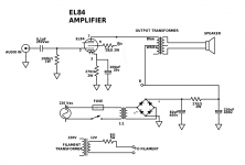
This is the schematic:
EL84-AMP-2trafo.png
What would need to be done except of rising filament voltage to use PCL86 and benefit some gain?

Deciding if I will modify this amp would be the first step so we can know if I will continue either with EL84 or PCL86 into the new project...

For new project I was thinking either preamplifier (I wont need it if I modify my amp), Fm radio if possible? Or even better some sort of ham radio... I always wanted tube ham radio and I possible I would build that.

I'm open to suggestions,
Thank you
  • Like
Reactions: TonyTecson

Audio Technica AT ART7/ART9 MC Cartridges

Title self explanatory..
Anyone have any experience with either of these cartridges?

I am contemplating buying one for one of my Souther arms. Given my ability to make arm wands with the appropriate mass if necessary either could be a good match.

I am currently running a Windfeld on one and a Royal N on the other as a point of reference. Also have run an Ebony H which worked very well, but is a bit laid back for my taste and doesn't have the bass capability of either of the aforementioned cartridges.

Mark Levinson 38S - mains voltage jumpers

Hi All,

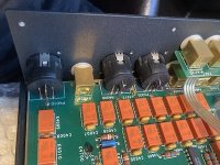
got ML38S with Japanese voltage. I know it is switched by jumpers (apart from frequency detector). Apparently located underneath PCB, but it seems it is not possible to remove PCB without cutting XLR connectors, which are Switchcraft brand. I made full restoration of ML 27, ML23.5 but never had any 3x series on my bench. Is there any access to jumpers other then fully removing PCB, or if not - whether its possible to remove PB without cutting XLRs?


IMG_7939.JPGIMG_7940.JPG

Expired / Discontinued & fake popular chips for chipamps - summary list [ongoing]

Hi! Thought i'd share my notes as I go through available reliable chips for chipamps.

I'm looking into making several amplifiers from popular designs, adapted to current realities. Many popular chips are discontinued and suffer from fakes, so I wanted to summarize my experience and search as I go through the state of affairs in 2022 (almost 23). This list is being updated. My current interest is in application to class A or AB, class D is excluded from this list. My next project targets a headphone amplifier or follower, but this list is not primarliy targeted nor limited to headphones.

Although an engineer (software), I have no experience in circuits outside of small projects, and am very grateful for feedback from those more knowledgeable. My personal goals are broadly guided by a desire for small amount of parts, possibility for reusing / recycling and best bang for the buck. The core principles behind my approach rest on the scientific method, so I aim to base my statements on replicable objective research and/or authoritative sources such as manufacturer information.

TDA 2030 / TDA2030 . 14 W hi-fi audio amplifier. Obsolete, according to ST as well as all suppliers for original manufacturer.

Discontinued by original manufacturer. Multiple fakes on Asian online marketplaces. Several published articles, including discussion on this forum, about marks of recycled chips (clipped & resoldered legs/leads), remarkings, etc. A somewhat reputable Taiwanese manufacturer is UTC, such as sold by Reichelt / Germany. I do have my suspicions about how exactly reputable UTC is, because their website UniSonic Technologies/UTC, when checked on Dec 1 2022, has an active bottom signature copyright date of 2011 and no HTTPS certificate, which does make me wonder if any care is given to the reputation of the company.

Alternative:
Possible replacement, with caveats and multiple opinions, is the NTE1380. Careful analysis of the specs for the specific replacement chip is warranted, as voltages as well as pin-outs may vary.

I would presume that someone getting the cheap kits or 10 for $3 chip bundles should be ready for the standard precautions and monetary and time expenses (referred further to as SP&E) before they use the Asian-sourced chips, with estimated expenses in the $30(50) to $100 range:
  • Getting a reliable multimeter for testing,
  • Making a test rig for the IC
  • Getting an electronic component tester
  • Insuring a DC protection circuit is used to protect speakers / headphones
  • Getting at least 10 IC components and thoroughly testing them, including overload, to make sure at least some resemblance of adherence to spec is maintained.

LM3875 - Discontinued

Fakes abound. Same SP&E. Replaced by LM3886, that has two additional signals, mute function and a virtual ground pin, that have to be dealt with if substituting. Some would say penultimately popular gainclone chip?


Active as of Dec 1 2022
  • LM3886 ( Texas Instruments (TI) ). 1 Ch, 20-94V supply stereo Class-AB amplifier. Highly regarded by many in the diy community.
  • LM317 and varieties (TI).
  • LM383T (TI) 7W Audio Power Amplifier 5-to-20V (TI)
  • LM1875 (TI) 20-W Audio Power Amplifier.
  • TDA7297 (ST). 15 W + 15 W dual bridge amplifier, designed for TV and Portable Radio applications. Highly regarded by many in the diy community.
  • TDA7294 (ST) monolithic integrated circuit in Multiwatt15 package, intended for use as audio class AB amplifier in Hi-Fi field applications (Home Stereo, self powered loudspeakers, Topclass TV).


To be continued
Quick question, to confirm my reading of the rules- is posting links to manufacturer and spec sheets allowed?

New VRX928LA and XTI6002 sound upgrade for church

Hello All,

My church is currently upgrading their very old PA system to JBL vrx928la arrays. They will be flown, with 3 units on each L&R and Martin xp118 subs onstage. The 3 vrx928 will be powered by a Xti6002. I'm learning this as I go and am unsure about how to hook up the 3 vrx to the xti in bridge mode. Plus this is the first time for me working with Neutrik NL4. Any help you can provide will be greatly appreciated. I don't want to blow some $1600+ speakers. I want to be sure I hook them up correctly. This will be easy for a pro, but our congregation doesn't have such a person and they want to avoid hiring one if they can help it.

TIA,
Dan

The best Audio Books and Magazines about Loudspeaker (like Speakerbuilder) - Overview

about the German Forum
Theorien und Literatur über Lautsprecher - Verstärker, Lautsprecher, Zubehör - Analog-Forum
you will find a good overview.
here on diyaudio I have found only this:
DIY Loudspeaker Books - diyAudio
loudspeaker books - diyAudio
about
www.hornlautsprecher.de - solutions in sound
a lot of datasheets and the complete book (in German) "Dichtung und Wahrheit" you will find as PDF file

Magazines:
Voicecoil:
audioXpress | audioXpress Magazine. Advancing the Evolution of Audio Technology - Since 1970 - test example:
http://www.moreleurope.com/data/mediablocks/ST 728 Voicecoil reprint.pdf

More books and magazines (also from other countries) wanted - thank you for additional advices.

post #15 under
https://www.diyaudio.com/forums/everything-else/196492-recommended-books-2.html#post6749607
shows a very interesting book concerning horn constructions

Nakamichi PA7 - Issue

Hi everyone,

Thanks for reading - I hope this is the right spot to post this.

I have a Nakamichi PA7 and the power just flickered on and off a few times - and now it won’t turn on. It’s plugged into a surge bar.

I was wondering if anyone could shine some light on what could have happened to it, I would like to try and repair it myself if it’s doable.

Appreciate any input, hope you’re all having a good day.

Thanks

For Sale Audio Precision Sys-2322

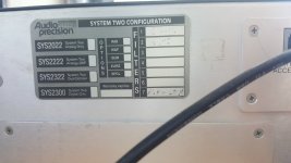
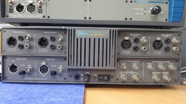
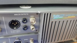
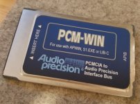
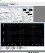
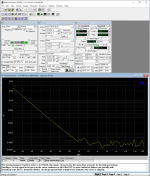
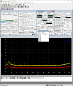
For sale an Audio Precision SYS-2322 with additional USB interface. The unit can be used with Windows 10 and 11 in a Desktop or with a laptop and the PCM card (I was using it with Bootcamp in an iMac without any issues). The unit works perfectly and passes all the tests, it only has a small dent on the front which was there when I bought the unit. It has been used in a clean laboratory (not in production lines or the likes) and it is well taken care of.

The bundle includes:
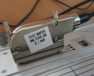
  • SYS-2322 unit with CCIR2k, CC468-3, A-Weighting and 20kHz filters
  • APIB USB adaptor, www.s1usb.com (worth 290$ + shipping)
  • APIB PCM card with cable (cable not in the pictures)

The unit is in Hong Kong, asking for 3,800USD including shipping to anywhere in the world or a reasonable offer.

Thank you

Attachments

  • 20200617_113629.jpg
    20200617_113629.jpg
    310.3 KB · Views: 130
  • 20200909_145058.jpg
    20200909_145058.jpg
    427.4 KB · Views: 125
  • 20200909_145103.jpg
    20200909_145103.jpg
    317.7 KB · Views: 128
  • 20200909_145119.jpg
    20200909_145119.jpg
    242 KB · Views: 136
  • 20200909_145138.jpg
    20200909_145138.jpg
    288.9 KB · Views: 126
  • 20201222_195307.jpg
    20201222_195307.jpg
    138.4 KB · Views: 133
  • AP 2.png
    AP 2.png
    402.9 KB · Views: 125
  • AP 3.png
    AP 3.png
    384.8 KB · Views: 121
  • AP Screenshot.png
    AP Screenshot.png
    468.1 KB · Views: 130
Projects by fanatics, for fanatics
Get answers and advice for everyone wanting to learn the art of audio.
Join the Community
507,520
Members
7,875,272
Messages

Filter

Forum Statistics

Threads
405,638
Messages
7,875,272
Members
507,520
Latest member
jbaudrion