FS: tubes, pcb and components for Pete Millett's DCPP Amplifier

I have those for years, realize will not be able to finish it, so it's your chance to have it, for less.

include:

PCB (the big red one), 4 big sockets
10 6HJ5, 6 6GU5
resistors and caps to stuff the pcb (can't guarantee all of them, but >95% at least)

I know the 6HJ5 is getting quite expensive now, so how about US$300 for all the things above? Shipping exclude.

Magnavox CDB473 CDM-2 mechanical clacking noise

Hi All:

The CDM-2 mechanism in my Magnavox CDB473 has started making a single acoustic CLACK noise when the PLAY button is pressed after inserting a disc. The noise doesn't seem to affect the unit's operation however, and I am able to easily set the laser power and focus offset adjustments as documented in the Service Manual. The noise is due to the pickup swing arm hitting its end of travel as it moves toward the center of the CD. The pickup has what looks like a small grey bumper next to the lens that seems intended to cushion the end of travel, but it doesn't seem to be doing its job. It is possible this bumper has broken and is missing the piece that would do the stopping, but I haven't been able to find any photos of this detail online. Does anyone have any insight into what the CDM-2 inner end stop bumper is supposed to look like?

Incidentally, I'm only using the player as a transport to deliver S/PDIF to a Museatex (Ed Meitner = EMM Labs) Bidat DAC.

Thanks!
DC

Thick Film Hybrid (not monolithic) Integrated Circuit Amplifier - Overview

Sanyo's STK series knows everyone - there were and are still a number of other types and brands, that are not as well known:

1) BC SVI3505A (BC Power Module - no exact informations)

2) Kenwood TA2030/TA2031
Eugen Gurskij Elektronik - ICs
Kenwood TA100WA
Audioklinik: Die Meisterwerkstatt für HiFi Klassiker ob Transistor oder Röhre in Düsseldorf.
Kenwood Hybridendstufen - und es gibt sie doch

3) Matsushita/Panasonic STK8040 (Technics new class A)
http://i14.ebayimg.com/01/i/07/4d/58/db_2.JPG
http://www.maxdat.eu/_data/Random/STK8040.jpg
audio-technics.fm.interia.pl/technika/amptech.htm
Amp model - hybrid model
Matsushita/Panasonic "RSN 36S5 A" "RSN 36S5 B" (Technics)
eBay Österreich: RSN36S5B RSN36S5 B Amplifier IC NEU (Artikel 130368471680 endet 19.06.10 13:13:41 MESZ)
data sheet information for RSN36S5A from www.ecadata.de

Attachments

  • Kenwood TA2030-2040JPG.JPG
    Kenwood TA2030-2040JPG.JPG
    12 KB · Views: 2,012
  • Kenwood TA2031.jpg
    Kenwood TA2031.jpg
    143.5 KB · Views: 2,071
  • kenwood_ta-100wa open.jpg
    kenwood_ta-100wa open.jpg
    136.9 KB · Views: 2,086
  • Kenwood TA100-200 W-WA six pack.jpg
    Kenwood TA100-200 W-WA six pack.jpg
    887.5 KB · Views: 2,244
  • Kenwood TA100WA.jpg
    Kenwood TA100WA.jpg
    104.5 KB · Views: 1,904
  • Sanyo STK850 Technics newClassA.jpg
    Sanyo STK850 Technics newClassA.jpg
    6 KB · Views: 747
  • Technics Hybrid RSN36S5B.jpg
    Technics Hybrid RSN36S5B.jpg
    131.8 KB · Views: 655

GB: Round #9; Fo-Felix AC Filter

We're on round #9!!!

5x20mm fuse option added for Euro buyers

Prices have increase some, but luckily it's minor


So over the years people have asked about the old version, made by someone else.

It's probably time for an updated one. This one is a bit different. You may notice it does not have following capacitors after the choke. I have tried both ways, and my preference is strongly without the following X2 capacitors. Also the capacitors prior to the choke are not varied in size because overall capacitance is more important - and they won't randomly resonate with each other.

The other major change is the addition of bypass resistors for the chokes. These don't ruin the filtration, but they do a good job of quieting the chokes that can get excited by different combinations of things on the mains.

fo9unnamed.jpg


Gen1 w/comoco's
IMG_1974_1_22.jpg


Here's how it is different in settling time from the original.
Fo_felix_vs_felix.png


Here's a comparison between resonances.
Fo_felix_vs_felix_resonance.png


*2oz copper PCB (1oz is standard)
*Weco 983ZD terminals, copper alloy and can accept 2 wires for daisy chain. These are also safer, particularly if you use solid core wire that otherwise likes to make cold solder joints you can't see.
*X2 rated capacitors for safety, 4x 0.47uf. They are alternated for CFC (capacitor field cancellation).
*Discharge resistor for X2 capacitors
Coilcraft Comoco choke w/fuse or Bourns 8120/8121-RC choke w/o fuse & 15/16A/20A() max sockets
*Fuse clips are beryllium copper 3AG & 5x20mm options
*120/230v operation (parts & pcb)
*Mounting holes are sized to work nicely with M3 screws and standoff kits
*Size: 2.25x4.25in

The Weco 983ZD are preferred terminals, but not always available as individual sale. For this reason I'm going to include them in the price of PCB, so that I can meet min order requirements for them and save everyone the shipping.

Price: $14ea ($10 per filter board, $2 per Weco, 2 needed per board)

Shipping: $11 US, priority USPS box
$20 CAD
$22 General international padded envelope (prices may vary due to a crazy world)

If ordering over 4x boards there may be an additional $10, depending on destination.

Need 32 filter board commitments to order.

#10

danbmellow 10​

B&C DE250 on Dayton H812

Was looking at some horns allowing a low ~800 Hz crossover for the DE250.
Came over this French site which shows fantastic extension and linearity with the Dayton H812 horn:

Grand Comparatif de Compressions 1 pouce - JustDIYIt !

FR-DE250.jpg


But Ampslab (Michael Chua's) measurements of the same combo doesn't give the same picture at all... Even if you look past the smoothing differences.

https://ampslab.com/blog/2020/06/12/dayton-h812/

H812_B3.gif


The measurements of the D220TI matches up pretty good tho :scratch2:

Any experiences with this horn out there?

Alpair 12pw Fullrange?

Hi Guys
Just wondering if anyone has tried the Alpair 12pw on its own. I can see it is discribed as a Mid woofer but the treble seems to roll off fairly gently.
Also I have a pair of A6P which I found to be too lifted in the upper regions for my taste, can anyone compare these to the regular fullrange A12p in terms of smoothness and character.
Thanks Simon

Classic monitor designs?

Hi.

Post here if you have constructed or found designs on internet about classic monitor designs.

Here is couple of what I have found.

http://www.troelsgravesen.dk/3WClassic.htm

http://www.troelsgravesen.dk/CSM_KIT3.htm

I don't seek for slim floorstanders or small monitors but bit larger monitors which have bass grunt by their bigger cabinet volume and wider baffle. And yes, they can be bigger than those examples. 8-12" bass would be fine 🙂

If you have seen cabinet construction with thin walled enclosures, please post here. I think some british speakers are made of thin material and they sound lively.

GE 8136 OTL tube headphone amp idea

Hello,

Was looking through my assorted tubes and found a handfull of GE 8136 Beam Tetrodes that i would like to build an OTL headphone amp with.

Not sure if anyone has actiually used this tube for an audio amp before but looking through the datasheet they seem to me at least like they could work.

First things first, i am not looking to make something necessarily objectivly good.

This is just to have some fun by designing an amp of my own with something thats not been done to death already like the 12A-whatever/ECC tubes. They make for great amps but thats not what this project is about 😛

The goals with this are:

  • To be able to drive my 50 Ohm headphones
  • Having a good time designing and building
  • Learning about general tube amp design
  • Learning about the specific design conciderations for Beam Tetrodes
  • Designing and building a clean PSU that can be used in this and later projects

I'm fairly new to designing amps, especially tube ones(Done a small amount of solid state stuff as cource work) so i expect this to need a lot of work. I havent gotten much further than looking at the datasheet and speculating but i threw together a sketch of what i am thinking so far.

I have no idea what to do with the screen with an OTL tetrode so for now in the sketch its just voltage divided to sit at ~125V plucked from the datasheets typical operation.

Other than that i am thinking of a V+ = 200V-300V and Grid Bias = -1.5V as these regions seem fairly linear with regards to the expected input amplitudes( <50mVrms / <0.14Vpp ).

Looking this over one last time before posting i realise that this might have a "huge" voltage output(~70V) and that Ra should be shrunk to something much smaller but i am not entirely sure, its late here so please enlighten me on this matter... 🙂

I have attached a sketch of the topology that came to mind first but it is probably going to need quite a bit of work. Happy to hear your thoughts on it as long as its not "wow this is dumb" or "why would you build this" but do feel free to point out any flaws in a constructive way!

Attachments

  • 8136_tubes.jpg
    8136_tubes.jpg
    211.9 KB · Views: 245
  • OTL_8136_v0.82.jpg
    OTL_8136_v0.82.jpg
    236.9 KB · Views: 261

Esoteric D02 Does not work usb

Hi! Help with troubleshooting the usb receiver on the esoteric d-02 DAC. The problem is that it is not detected by the computer. The drivers don't help. Windows writes that an unknown device. Everything works on another DAC of the same type. I called the whole board, all of it. I checked all the voltages and found different voltages at two points, otherwise everything is absolutely the same in voltage. I attach a photo of the board. In the photo, I marked in pink near the chip where there are voltage discrepancies. Also yellow and pink are marked relative to each other, the voltage with the working board is also different. I also checked nec 2801c-4 by moving it from one board to another, it works, the problem is not in it.

Attachments

  • IMG_20221209_211715_edit_145038490544671.jpg
    IMG_20221209_211715_edit_145038490544671.jpg
    808.4 KB · Views: 77
  • IMG_20221209_211729_edit_145317874852897.jpg
    IMG_20221209_211729_edit_145317874852897.jpg
    487.1 KB · Views: 73
  • IMG_20221210_220013_edit_144624245728370.jpg
    IMG_20221210_220013_edit_144624245728370.jpg
    516.2 KB · Views: 69
  • IMG_20221210_220120_edit_144792036099035.jpg
    IMG_20221210_220120_edit_144792036099035.jpg
    526.1 KB · Views: 63
  • IMG_20221210_222010.jpg
    IMG_20221210_222010.jpg
    488.1 KB · Views: 61
  • IMG_20221210_222024.jpg
    IMG_20221210_222024.jpg
    536.7 KB · Views: 71

3 way utilizing C-note drivers

Hello all. Long time lurker, first time poster. I've had this account for quite awhile but decided to try and utilize the knowledge that some folks may give me in constructing a new speaker.

Long story short, I grabbed a pair of C-notes from PE this year and while I quite enjoy pretty much everything coming out of them, I feel bass and mid bass isn't rendered quite as well as I'd like, and frankly I think I'm just not that big of a fan of small speakers. I think I mostly purchased these out of boredom rather than to fill a use case. I've gotten to the finishing stage and it's been a disaster, the first time I'm attempting to paint a speaker. I have lost all interest in finishing the cabinets as I know they will not come out to a satisfactory level, I very much prefer wood veneer and have great luck in applying it, unfortunately do to the rounding I did over the whole cabinet veneer isn't really an option anymore.

Anyway, I'm at the stage where I'm considering woofers to take over the lower end of things and utilize the DSA135 and ND25fw for the mid and top end. I have a measurement mic and DATS, so far only utilized to make crossover modifications to already built DIY kits by importing measurements into Vcad.

Right now I'm looking at the peerless 830668 as a great candidate. I'm curious to hear your guys thoughts on a this idea and if you have any recommendations for 8"-10" woofers to utilize in this build.

Turntable RIAA preamplifier, old turntable upgrade

turntable Arija-102 upgrade, dont have distortion analyzer to confirm spec.
Phono RIAA Preamplifier
POWER SUPPLY
VsSpecified Voltage
±18​
V
IQQuiescent Current
13​
mA
IMPEDANCE
ZIInput Impedance(MM*)
47​
kΩ
ZIInput Impedance(MC*)
100​
ZOOutput Impedance min.
600​
INPUT NOISE
Input Voltage Noisef=20 Hz to 20kHz
4.3​
µVPP
GAIN
MM*1kHz
40​
dB
MC*1kHz
60​
dB
AUDIO PERFORMANCE
THD+NTotal Harmonic Distortion
0.001​
%
Amplitude Deviation from RIAA Response
0.2​
dB
* MM(moving magnet cartridge) / MC(moving coil cartridge)
can get one here : https://www.ebay.com/itm/304526368495

Attachments

  • 20220521_121043.jpg
    20220521_121043.jpg
    798.3 KB · Views: 80
  • 20220614_074546.jpg
    20220614_074546.jpg
    317.7 KB · Views: 80

Gate drivers HS shorting G-S after power up

Good day folks,
I have two different amplifiers with different output FETS and drivers but similar symptoms.
  • Firstly i have a Soundigital 8k, older silver unit, uses IR2010 gate drivers and IRFGP4072 outputs, came in with burnt power supply.
  • Secondly a Soudigital 3k, silver unit, uses IRS20957S and A2 outputs. came in with burnt output filter caps.

Both amplifiers, no shorts found , both were repaired. when powered up they both go into protect, when checked the HS outputs are shorted G-S, all other outputs test fine. After the rails are discharged, the HS output test open. i've replaced the drivers in both to no avail.

Anyone came across a similar problem?

Question on trouble shooting opamps, pre-amps, and tone control.

Im still pulling my hairs out trying to get some boards I purchased to give a clean signal out. Last night I had this thought maybe its in my approach.
Im feeding a signal say 1V 1Khz into the input and tracking it thru the circuit.
So far only one board has given me a clean output signal.

My questions.
1. Maybe my mistake i that Im not connecting anything on the output of these boards. Im confused. would putting a load on the output help stabilize the signal.
What kind of load should I put ?. A speaker ? A resistor ? A working amp ? I was using a speaker but then a friend told me you never put a speaker on the output of an opp amp. Or if you do it should be a tiny speaker say from a headphone. What if the design has already taken care of this i.e. it has a 100 ohms resistor on the output.
2. What contributes to the oscillations. Power supply op amps or poor component choices with the op amps.
How to I separate my quest i.e. power related noise vs circuit noise. One way I feel is to find a circuit where there are zero oscillations and use the power from there to drive the circuit that is acting up.
I found a nice circuit on a op-amp tester in Elektor.
In fact last few weeks have been going thru old elektor mags. Looking at their articles on filters, amps, speakers etc.
Found this link you guys may enjoy. Good articles on Frequency filters, op amp testers, various amp and pre amp designs. Some good OG articles by Self.
https://ia600804.us.archive.org/20/items/ElektorMagazine/
  • Like
Reactions: alighiszem

High Power Hybrid Amplifier

I would like to share with you the result of my new hybrid amplifier.

The my first version of this my amplifier was made in 2010 then i made some improvements.

The new version uses a very simple and cheap tube driver with 6Z51P or D3a that can deliver 40Vrms with a single tube.

The distortion is about 1.5% at 33Vrms so about 150W on 8ohm.

This project collects all the experiences made in these years then it born with all these characteristics:

  • no global feedback design
  • passive components without any compromise on any section
  • only few parts on the signal path, only 3/4 active components
  • very short signal path
  • very low output impedance (near to 0.1ohm) for high damping factor (near to 80)
  • very high output current, output devices able to manage 60A
  • high output power to drive any loudspeakers including ESL, 140W on 8ohm and ?W on 4ohm
  • very good slew-rate
  • large frequency band, near to 1.5MHz for the IRF820 configuration
  • high separation from power supply for all the sections
  • power supply separated for each channel
  • zero noise
  • ultra low distortion in the current amplifier
  • zero dc offset, dc servo loop
  • no fuse on the signal path
  • no relay on the output signal
  • only a single vacuum tube for the voltage amplifier
  • only one interstage capacitor on the signal path
  • high input impedance 110Kohm
  • high voltage gain able to be driven directly by any source
  • voltage stage and driver stage working in pure class A operation
  • high efficiency near to class AB
  • compact chassie

Attachments

  • Sch2022b.gif
    Sch2022b.gif
    20.5 KB · Views: 190
  • Ibridone_2022_thd1_8ohm.jpg
    Ibridone_2022_thd1_8ohm.jpg
    51.4 KB · Views: 175
  • Ibridone_2022_freq_8ohm.jpg
    Ibridone_2022_freq_8ohm.jpg
    71.1 KB · Views: 167

Best 15 inch woofer for my system

Good day
I’m building 3 way system :
Hf- faital hf10ak+ sth100
Mid- radian 950 + k402 horn
And LF i can’t choose between AE TD15M and Faital 15pr400
There is faital dealer in my country, so i can buy pair of 15pr400 for 460 usd
AE is 750usd for pair + 300 usd shipping to Ukraine with tax
I can pay the difference between them but i need to know does it worth it?
Are AE woofers much better?
Thanks in advance and happy New Year!

Schematic for Logitech Z Cinema

Hi

I've got an old Logitech "Z Cinema model: 980-000085) and despite the cheap looks it appears to be fully active system.
There´s separate amps for tweeters (AB?), mid/lows (TDA8920) and sub (TDA8922).

Its born with and USB-interface and I would like to convert it to analog inputs.

The central ADC is 4-channel and I'm pretty sure thats 2 channels for sub and 2 channels for satellites.
I have not traced all circuits, but there is a PCB-section that look a lot like an active cross-over implemented with opamps.
I'm hoping that all cross-overs are implemented in HW, -and that DSP-functionality can be bypassed completely...

I would say that based on HW this system must have some potential, but it would be VERY helpfull to have complete schematics.
I've tried all my normal goto-sites for schematics and service-manuals with no luck.

Any ideas?

Kind regards TroelsM

7.1 or 5.1 amp\receiver

Hi there,

I would like to know if there's anything out there that must have 7.1 or at least 5.1 minimum outputs and with 7.1\5.1 analog inputs that is class D and must be dirty cheap, don't need too much quality or too much power, just something OK as it's only mostly for gaming to connect to my PC soundcard analog outputs.

And I need it to have separate volume control per channel and crossover settings pear each pair of speakers (Front, Side, Rear and center separately).

I have a Receiver that does this all but it's way too big for my room, it's inside my wardrobe for years since I bought it and I don't need any of the TV and many other extra inputs\outputs that the receiver has...

ps: I don't even know what I'm looking for but never found such thing yet and like I said must be super cheap like around 100€ max even if I have to buy used and must be from EUROPE.

Thank You
guily

Acoustic Research tonearm...

Acoustic Reasarch tonearms. Made by Jelco, not sure which model, were used on Acoustic Research turntables like EB-101 and similar.

Purchased 10 years ago by some closed USA audio repair store. New, but not complete, without lift. ( Jelco JL-45 fits perfectly.) Otherwise totally functional, antiskate, wiring, mounting base..good bearings, all metal aluminum/bronze.

Have a few of them, god price for DIY, if someone is interested, send me a PM.

Regards

Attachments

  • DSC_0934.JPG
    DSC_0934.JPG
    570 KB · Views: 371
  • DSC_0935.JPG
    DSC_0935.JPG
    721.6 KB · Views: 383
  • DSC_0936.JPG
    DSC_0936.JPG
    679.2 KB · Views: 357
  • DSC_0937.jpg
    DSC_0937.jpg
    338.7 KB · Views: 376
  • blogar eb101j.jpg
    blogar eb101j.jpg
    14.1 KB · Views: 394
  • ODg0MDEzYjlmNGU2YWQ4ZDg2MGVhMjAwMzA2MGQyNGaTVZGkeya9vblSOqEQxa13aHR0cDovL21lZGlhLmFkc2ltZy5jb20v.jpg
    ODg0MDEzYjlmNGU2YWQ4ZDg2MGVhMjAwMzA2MGQyNGaTVZGkeya9vblSOqEQxa13aHR0cDovL21lZGlhLmFkc2ltZy5jb20v.jpg
    37.5 KB · Views: 270
  • Like
Reactions: yogiDIYbear

Maybe low Q speakers don't suck as bad as it would appear in sealed cabinets.

Yes Qts below 0.5 yields a start of roll off that is higher (given the same Fs) than higher Q which results in a higher -3dB frequency. But looking a response simulations the difference in -10dB points is not as great and I suspect that the -10dB point is really the more pertinent figure especially when room gain is taken into account. But on top of that many times the low Q drivers tend to have lower fs which further mitigates the issue. It may even be that the low Q slope more closely matches the slope of room gain in normal "leaky" rooms.

I may need to do a bit of experimentation. Have you guys found the bass extension of low Q sealed enclosures to be really lacking or not as bad as it looks? Thoughts?

Es9038pro DVDD help

Hello,

Need some help understanding what i do wrong here.

Long story short.
We have made some PCB for the 9028PRO chip. Works perfect and sounds good.
For 1.2V DVDD we use this: input 5V -> 1uF X7R-> ADP-151 1.2V -> 1uF X7R. This provide the 1.2V to chip and we have some 0,1uF around the legs of the chip.
ADP-151 can provide 200mA output current and input volt can be up to 5.25V and 9028PRO spec say 82mA at the DVDD. I have looked at DimDIm's post and I know that higher input kHz takes up to 200mA, But we only use 44.1kHz.
All fine up to here.

Anyway, we tried to put in a 9038PRO in the same PCB (AVCC is ok and can handle up to 600mA).
With the 9038PRO the ADP-151 can't provide to output 1.2V, We get something like 0,9V.
So our first ide was that for some reason 9038 need more then 200mA current for DVDD. In the spec it say something like 128mA.
But if we "break" the PCB circuit and lower the input volt to ADP-151 to around 3.7V (from 5V to 3.7V) it's working ok and we have 1.2V.

How can that be? Lower input gives ok output (1.2V), but 5V input only gives 0,9V output.

Sorry if the "story" is impossible to understand....

BR//

Daniel

Salas L Adapter circuit on Raspberry Pi footprint Board

I made some Salas L adapter circuits on placed them on a raspberry pi board outline for my music servers that run Moode Audio. I have made some new ones with a changed component footprint positioning to better suit the other boards in my stack, So the old ones are for sale if anyone is interested. I will list them as I swap out my old ones.
The 2 white connectors supply 5VDC. one has a ptc fuse on it. My Pi running Moode only drew about 500mA. If you were drawing more you might need a bigger heatsink. It was supplied by 9v dc by an old linear wall pack. It has a toggle switch on the 9v input for off and on.

Attachments

  • 1.jpg
    1.jpg
    164.2 KB · Views: 282
  • 2.jpg
    2.jpg
    197.8 KB · Views: 258
  • 3.jpg
    3.jpg
    203.8 KB · Views: 221
  • 4.jpg
    4.jpg
    166 KB · Views: 262

Question regarding the proper way to ground the Modulus-86 amplifier

Question regarding the proper way to ground the Modulus-86 amplifier

What I have done so far. I very slightly enlarged one of the many holes in the anodised? steel floor of the chassis just next to the toroidal transformer which is mounted vertically. I then sanded the underside of the floor around the hole and inserted a brass bolt 25mm x 4.8mm through a brass washer and inserted it through the floor. I added some star washers and some brass nuts – similar to the diagram below. I then crimped and soldered a ring to the purple transformer shield wire and added it to the post. I then ran a green and yellow striped 17 AWG wire from the green J1 receptacle GND on the Power-86 to the brass post.. Now this is where I have been getting conflicting “advice”. Person A claims that this is all I need to do. But Person B claims that I should not use the brass post at all and that I should discard it and just run the purple transformer shield and the wire from the J1 receptacle GND wire directly to the GND pin on the rear of the fused ON-OFF switch. But when I look at the Design Documentation for the Power-86 at page 18 (for 230/240 V operation) it seems to me that I should be keep what I have done with the brass post and now run say a 17 AWG green and yellow striped wire from the brass post to the GND pin on the rear of the fused ON-OFF switch? See the Screen Grab of page 18 of the Power-86 documentation. Appreciate some advice please.

Attachments

  • 1 - Ground or Earth - Post.png
    1 - Ground or Earth - Post.png
    8.9 KB · Views: 667
  • 2 - Brass bolt nut and washer - GND.jpg
    2 - Brass bolt nut and washer - GND.jpg
    149.9 KB · Views: 300
  • 3 - Grounding the TT shield & the Power-86.jpg
    3 - Grounding the TT shield & the Power-86.jpg
    137.3 KB · Views: 346

What 6.5-8 inch Full Range drivers should I use for my build?

Hey!

I am quite new to the speaker building community but I wanted to take on a challenge. I am looking to build a pair of cabinets similar to the old Altec Lansing 612 cabinets, they are going to be ported and I want them to use an 8 inch driver (or something within that ball park). The drivers are going to be powered by a TinySine TSA7500 Class D amplifier (or anything similar, I have been playing around with the idea of using TinySine TSA3118B(TWS/Apt-X) amplifiers to get true wireless stereo as well.

What I am now looking for is a full range (or maybe a coaxial) driver that is preferably 8 inch, but I could go down to 6.5 inch as well. I recently visited a store that was using the Seas T18RE/XFCTV2 and I really liked the sound of them but they are a bit out of my budget. I am mainly looking for something under $100/driver, but worst case scenario I could go up to $150/driver. It doesn't have to be the most high end speaker, but I would like a good bass and decent high end. Do you guys have any advice?

Infinite baffle question

I currently have a subwoofer box mounted to the floor joist in my living room under the couch for the home theater system . This box has two twelves' , one sealed , one ported . I am thinking about getting better speakers and running them IB . My question concerns the living room / basement distances and the sound canceling possibilities..., the two are separated by a door equidistant from the proposed speaker location at 16ft , so 32ft total distance . I suppose what I'm asking is , if the wavelength at certain frequencies will cancel too much when the separating door is opened to allow heat from the downstairs stove to migrate to the upstairs .

What are these inductors?

As an education "in physically building a crossover" to myself I'm going to make crossovers for an existing pair of working speakers. I will outboard the crossover and might set it up to be bi-amped for no other reason than to do it.
What I need help on is identifying these inductors! I'm going to guess identifying them from photos might be asking a bit much... But figured worth a shot.
While I could simply reuse the inductors and build them into the crossovers I'm going to make i don't want to touch the existing crossovers so I can do comparisons afterwards.
The speakers are Wharfedale 512.2's circa 1990ish. 1"tweeter, 4.5" mid and a pair of 8"woofers, ported box.
Tweeter has 4.7mfd cap inline and the smallest inductor (not labeled laying on it's side) in parallel.
Mid has the resistor followed by 32mfd cap followed by inductor labeled "40" in series and then the 12mfd cap and inductor labeled "39" in parallel.
Woofers have the solid core inductor labeled "50" (I think that's what that number is???) And then both woofers in series.
IMG_20221211_134952_960.jpg

Yep, sounds like a wacked idea I'm sure but it's just as a learning exercise...

Everhard.

FS: Magico 7” 4 ohm, 4 pcs.

Hi,

For Sale 4 drivers Magico 7" 4oHm, from Magico Q1 loudspeaker.

Magico Q1 - Acoustic Tuning

Magico Driver:

Voice Coil: 3" Former Titanium

Copper Sleeve

Underhung Magnet System

Xmax: 10mm

New.

Price: $8000 ($2000 per driver) + shipping.

Drivers location Israel.

Best regards,
Boris.

Attachments

  • 1.jpg
    1.jpg
    844.6 KB · Views: 1,167
  • 2.jpg
    2.jpg
    467 KB · Views: 1,126
  • 3.jpg
    3.jpg
    427.3 KB · Views: 1,127
  • 4.jpg
    4.jpg
    448.6 KB · Views: 1,061
  • 5.jpg
    5.jpg
    469.2 KB · Views: 1,062
  • 6.jpg
    6.jpg
    423.1 KB · Views: 495
  • 7.jpg
    7.jpg
    354.6 KB · Views: 536
  • 8.jpg
    8.jpg
    345.9 KB · Views: 548
  • Impedance.jpg
    Impedance.jpg
    195.1 KB · Views: 208

SSL EVO4000.1 Class d

I im stucked with this amp, the PS fets was burned i checked the square signal in Gates with a scope an was ok, 4.3 volts DC, anyway i changed the PS driving transistors

i got the same square wave sinchronized,*when one is high the other is low.

My problem begins when i installed fets with p75nf75, and they got hot quickly so i tried with irf3205 with same hot results, i installed all fets but with the overheating problems i installed one fet per bank steal with overheating problem i have to clamp the fets, i detected when the fets are installed i have no signal coming from the pins 11 and 14 from the sg3525.

i can not make the PS to work, the fets are clamped so i can make a measurements, the rectifiers tha goes to the output section are out of the board with no change

this is are the voltages coming from sg2525:

with out fets in board:

1. 0.03 v
2 5.12 v
3 0.01
4 0.25
5 2.07
6 6.02
7 2.05
8 4.82
9 5.53
10 0.02
11 4.41v
12 0.000
13 10.61
14 4.41
15 10.01
16 5.10 volts

4.42 volts in gates

with fets:

1. 0.02 v
2 5.08 v
3 0.01
4 0.25
5 2.07
6 6.02
7 2.05
8 from 0.5 -- 0.8 volts
9 5.22
10 from 0.07 -- 1.07 volts
11 0.02v
12 0.000
13 from6.7---10.61 volts
14 0.04
15 from 6.54 to 10.01 volts
16 5.10 volts

i suspect the toroid transformer can have some problems
i checked diodes and zeners driving transistrors ressistance gate reistances, i removed the diode bridge thath goes to both of the 15 volts regulators.
but im lost at ths moment i can not make the sg3525 give signal in pins 11 and 14 with the fets instaled, i checked to the lm393 involved with the protection circuit an all voltages seem fine, even when the amp starts remote to positive, the red led turn on for about two seconds then the blue led turns on and the red off, the blue led stays on but dimming constantly.

L pad to attenuate line out to mic in or something else

Hi there, I would like to build a variable (preferably) pad in order to get signal from a mixers rec out ( mixer master audio MM1210 only available output) to a wireless microphone input, whose receiver would be on a dslr camera nearby. In this scenario I have to also sum the 2 channels to one. I was thinking an l pad in order to achieve near -40db attenuation and 2 1k resistors on each channel to sum them up. Will this work? Any advice is very welcome.

I love the Elekit TU-8200R Amp with TU-8500 Pre-Amp.

Good morning and happy Monday, y'all! I hope everyone had an excellent Thanksgiving this year. 🙂

Before I get into it, I want to thank Victor Kung @ VKAudio for his assistance and patience in answering my questions, particularly about Capacitor upgrades. His knowledge is invaluable and he's a good guy to have in your corner when you need help. I also want to thank TubeDepot which is where I purchased my kits from. Honestly, if I'd have spotted Victor's store earlier, I probably would have purchased directly through him. However, I have no complaints whatsoever with my transaction as TubeDepot has always provided me with great products at fair prices.

With that done, I'll move on.

I've been an audiophile for more than 35 years. Music is the one thing I can depend on to get me through each day. It make a bad day turn good and make a good day even better.

Now, I'm not an audiophile in the "I own a set of Infinity IRS-V speakers powered by 3 Macintosh Amplifiers" sort of sense. I would love to be there, but that's a financial commitment I'm simply just not able to justify. However, I absolutely love how a quality sound system can bring out deep emotions, stir up memories of people and places, and transport you to another time. It has that much influence.

Until recently, I've always been a solid state kind of guy. Part of the reason is that the generation I grew up in was on the leading edge of Transistor technology with vacuum tube well on their way out the door. In fact, about the only thing you could buy with vacuum tubes in the '80s were guitar amps, and even those were rapidly declining in favor of the less expensive, sturdier solid state equipment. I do remember as a younger child, my parents and grandparent having old vacuum tube equipment, and I would spend many hours listing to records on this equipement. This probably set my mental bar for audio quality.

I guess that the other reason I was into solid state was that I was very big into car audio in the '80s and '90s, and there just isn't any place for vacuum tubes in car audio! I see there are companies that actually specialize in this kind of equipment, but that all seems a bit gimmicky. LOL

A couple years ago, I really started getting back into the idea of analog sound. I have always love vinyl and actually had an impressive collection until our house burned down in 2015 and we lost everything. Almost 40 years of collecting lost forever. Anyway, while I enjoy the analog nature of vinyl, it's always been through solid state amplification. Not that it was bad... In fact it's quite the opposite. It's just that I always did feel like something was lacking. Some level of depth or warmth that I remembered from my childhood that I just couldn't seem to reproduce. So decided to start looking around at what's available.

Vacuum tube audio equipment is clearly big business these days, with companies building preamps, amps, active crossovers, and other stuff that vary in range from hundreds to hundreds of thousands of dollars. The array is as dizzying as it is almost endless. Reviews leave you with more questions than answers, and almost anything with decent reviews will empty your wallet in short order. But the question at the end of the day is, "Is a $10,000 amplifier any better than a $1,000 one?" I'm sure that at the end of the day the answer would be, "Yes, the $10,000 amp is better." But the next question would logically be, "Is it $9,000 better?" In many cases the answer would be solidly, "No."

With this in mind, I started looking at many different amplifiers in the "under $5,000" range. There are a number of what I presume to be quality products on the market in this price range, but still couldn't make heads or tails of what was actually worth dropping my hard-earned cash on. Oddly enough, while researching different amplifiers, I came across a DarkVoice 336SE headphone amplifier in a pawn shop and scooped it up. Even before I plugged it in and turned it on, I was already looking at reviews, schematics, and upgrades to this unit. My first 20 hours into it, I had already order a variety of tubes so that I could start rolling as time permitted. I do realize that this little amp met with mixed reviews, but was mostly positive. I also discovered that there were some very easy improvements that could improve the quality and reduce the idle noise of the amp. I, personally, love this little amp. It brought back that sound I so vividly remember from my youth. The depth and presence that I felt I was missing was restored. Even with high quality digital recordings, there was a sonic improvement. That's was it. I'm now hooked on tube amplifiers!

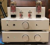
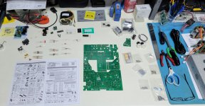
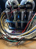
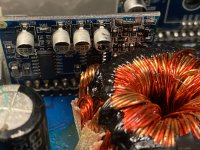
I figured the best place to start would be at the bottom of the chain and slowly work my way up. After digging around for several months, I came across the TU-8200R Amp kit along with the TU-8500 Pre-Amp kit. I found it intriguing as it was a full-on, build-it-yourself sort of kit that came with everything. The reviews on it were outstanding, and the documentation on component upgrades was well defined and easy to follow. The only pitfall was that some of the upgrade components were no longer available, such as the AMTRANS components, but c'est la vie. The biggest improvements seemed to come from using Mundorf coupling caps and Lundahl transformers anyway, so that was what I opted with for the final build. Tube rolling will come later. Ordered through TubeDepot and then waited for the brown Santa to show up in his trusty delivery van.

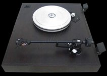
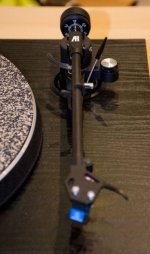
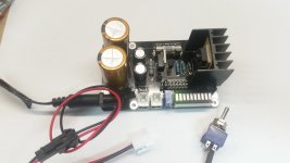
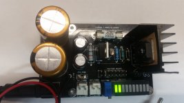
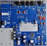
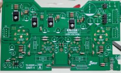
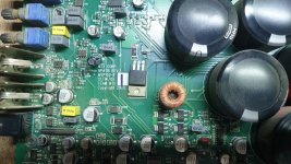
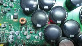
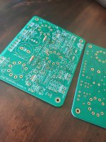
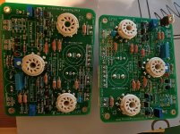
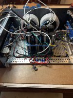
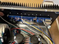
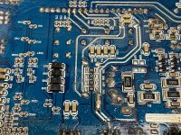
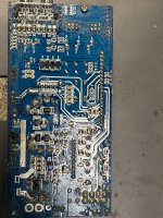
I did my process a little backwards, starting with the pre-amp first as I was waiting for my Lundahl transformers to come from VKAudio. Out of the box, this thing is a solid work of engineering. The chassis was remarkably clean in design and fit together well. I may, at some point, disassemble and have the chassis powder coated a different color, but it's great as it is. The PCB is laid out very well, all the components were grouped in nice, organized baggies, and the instructions were very clear to understand. Now, I'm an electronics engineer by trade (digital, not analog), so following a schematic and PCB layout is a simple thing for me. Not to mention that I have a helluva soldering station. PCB assembly and soldering didn't take long, and within a couple hours I had the whole thing put together. Slapped in the J/J tubes, connected my Technics 1200 turntable to it, and hooked it up to an old Pioneer SX-980 with Kenwood KL-777A speakers and then let 'er rip.

I let the pre-amp run for about 2 hours just to let things settle in and then dropped Tom Petty on the platter. Even with the tubes barely even run, the difference was immediate. The sound was warmer with vocals that were more in the foreground. I played this album and then moved on to my next favorite, Pink Floyd - Wish You Were Here. Shine On You Crazy Diamond (Parts 1-5) is my quintessential sound system test. For me, this track reveals the soundstage and depth of a sound system, or even the capability of individual components, and let me tell you, the TU-8500 did not disappoint. I went with this setup for several days, and with each passing hour the pre-amp continued to provide subtle improvements in sonic and tonal quality. I now realized I needed to get the amplifier built!

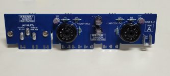
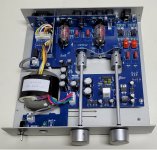
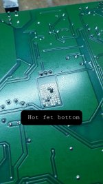
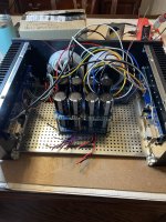
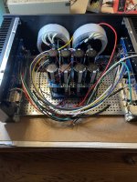
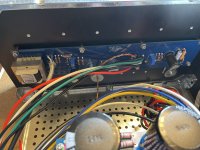
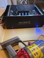
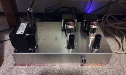
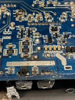
Thanksgiving intervened and I had to do all that family stuff. While I always enjoy being with family, I was quietly preoccupied with wanting to put the amp together. Our office was closed for Black Friday so I headed in and began the process of assembling the amplifier in peace and quiet. Again, all the details were impeccable and assembly was completed in a matter of hours. I'm a bit of a perfectionist, and since the tubes are exposed in this unit, I spent a little extra time making sure that the tube sockets were level and even. Unfortunately, during my final assembly of all the PCB units, I forgot to solder the bridges on the bottom of the input/output board which left me a little perplexed when I fired up the amp and had no sound. A few muttered curse words and 45 minutes later, all was good.

I've always heard from people that 10 watts of power from a tube amp is like 50 watts of power from a solid state amp. I always took these comments with a large degree of skepticism since I've always argued that "Watts is watts." I guess that it's true that wattage is a pretty stable measure of audio output. But let me tell you right now... This little amplifier that only runs 8 watts per channel sounds better than my 100 watt per channel Onkyo receiver (in stereo mode) running through a set of B&W 603 S2 speakers! Of course, the Onkyo running in 7.1 will simply outmatch almost any 2 channel amplifier for range and soundstage, but in 2 channel mode I would take the little tube amp every time. There is no absolutely no hint of hiss or hum at idle with no input, even with headphones on. It is dead quiet until you feed the signal back into it and then it just fills the room.

I just couldn't believe the quality of the sound the TU-8200R produces at a pretty solid listening level. It's certainly loud enough that I can feel immersed in the music, and that even with the TU-8500 pre-amp on a flat 1x gain on the inputs. I haven't even turned it up to 3x yet, and from what I've read so far, the amplifier can certainly handle the higher input levels without becoming too distorted. I may give that a try tonight and see how well it handles. I expect it may pick up some signal noise, but I can't say until I give it a spin.

As an aside, the amplifier works great with a set of high quality, high impedence headphones. My Sennheiser HD-650, which works fantastic with my DarkVoice 336SE, sounds fantastic with the TU-8200R. Of course, you don't buy an amp like this just to plug in a set of headphones. It's just nice to know I'm not losing anything in sonic quality. My DarkVoice picks up stray interference with the volume turned up and no live signal coming in, but I think that has more to do with being pretty close to my monitors on my computer desk. I've moved it to another location and that noise disappeared. However, I do not get any noise with this combination of pre-amp and amp sitting in the same location, so the DarkVoice might need a little more input filtering. I did install the PS-3249 DAC module and that works just as I would expect. I don't expect to use it much, but it's there if I need it and it doesn't take away from anything when it's not plugged in.

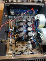
Overall, this has been an absolutely fantastic kit build. It's a pretty easy go, provided you have a resonable level of skill with soldering. The rest is just following instructions. I did take the amp apart and installed the original transformers just for a quick listen, and the sound did have a little bit of dryness to it. I can't quite explain it, but it felt like some of the low frequencies were a little muddled and washed out which took away from some of the depth of the soundstage. I can't say for highs since I have tinnitus (too many years of concerts and loud car audio) and can't hear anything above about 12,000 Hz, but the range I can hear still seemed to be pretty clear and sharp.

Tube equipment is clearly the way I need to go in the future. I got my feet wet and I'm now ready to jump in. Just for grins, I've already ordered and received the TU-8550 pre-amp and will soon order the TU-8900 amplifier. I'm ejoying the building of these kits and have been absolutely floored by the sound quality of both the pre-amp and amplifier. I mean, for the price you just can beat it. And with the ability to swap power tubes in the TU-8200 between the 6L6, KT88, EL34, 6550, and possibly even the KT90 (I don't know if KT120 would work), all with auto biasing, it makes tube rolling a fun (albeit potentially expensive) adventure. But if you're going to tube roll, then this is a great way to start out.

Again, many thanks to Victor Kung, TubeDepot, and also to Elekit and the infamous Mr. Fujita. Excellent work by everyone in bringing this exceptional product to market and making it affordable to the average hobbyist. It provides entry level access to quality tube audio equipment as well as a platform in which to build a solid foundation of understanding how tube audio equipment works. Well done!!!

TL;DR

I bought the Elekit TU-8200R amp and TU-8500 pre-amp kits along with Lundahl transformers and Mundorf caps for the amp. I assembled them and they are *******' AWESOME! Do yourself a favor and get these for yourselves. You can't beat the quality, especially for the price.

Attachments

  • 20221126_151320.jpg
    20221126_151320.jpg
    613 KB · Views: 301
  • 20221114_172426.jpg
    20221114_172426.jpg
    656.9 KB · Views: 249
  • 20221114_172452.jpg
    20221114_172452.jpg
    180.5 KB · Views: 226
  • 20221115_092119.jpg
    20221115_092119.jpg
    728.8 KB · Views: 264
  • 20221125_120231.jpg
    20221125_120231.jpg
    389.4 KB · Views: 228
  • 20221125_145949.jpg
    20221125_145949.jpg
    422.4 KB · Views: 241
  • Like
Reactions: Robin De Wolf

Farnell LT30-01 dual bench power supply faulty?

Hi,

I have picked up recently a vintage Farnell LT30-01 dual bench power supply from a well known auction site.
It has two fully independent channels capable of delivering 30V at 1A max.

I tested it today and I think one channel is not behaving correctly (maybe usable but I do not think it is ok).

I want to use current limiting facility.
I set both channels to CV (the switch underneath).
I set up first the desired voltage to say 5V. Then I set up the current limit. I connect 10Ohm to the output. and set the meter to show the current.
I expect to get 0.5A which I do. Then I adjust the current limit downwards until the measured current starts to drop. This is my limit setting.
I verify the operation by replacing 10Ohm load with a smaller one. The meter shows still 0.5A but the voltage drops accordingly to Ohm's law.
This is what I call proper operation.

The other channel: I set up the voltage, connect my 10Ohm resitor and proceed with the current limit setting. With this channel I can set the current limit to any value between 0-1A and the PS seems to increase the voltage if I exceed 0.5A which I do not like very much.
Of course I can still set up the current limit to 0.5A (and verify that the voltage is still 5V) and I can test the limiter by trying a lower value resistor - which seems to work ie t keeps the desired current but the voltage drops.

Still, somehow I do not like the idea that if I accidentally turn the current limit pot my voltage will increase too.

Is the unit faulty?

It is not my policy to take the advantage of the seller/force him to pay return postage etc using fleabay buyer protection scheme. BUT I also do not wish to pay for a unit advertised as working and then spend time fixing it...
I'd rather be soldering amplifiers in this time.

Wear on speaker cap coating

Hi there,
I saw a couple of vintage Coral speakers for sale. They look in good shape in the picture, except that the center caps, which are supposed to look like polished silver, have a dull look for most of the surface, except for the rim. See pic.

Shall I be concerned about the sound quality? Aesthetics are secondary.
Shall I be concerned about further degradation? E.g. is the silver coating detaching and will it eventually flake off?
Is there some kind of service to restore the caps to their original sheen or replace them for a reasonable price?

Thank you.

Attachments

  • coral_cap.jpg
    coral_cap.jpg
    103.8 KB · Views: 85

Need POWER SUPPLY schematic for Threshold FET 9 preamp

I found a Threshold FET 9 preamp at a recycling center (!!!), no power supply. It's in fantastic shape and I have hooked it to a friends power supply and it works. Threshold power supplies are few and far between and not cheap. I would like to build my own. I could backwards engineer the original, or if anyone has a schematic for the original or if there are any plans floating around for an upgraded power supply, that might be a good way to go. It's 18 volts DC but I'm not sure of the amps or wattage required at the output as I can't find much on either unit. The power supply does have a sticker that notes input power select of 120 vac or 240 vac with a max drain of 10 watts. The fuse for 120 vac use is .5 amp, slow blow or 1/4 amp slow blow for 240 vac use.

Any suggestions would be appreciated.

Thanks,

Eric M.

MTX 81000D LED 238 does not turn on and no audio

Hello friends! Thank you for allowing me to continue being part of the forum. On this occasion I have in my hands an amplifier of the brand Mtx model 81000d in which I received an irf540 in the output stage, of course it was blown up. The problem is that it does not generate audio. LEDS 399 and 463 turn on, but there is a current consumption of more than 4 amps and the fet that is attached to the board is very hot, I have a sawtooth gate pulse, but I understand that it is normal, at least Turn on the amplifier my supply voltage goes from 12v to 9v, I checked the fet that is on the board and it reads well, tomorrow I will lower it and get the HCPL3120, in the same way I measured them and they seem to be fine but I will try to get them, thank you your help and patience... regards

Attachments

  • 20221123_203723.jpg
    20221123_203723.jpg
    469.9 KB · Views: 153
  • 20221123_203601.jpg
    20221123_203601.jpg
    394.6 KB · Views: 129
  • 20221123_185459.jpg
    20221123_185459.jpg
    513.1 KB · Views: 147
  • 20221123_185445.jpg
    20221123_185445.jpg
    453.6 KB · Views: 137
  • 20221123_185452.jpg
    20221123_185452.jpg
    589.2 KB · Views: 148
  • 20221123_185441.jpg
    20221123_185441.jpg
    587.5 KB · Views: 219

When to use a soft start circuit?

I've read lots of information that says that once you roughly pass a 300VA transformer, that you should include a soft start in your amplifier. My question is this - is it really needed when you're on 230V like in Europe? Most of the working examples show really large in-rush currents, but they are almost always on 115V AC. If 300VA+ is roughly the point for 115AC when it's needed, wouldn't it be more like 600VA for 230VA? Sorry if it's a remedial question, but since the current is half at 230V AC, it seems like a soft start wouldn't be needed at the same threshold.

Zen V9 - Alternate Power JFET choices?

Hello,

I would like to experiment with a Power JFET build using the Zen 9.

https://www.passdiy.com/project/amplifiers/zen-variations-9

I'm looking to build it using Lovoltech LU1014D but want to use a current production part.

Can anyone suggest current SiC production parts?

Poking round I found these:

UJ4C075060K3S (N-OFF)​

https://www.mouser.ca/ProductDetail/UnitedSiC/UJ4C075060K3S?qs=hd1VzrDQEGjVfGB6b9i7uA==

UJ3N065080K3S (N-ON)​

https://www.mouser.ca/ProductDetail/UnitedSiC/UJ3N065080K3S?qs=byeeYqUIh0OYOU7Cis0jMg==

Which Power JFET is preferred N-ON o N-OFF?

New Flagship DAC the AK4499EX to Debut at the IPS / HIGH END® Munich2022 Show

https://www.akm.com/eu/en/about-us/news/2022/20220420-ak4499ex/

It looks like we will be getting a new "DAC system", consisting of two chips, one doing the DSP & ΔΣ modulation and one being the actual DAC, much like the previously announced pair of AK4191 & AK4498.

So the DSP & ΔΣ modulation will be performed by the previously announced (but never really seen by the general public) AK4191, and the DAC will be done by the new part AK4499EX (which looks like a 2-channel version of the AK4499 with the digital components removed).

1650532364316.png


1650532331004.png


So AKM is slowly making a comeback..

Attachments

The Ikea Symfonisk speaker conversion project

I am starting this new thread with the hope fellow forum members will benefit from the work already done, and possibly can help me with the work still ahead.

I too am working on the Ikea Symfonisk hack, mostly because we are already heavily invested into the Sonos system for casual listening.

In my office,I used to have a Sonos Connect:AMP to drive two homebrew bookshelf speakers, but I got curious after reading about the Symfonisk hack. So I bought one, opened it up and hooked it up to the drivers directly and this sounded way more detailed to me. So I bought a second one and from thereon, the project got stuck.

But not before I got a friend to design a 3D printable enclosures to mount the Symfonisk board on the back of the speaker:

(It's a real pity the forum engine ignores the orientation property)

We even added the Sonos signature button panel:


It's got that 3D chique finish, but it's on the back, so nobody sees is. I have to lookup the .STL files and I will post them here later.
As is well known, the Symfonisk is a bi-amp system, driving the tweeter and woofer with separate Class-D amplifiers. The cross-over filter is probably digital, since Sonos offers a feature they call Trueplay, allowing to tune a speaker for the room it is place in. It's sold as a feature, but it's probably a work-around for the bug of using sh*tty drivers in a tiny box.

Now I wonder if this feature can also be used to compensate for a different set of drivers. To do that right, the digital cross-over filter must not only be able to adjust the levels on both sides, but also the cross-over frequency.

And this is where the project is stuck now: I want to measure the cross-over properties, but I lack the experience. I own a Rohde & Schwarz UPL audio analyzer and I have a Sonos Connect I can use to inject the UPL's signal into the Sonos system. There will be delay, so sweeping will not be possible, but it can also use white noise, so that will be the next-best thing.

Is there anybody here who can help me set up this measurement?

Attachments

  • IMG_4122.jpg
    IMG_4122.jpg
    903.9 KB · Views: 1,005
  • IMG_4123(1).jpg
    IMG_4123(1).jpg
    457.4 KB · Views: 1,126

Ferrograph F307 Mk 2 transformer failure

I have had my Ferrograph F307 Mk2 from new having purchased it as a student in 1975. So I'm rather fond of it!!
It has developed a fault - the mains fuse blows on power up and a local vintage amps repair firm has confirmed what I thought - the main transformer has failed somewhere deep in the windings.
Replacements are not available so I am looking at a possible rewind. The schematics (attached) indicate an output voltage between A and B of 70V but do not confirm what it is between X and Y. Am I right to think that it's the same?
Ferrograph F307 wiring diagram.jpg
between X and Y. Am I right to think that it's the same?

Attachments

SS amplifier dissipating 120W using internal porous ceramic heatsinks.

I have previously built amplifiers dissipating over 32W of heat using porous ceramic heatsinks.
https://www.diyaudio.com/community/...and-heatsinks-using-ceramic-heatsinks.380763/

I wanted to rebuild my Ovation SX 15W per channel class-A amplifier which dissipates 120W as heat. The original SX build used an off the shelf case which was large and heavy so I designed a new one using the technique I previously used in my “headinclouds” KGSShv Carbon ES headphone amplifiers dissipating about 32W. The cases are all 3mm sheet aluminium alloy and the heatsinks are porous ceramic with adhesive pads. The SX rebuild adds two ripple eaters, volume and balance controls and headphone feed while being smaller and lighter.
I allowed 3W dissipation for each Amec Thermasol FCH505010T, so 22 dissipate 66W per channel for a reasonable temperature rise. They are simply stuck on to aluminium plates holding the power transistors and forming part of the case. Of course the heatsinks are now internal so the case needs a good updraught to allow the heat to escape. In practice the temperature rise is similar to the original large aluminium finned amplifiers. The area near to the power transistors runs at around 50°C and the outer heatsinks 44°C.
DSCF3506.JPG
DSCF3531.JPG
P1000669.JPG
P1000673.JPG
The case is 375W x 320D x 170H (inc. feet) [14.75 x 12.6 x 6.75in]

Use of transformer for unbalanced RCA to Icepower balanced input

Hi.
I've built a pair of Icepower 200asc amps, and am using these in a biamplified system, with a DAC feeding an active crossover (RCA unbalanced outputl
The 200asc has a balanced input. Since I already have a pair of suitable transformers from another project (Jensen JT11-P1), I'm hoping to utilize these to converth the unbalanced input for use with the balanced amp (FYI, I am not interested in an active solution, nor passively tying one of the 3 pins to ground).
BTW, there are a Red and Brown lead going into the transformer and Black,White, Yellow and Orange leads coming out. I do not see any labels for them).

I see in the manufacturer's diagram (attached) that they show an RC network (13k/620pf) across the output leads attached to pins #2 and #3 (which is also tied to pin 1/screen, input shield).

Q:: Are all these connections and Res/Cap components shown in the diagram necessary and correct for my application?

I have seen other diagrams online that differ greatly, but noticed that Jensen refers to this one as "Best", which I interpret as only one way.

Thanks for any guidance in this effort.

Attachments

  • Screenshot_20221126-062049.png
    Screenshot_20221126-062049.png
    123.3 KB · Views: 544

Differential Current Probes

Hi,
my name is Alfred Rosenkraenzer, I worked 36 years as a design engineer, mainly on analog and digital signal designs.
Now I am on early retirement.
I designed two differential current probes to measure the current in a shunt resistor with a scope. These are pretty helpful if you like to measure eg the current in the emitter resistors of an audio power amplifier, or at switching power supplies.
There are two articles about them in ELEKTOR:
https://www.elektormagazine.com/magazine/elektor-201609/39807
https://www.elektormagazine.com/magazine/elektor-159/59112

Attached are some screen shots from the emitter resistor of an amp.
On SCR01 the yellow trace is the output of the amp at 8 Ohm, purple the upper emitter current.
Note the difference in bias current between SCR02 and SCR03. Look at the end and the start of the half sine.

If someone is interested I can send you more info.
I still have some blank boards which I can sell.

Best regards
Alfred

Attachments

  • SCR01.PNG
    SCR01.PNG
    11 KB · Views: 98
  • SCR02.PNG
    SCR02.PNG
    7.9 KB · Views: 106
  • SCR03.PNG
    SCR03.PNG
    7.9 KB · Views: 104
  • SCR04.PNG
    SCR04.PNG
    10.6 KB · Views: 101

el34 quad tube pp guitar amp: series /parallel heater wiring for half power Q/A

hello,

I have an amp that uses series parallel heater wiring for the el34's
the left to power tubes were one wired lot and the right side were the other wired pair (please see original schematic below)

to save cost for a quad set of tubes I opted to run the amp at half power on only the two center tubes V10, V11 by wiring the heaters as a series/parallel pair, rebiasing and running the output impedance at half. this has worked fine.

I am going to pass the amp on now so I am thinking to wire V9, V12 heaters as a pair so the new owner can purchase a quad set of el34's and run the amp at full power should they choose.

My question is in the design are the V9,V10 and the V11,V12 heaters wired together for the correct voltage because the are situated close to each other to make wire routing easier and saves on wiring ....

Or is it a design rule effecting noise and interference that heater wiring in series parallel arrangement has to be at each end of the output transformer (in quad pp designs)?

please note: I am only inquiring in regards to the heater wiring arrangement,

...........to simplfy can V9,V12 be run as one heater series/parallel pair and V10,V11 be run as the other heater pair (with re wiring of course) without causing poor effects or problems?


thankyou

Attachments

  • screenshot-www.ozvalveamps.org-2022.12.10-19_01_21.png
    screenshot-www.ozvalveamps.org-2022.12.10-19_01_21.png
    53.6 KB · Views: 134
  • screenshot-www.ozvalveamps.org-2022.12.10-19_15_28.png
    screenshot-www.ozvalveamps.org-2022.12.10-19_15_28.png
    79.7 KB · Views: 132

Ladder Attenuator: Why a calculation with specific load, and even "no load"? (Elma)

Hi friends
I am still struggling to understand the math behind ladder attenuators. I once thought it would be easy, but nope, not really. (Not if following/listeningn to the masters at least).
So I have this cool ladder attenuator calculation sheet from Elma, but it's too cool for me: Why are there those "Ladder (no load)" and "Ladder (with load)" options?

Haven't ever seen anything like that although I've looked at I'd say most of the products available...
I believe Master Salas already explained it (here), but I'm completely overwhelmed.
What Load-impedance should I go with, and — why?
(excel calcsheet included as zip-file)

Thank you

Attachments

Making cases and heatsinks using ceramic heatsinks.

Cases and heatsinks are a problem for DIY builds.

I made quite a few amplifiers with thick machined front panels, heavy finned heatsinks and aluminium cases. Such parts need machining and tapping.

I devised a way of making cases, which eliminated these problems and made for easier case design, lower costs and quicker builds.

Cases

Made from sheet aluminium alloy of preferably 3mm so only single sheet of material needed.

Depending on the facilities you have available these can be made manually. I get the parts laser cut by a company which will also supply the material. Alloy 5251 lasers and anodises well. The case parts need holes to be countersunk where necessary and are then taken for surface finishing, (bead blasting and anodising in my case).

I then take the front panels to be screen printed with the graphics I provide. The assembly is with corner posts and angle brackets cut and drilled, and bolted together. I only drill and tap corner posts to attach base and top panels. The case is basically a box with a front panel on to cover the front of the box.

Heatsinks

I became aware of porous ceramic heatsinks and realised that these small, light self-adhesive items would solve problems. I bought a few and tested to see if they did what was claimed. A single 50mm square of 10mm thick could dissipate 5-10W stuck on sheet aluminium. To make heatsinks you only have to bolt the semiconductors directly to the 3mm plates and place the ceramic heatsinks as needed.

Edit; a link to these was omitted, http://www.amecuk.co.uk/ Element14 has them in many countries.

https://www.newark.com/c/cooling-thermal-management/heat-sinks?brand=amec-thermasol

They are not expensive, and with a range of sizes you can arrange heatsinks of different shapes. I was concerned that they might unstick but the opposite has been true, they are hard to remove.

They are not pretty and can be easily chipped so I contain them inside the case and organise slots above and below to act as a chimney to allow convection. This works well and they do not run hot. The porous ceramic devices are very effective.

I have found that this method is much easier to procure and build. The amplifiers built this way can be smaller and lighter. These techniques can be adapted to any case whether needing heatsinks or not.
I should say that these heatsinks are small and they don't weigh much but that each amplifier on either side of the case dissipates about 14.5W and the heatsinks are only warm. (Edit; Further explanation a few posts below)

Attachments

  • P1090504.JPG
    P1090504.JPG
    387.5 KB · Views: 574
  • P1010241.JPG
    P1010241.JPG
    206.8 KB · Views: 556
  • P1090506.JPG
    P1090506.JPG
    257.4 KB · Views: 476
  • P1090495.JPG
    P1090495.JPG
    502.4 KB · Views: 518
  • Like
Reactions: stretchneck

Fixing Behringer DEQ 2496 "flashing screen" and similar

I have 7 Behringer DEQ 2496 units in continuous usage in 3 different systems. They conveniently allow me to do a wide range of adjustments I need to do, including parametric EQ, graphic EQ, bass limiting, level adjusting, level monitoring, and RTA. And all with midi controllable setting memories. They are useful in multiway as well as (my kind of) multichannel systems.

Around 2013 I discovered I could even use them to replace the Behringer DCX crossovers I was then using. By aligning two "low pass" filters in the parametric section, you can get an LR24 lowpass response, and likewise for the highpass response. This enabled me to use full digital I/O because the DEQ have full digital I/O whereas the DCX only has digital input. Then I can use the DAC's of my choice (so long as DAC latency is corrected for each way and each supported sampling rate...).

I started with one unit in 2005, added the second one in 2008, and on and on. But by 2010 the first one failed, and for me they seem to have lasted 5-10+ years (some of the latest new ones I bought are still going fine, and I've improved the ventilation with higher spacers, and they seem to have improved the parts quality a bit since 2005).

I never fixed any, I just bought new ones like candy as the old ones failed. I saved them in a big pile for "later when I have time to fix them."

I think the time has come to start trying to fix them. They are unavailable new and the used ones (I have sadly learned) may be nearly "used up" if they work at all. I got exactly one year's use out of the last one I bought on ebay for $200.

The latest one (a year after purchase on ebay) has now died with the "flashing screen" problem. When the unit boots up you never get the copyright screen or anything just a flashing screen. Something like half of the ones in my dead pile died with that problem. Others may have the "blank but lit screen" problem, or the "dead as a doornail" problem. I suspect most or all of these problems are power supply related.

Sadly there is no schematic and no service manual. I have found a multipage schematic of some kind but I haven't seen the power supply on it.

I am going to be taking one apart today or soon to see what I can figure out.

45 DHT Filament Question . . .

Hi folks. Quick question about DHT filaments. I designed a build to incorporate two switches, one to fire up the filaments, and the other to pass the B+. To my chagrin, I just discovered after turning b+ off, I'd forgotten to turn the filament switch off last evening. Unfortunately, I'm talking vintage 45 globes. Duh. :-( As a general proposition, how much damage have I done? (The amp sounds fine right now.)

F6 Mosfets running too hot?

Good morning to the group,

I’m a newer builder and reached another challenge there perhaps someone can share some of their expertise. My latest project is the First Watt F6. I built it and now am in the final stages of biasing the channels. With (2) meters clipped the source resistors and(2) others connected on the speaker outputs, I thought I was golden because I kept watching my heat sink temps were as I ran the bias up and we’re just nicely warm, never hot at 47*C. As I continued to raise the bias, finally stopping at 565/575mv and offset set @ +\- 1-2mv. Everything seemed nice and stable. So after a few different days of monitoring the bias and offset remaining fairly stable. I connected some test speakers, there’s no hum or noise so I played some music. It sounded good. It’s when I went to take my test equipment off I noticed the plastic on my test leads on both channels Source Resistors was literally melted. Shame on me for not noticing sooner and not checking the mosfets sooner. I just assumed if the heatsink is cool, so is what is attached to it. I got my infrared and started shooting temps on the mosfets. THEY ARE HOT, very hot @ 69*C. I immediately backed down the bias on both channels to around 350mv. After some time i checked temps again and they are still super at at almost the same temp 68/69C. Even the hold down washers are extremely hot. I never noticed this on the F5T or Aleph J amps and I will check those this weekend. I checked to be sure my screws were tight and they are. It almost seems like I’m not transferring the heat from the mosfets to the heatsinks. Is that Possible? I guess I should ask, do I have an issue to address?

Attachments

  • AAC45857-0279-4F2E-B224-A1D6232C34CB.jpeg
    AAC45857-0279-4F2E-B224-A1D6232C34CB.jpeg
    939.6 KB · Views: 168
  • 128ED44D-0A09-47F6-9243-DDAA1318663B.jpeg
    128ED44D-0A09-47F6-9243-DDAA1318663B.jpeg
    921.3 KB · Views: 157
  • 9C67B777-1080-4DBC-9B4F-45B1168DB21B.jpeg
    9C67B777-1080-4DBC-9B4F-45B1168DB21B.jpeg
    892.3 KB · Views: 151
  • 8D8ED766-C60C-4B7E-AA10-06A3C28EC6CF.jpeg
    8D8ED766-C60C-4B7E-AA10-06A3C28EC6CF.jpeg
    881.1 KB · Views: 159
  • 6C73E74A-11D2-46AB-BB7E-5661C192C10F.jpeg
    6C73E74A-11D2-46AB-BB7E-5661C192C10F.jpeg
    679.1 KB · Views: 152
  • BF299213-056D-4C5D-B89B-F342CFE5780D.jpeg
    BF299213-056D-4C5D-B89B-F342CFE5780D.jpeg
    660.1 KB · Views: 155
  • 7C476357-5607-48FA-875D-2A28063901CA.jpeg
    7C476357-5607-48FA-875D-2A28063901CA.jpeg
    661.3 KB · Views: 158
  • BECEB41B-C2DC-420F-A397-DD29D3303443.jpeg
    BECEB41B-C2DC-420F-A397-DD29D3303443.jpeg
    428.1 KB · Views: 156
  • 81A52B2E-282B-4548-A879-692C4F5FD3CA.jpeg
    81A52B2E-282B-4548-A879-692C4F5FD3CA.jpeg
    759.6 KB · Views: 185

Parallel 3094 Design

Greets & thanks to the community, been through a lot of threads that have proven quite helpful.

Hoping I could get input on whether this board layout is functional/optimal, first timer here.

Power comes in via a DC-DC converter on J4 that's mounted to a seperate board.

My biggest concerns are whether the set pin layout is ok, the datasheet suggests a guard ring & I'm not fully sure I've accomplished that here. That and there aren't any great examples of a parallel 3094 layout, so just horked ideas from the 4x 3045 design on AD's website.


I might have to break the whole thing out into a seperate sub-assembly so that I can follow the exact layout of the eval boards? This area is all the space that's available on the mainboard. Are there any designs floating around the forum that would be good examples of a parallel 3094 layout?

Cheers & much appreciate all help and suggestions

Attachments

  • 3094 panel.png
    3094 panel.png
    32 KB · Views: 125

Passive component matching?

Just curious if folks actually go through the hassle of measuring and pairing resistors, capacitors, and transistors used in signal paths in order to help keep everything internally balanced when assembling kits. Since many of the preconfigured kits such as Elekit tend to use 5% tolerance resistors, I was not very surprised to see large swings in resistance between the individual components. There are obviously some locations where a slight variance wouldn't be critical, like for the power supply. However, it seems that anything directly in the signal path could exhibit a balance issue if the passives had enough accumulated variance.

With OCD in full swing, when building my TU-8200, TU-8500, and most recently my TU-8550, I did take the time to value match as many pairs as possible. I don't know how much it really helped, but to my ears I don't notice any balance issues.

Anyway, just wondering if anyone else did this.

6HJ5 SET

I just wanted to share my successful build using the 6HJ5 wired as a triode. These tubes are cheap and rugged, and oh yeah they sound great. The driver is a 6N7 with both triodes in parallel.

I have a SS Slewmonster and Mullard 5-20 monoblocks so this amp is my "colored" sound amp. It has that warmth of a 300b amp. I highly recommend people to go ahead and not be afraid to use this tube for audio. I know George has used them in Pete's big red board but I wanted to share the success of it wired as a triode.

-bird

Attachments

  • 20160322_190105.jpg
    20160322_190105.jpg
    282.6 KB · Views: 2,308

On the directivity of dipole tweeters

There have been some attempts lately to make dipole tweeters work up to high frequencies with constant directivity. How high can we go, if the tweeter housing is already almost as small as its radiating area?

I would like to demonstrate the issues involved with an idealized 1 inch circular tweeter. I am using some Boxsim simulations to show things detached from specific driver peculiarities like FR and dome breakup modes.

Let’s start with the mathematical dipole model – first for a dipole distance of 2,5 cm to keep things within 20 kHz:

attachment.php


This is equivalent to this Linkwitz figure.

A 1’’ tweeter would have a physical diameter of at least 2,5 cm. This would lead to a dipole distance of 1,25 cm. As a 2-point source this would sim like this:

attachment.php


Of course a tweeter is no 2-point source. Let’s first move to a dipole point source on a 25x25 mm square baffle (Boxsim can’t do circular baffles).

attachment.php


We can see that the dipole peaks are slightly lower in frequency because a 25x25 mm baffle is more like a 28 mm disc than 25 mm. More important by far is the change in directivity that is introduced by the baffle. The dipole 8 gets sort of slimmer.

Since a real tweeter is not a point source on a baffle, we make the cone/dome/foil as wide as the baffle. Note that our model is working as a dipole membrane in a housing with no depth now. Any real world tweeter would have to be larger:

attachment.php


Note how the dipole 8 gets even slimmer than before and how the dipole peaks move to even lower frequencies. Strangely the 60 deg peak is at a lower frequency than the on-axis peak. Same for 30 deg. How come? The next diagram shows why by overlaying the last two diagrams:

attachment.php


The wider source starts to beam – lower in frequency at wider angles. From a certain frequency up the directivity of the tweeter is no longer controlled by the dipole function but by the tweeter diameter. The next diagram shows this relationship at the first dipole peak:

attachment.php


A monopole tweeter would have a main beam to the front of almost the same contour as the figure 8 of the dipole. This would be true for any driver whose radiating area is as large as its baffle – regardless of size. Any attempt to manipulate the radiation at the sides of the baffle is quite fruitless for frequencies above the first dipole peak – they don’t show up any longer at the sides.

The only cure is to move the first dipole peak up by making the tweeter smaller. Above the first dipole peak all compact drivers will move from the (constant) directivity of the dipole 8 to the frequency dependent directivity of a beaming driver.

That’s how I see it. 🙄

Attachments

  • dipol 25_1.gif
    dipol 25_1.gif
    7.8 KB · Views: 4,396
  • dipol 25_2.gif
    dipol 25_2.gif
    7 KB · Views: 4,394
  • dipol 25_3.gif
    dipol 25_3.gif
    7.1 KB · Views: 4,360
  • dipol 25_4.gif
    dipol 25_4.gif
    7.1 KB · Views: 4,318
  • dipol 25_5.gif
    dipol 25_5.gif
    8.7 KB · Views: 4,339
  • dipol 25_7.gif
    dipol 25_7.gif
    7.3 KB · Views: 4,301
  • Like
Reactions: Juhazi

Help with REW subwoofer placement vs Mic placement - different SPL reading

Hi All!

this is the first day im using REW.
From the youtube tutorial I've seen, people say it doesnt matter if you put you mic at you sub position, or at the MLP. But I'm getting 2 very different SPL reading.
Can someone explain this to me?

Purple line: subwoofer at its 'OEM' position and Umik-1 at the MLP. noise is set to 75db with the rew generator with pink noise before taking the reading.
Red line: Subwoofer on couch, mic at the subwoofer 'OEM' position. Didn't change anything else except the position of the 2.

Those line are averages from 3 reading for each position. I was doing the exercice because I want to DIY a subwoofer, and I wanted to know if the spot I want to position it will be a good spot. Started measure the "OEM' spot and the MLP to see if they were the same....

So, should I move the sub around and keep the mic at the MLP, or should I keep the subwoofer at the MLP and move the mic around or the reading?

Thanks!

Attachments

  • Capture d’écran, le 2022-12-09 à 14.44.15.png
    Capture d’écran, le 2022-12-09 à 14.44.15.png
    96.6 KB · Views: 129

DB Drive NEO M4

Amp has a few issues with it .

First off the power supply fets are burnt .

The amp has 47 ohm gate resistors for the power supply fets .

The fets are marked CS50N

Anyone know what fets I can replace these with ?

Attachments

  • 35621669-3159-464E-9139-6DA3BA7B26B1.jpeg
    35621669-3159-464E-9139-6DA3BA7B26B1.jpeg
    562.4 KB · Views: 73
  • BBDB729D-49ED-40B1-8908-46888FE74339.jpeg
    BBDB729D-49ED-40B1-8908-46888FE74339.jpeg
    487.1 KB · Views: 67
  • 1BC36978-816C-4571-A3D3-E46A258C35E0.jpeg
    1BC36978-816C-4571-A3D3-E46A258C35E0.jpeg
    486.3 KB · Views: 69
  • 93BD1633-F2C6-41B3-84B9-8949082E19EA.jpeg
    93BD1633-F2C6-41B3-84B9-8949082E19EA.jpeg
    722.2 KB · Views: 70
  • 1EA967A3-1623-41A5-B3C3-34A053483048.jpeg
    1EA967A3-1623-41A5-B3C3-34A053483048.jpeg
    736.6 KB · Views: 75
  • 146873A9-E7D1-4C99-BED0-0444ABC6A87F.jpeg
    146873A9-E7D1-4C99-BED0-0444ABC6A87F.jpeg
    613.9 KB · Views: 75
  • 620C2A06-AD4A-4404-A0DF-BA44190C4D0A.jpeg
    620C2A06-AD4A-4404-A0DF-BA44190C4D0A.jpeg
    645.8 KB · Views: 79
Projects by fanatics, for fanatics
Get answers and advice for everyone wanting to learn the art of audio.
Join the Community
507,492
Members
7,874,453
Messages

Filter

Forum Statistics

Threads
405,585
Messages
7,874,453
Members
507,492
Latest member
Arthur Lin