Question regarding the proper way to ground the Modulus-86 amplifier
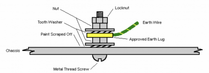
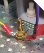
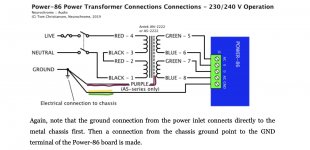
What I have done so far. I very slightly enlarged one of the many holes in the anodised? steel floor of the chassis just next to the toroidal transformer which is mounted vertically. I then sanded the underside of the floor around the hole and inserted a brass bolt 25mm x 4.8mm through a brass washer and inserted it through the floor. I added some star washers and some brass nuts – similar to the diagram below. I then crimped and soldered a ring to the purple transformer shield wire and added it to the post. I then ran a green and yellow striped 17 AWG wire from the green J1 receptacle GND on the Power-86 to the brass post.. Now this is where I have been getting conflicting “advice”. Person A claims that this is all I need to do. But Person B claims that I should not use the brass post at all and that I should discard it and just run the purple transformer shield and the wire from the J1 receptacle GND wire directly to the GND pin on the rear of the fused ON-OFF switch. But when I look at the Design Documentation for the Power-86 at page 18 (for 230/240 V operation) it seems to me that I should be keep what I have done with the brass post and now run say a 17 AWG green and yellow striped wire from the brass post to the GND pin on the rear of the fused ON-OFF switch? See the Screen Grab of page 18 of the Power-86 documentation. Appreciate some advice please.
What I have done so far. I very slightly enlarged one of the many holes in the anodised? steel floor of the chassis just next to the toroidal transformer which is mounted vertically. I then sanded the underside of the floor around the hole and inserted a brass bolt 25mm x 4.8mm through a brass washer and inserted it through the floor. I added some star washers and some brass nuts – similar to the diagram below. I then crimped and soldered a ring to the purple transformer shield wire and added it to the post. I then ran a green and yellow striped 17 AWG wire from the green J1 receptacle GND on the Power-86 to the brass post.. Now this is where I have been getting conflicting “advice”. Person A claims that this is all I need to do. But Person B claims that I should not use the brass post at all and that I should discard it and just run the purple transformer shield and the wire from the J1 receptacle GND wire directly to the GND pin on the rear of the fused ON-OFF switch. But when I look at the Design Documentation for the Power-86 at page 18 (for 230/240 V operation) it seems to me that I should be keep what I have done with the brass post and now run say a 17 AWG green and yellow striped wire from the brass post to the GND pin on the rear of the fused ON-OFF switch? See the Screen Grab of page 18 of the Power-86 documentation. Appreciate some advice please.
Attachments
You are doing the right thing.
Yes.
The earth pin (GND) on the AC receptacle must be connected to chassis for safety - your brass bolt as shown is good.
Purple on an Antek transformer is the shield, and can be thought of as chassis, so connecting it as you have is good.
GND on the PSU board needs to be connected to chassis as well.
If “advice” conflicts with the manual, follow the manual. Tom knows what he’s doing.
when I look at the Design Documentation for the Power-86 at page 18 (for 230/240 V operation) it seems to me that I should be keep what I have done with the brass post and now run say a 17 AWG green and yellow striped wire from the brass post to the GND pin on the rear of the fused ON-OFF switch?
Yes.
The earth pin (GND) on the AC receptacle must be connected to chassis for safety - your brass bolt as shown is good.
Purple on an Antek transformer is the shield, and can be thought of as chassis, so connecting it as you have is good.
GND on the PSU board needs to be connected to chassis as well.
If “advice” conflicts with the manual, follow the manual. Tom knows what he’s doing.
I think if you post this in billshurv's Modulus 86 build thread you will get the best possible input from Tom Christiansen himself.
https://www.diyaudio.com/community/threads/modulus-86-build-thread.267802/post-7062541
https://www.diyaudio.com/community/threads/modulus-86-build-thread.267802/post-7062541
Thanks for your replies Kevinahcc20 and 6L6 and thanks for your very clear and definite responses. To 6L6: About a year ago I very carefully followed your build guide for the Amp Camp Amp and to my shock and enormous relief it worked on the first 'turn on'!!! I regard your build guide as THE GOLD STANDARD when it comes to build guides! Multiple clear photos for each and every little step should be implemented by all designers if they want to increase sales, to reduce build failures (which I suspect are understated) and the number of annoying and time consuming questions about the build. Anyway thanks very much. Regards Geoff.
Multiple clear photos for each and every little step should be implemented by all designers if they want to increase sales, to reduce build failures (which I suspect are understated) and the number of annoying and time consuming questions about the build.
And...fwiw, Tom does respond rather quickly and has a build video for the Modulus 86:
Just sayin’
Best,
Anand.
As a result of the feedback I now have 3 wires running from my brass "grounding post" to:
1. A purple wire from the toroidal transformer (shield),
2. A green & yellow striped 17 AWG wire to the GND port of the green receptacle on the Power-86 J1, Pin 5, and
3. A green & yellow striped 17 AWG wire to the GND pin on the rear of the fused ON-OFF switch.
Now when I place one probe of my digital multi meter (DMM) on the male GND pin at the front of the fused ON-OFF IEC switch and I touch the other probe of my DMM anywhere on the floor of the chassis I get a "tone" indicating a closed loop.
This last "test" seems to me to indicate that the Modulus-86 is now grounded properly?
Well, you have confirmed that your chassis ground is indeed connected to the ground pin of your IEC (which has an integrated on/off switch and fuse). You should also confirm that your Power-86 J1, Pin 5 (which is labeled GND) is connected to your chassis ground and also to the ground pin at the front of your IEC. Instead of relying on the ‘tone’ of my DMM, I set the DMM to ohms and make sure that the resistance is near zero ohms indicating a direct short. It’s important to get this part of the construction right and it looks like you are well on your way to confirming that. If you would like more eyes to look at this, post a couple pictures. Judging by your previous posts (yes, I just took the time to read them), it appears that you have at least 1 if not 2 colleagues who are versed in electronics and at least 1 who has built a few Modulus 86 monoblocks. That’s good to have prior to your maiden voyage.As a result of the feedback I now have 3 wires running from my brass "grounding post" to:
1. A purple wire from the toroidal transformer (shield),
2. A green & yellow striped 17 AWG wire to the GND port of the green receptacle on the Power-86 J1, Pin 5, and
3. A green & yellow striped 17 AWG wire to the GND pin on the rear of the fused ON-OFF switch.
Now when I place one probe of my digital multi meter (DMM) on the male GND pin at the front of the fused ON-OFF IEC switch and I touch the other probe of my DMM anywhere on the floor of the chassis I get a "tone" indicating a closed loop.
This last "test" seems to me to indicate that the Modulus-86 is now grounded properly?
Best,
Anand.
Last edited:
Sorry. Today was a busy day so I didn't get a chance to respond until now.
Appendix A-5 of the Modulus-86 Rev. 3.0 design doc has the connections to the Modulus-86 board in schematic form. I describe it in text on pages 23-24. I show how to identify the windings on the power transformer on pages 12-17 of the Power-86 Rev. 1.2 design doc. I describe and show schematically how the power transformer then connects to the Power-86 board on pages 17-18.
Here's what I recommend for grounding:
"Each and every little step"? What do you consider to be a step? Some will need to be shown how to turn a screwdriver or how to bend a resistor lead with pliers. Others are perfectly content with a written description, such as, "Populate R1, R2, and R3". Yet others can assemble the board directly from the BOM or schematic without further help. I routinely assemble Power-86 and Power-686 boards from memory. I think I've found a pretty good balance in the design docs I provide. Just as authors of cookbooks assume you know how to measure out a cup of flour or mince and sauté an onion, I assume that you can populate a circuit board either from the BOM directly or from the assembly instructions that I provide ("Populate R1–R4 ..." on page 22 of the Modulus-86 design doc for example).
That's not to say that the documentation cannot be improved. Of course it can. But the vast majority of feedback I get on my documentation is about how thorough and detailed it is, so I don't see any need for immediate action here.
I don't have the exact number committed to memory but I've sold over 1600 Modulus-86 boards since 2014 when it launched. Around 20 of the boards that were built had issues. These were mostly "wrong part inserted", "part inserted with wrong polarity", or "solder blob in the wrong place" types of errors that I could easily spot via email. It's easy to accidentally swap a 33.2 kΩ resistor for a 332 kΩ one for example. I can count on one hand how many have had issues that were severe enough that I had the builder ship the boards to me for repair - which I did for the cost of parts and shipping, by the way. In one of those cases the builder stuffed all the ceramic capacitors but didn't bend the leads before turning the board over for soldering. So some of the capacitors fell out and he re-stuffed them without considering that they have different capacitances so it's important that you get them in the right spots. That was a tricky one to debug. Maybe one or two of the build issues could have been addressed with step-by-step pictures ... assuming the builder would have read the build guide that thoroughly. One or two out of 1600+ is a pretty low error rate, so I don't see any need for action here.
I highly doubt build errors/failures are understated. If someone spends a few hundred dollars in boards and parts, plus more if they buy a chassis, they (understandably) get pretty grumpy if the amp doesn't work in the end. So I don't think failures go unreported. I do think (judging by the number of Modulus-86 boards that have shown up in the Swap Meet over the years) that some boards don't get built and those go unreported.
Most of the questions I get are pretty good. The repeat questions are usually answered in the documentation, in the product description on my website, or in my Taming the LM3886 guide. I don't consider myself to be dumb and I do respond to feedback. So if I get the same question over and over I try to address it either in the documentation or on my website so I don't have to keep typing the same answer over and over because I don't really enjoy that either. But it seems that regardless of how much (or how little - TLDR is a thing) I write, how many pictures or diagrams I create, or how many build videos I produce, I cannot force anybody to read text, look at pictures, or watch a video - never mind expect them to pay attention to all the details within them. I also can't prevent people from seeking information on the internet and falling down a rabbit hole - like grounding. There's a lot of information on the internet and there's also a lot of misinformation. And some problems may have multiple correct solutions.
Rather than spending more time taking pictures I think there's more value in producing more videos. First off because that's the format that's expected these days. Secondly, because it allows people to learn at their own pace. If you find me long-winded, watch me at 2x speed. Or if you didn't quite catch that detail, rewind and watch again. I do not make any money from these videos. I have deliberately turned the YouTube monetization off so you don't have to sit through one ad after the next. That said, I have no control over what YouTube does, so I can't guarantee that there will be no ads.
It looks like Vimeo has changed the features on their free and standard plans so that they're now more usable. So I might start uploading the videos there too. With a paid Vimeo subscription I would pay for you to not have to sit through commercials. I wonder if there's any positive ROI there.
I have three videos that pertain to a Modulus-86 build:
Tom
Good job so far. Just adding precision: The steel plate isn't anodized. Brass hardware is not needed but also no harm. Plain stainless or zinc plated hardware would work just as well. That said, the brass is nice in that it doesn't tend to react with other metals much. You already have it installed so use it. I do like the use of proper crimp terminals and star washers. I'd finish the stack with a lock nut.What I have done so far. I very slightly enlarged one of the many holes in the anodised? steel floor of the chassis just next to the toroidal transformer which is mounted vertically.
Jim (@6L6) said it best: Follow the documentation.But when I look at the Design Documentation for the Power-86 at page 18 (for 230/240 V operation) it seems to me that I should be keep what I have done with the brass post and now run say a 17 AWG green and yellow striped wire from the brass post to the GND pin on the rear of the fused ON-OFF switch? See the Screen Grab of page 18 of the Power-86 documentation. Appreciate some advice please.
Appendix A-5 of the Modulus-86 Rev. 3.0 design doc has the connections to the Modulus-86 board in schematic form. I describe it in text on pages 23-24. I show how to identify the windings on the power transformer on pages 12-17 of the Power-86 Rev. 1.2 design doc. I describe and show schematically how the power transformer then connects to the Power-86 board on pages 17-18.
Here's what I recommend for grounding:
- The IEC mains inlet protective earth terminal must connect to the chassis. Preferably with a short wire to a chassis screw right by the connector. This is a safety thing.
- XLR pin 1 should connect to the chassis right at the connector. Usually chassis-mounted XLR connectors have a tab for this. Use it. XLR pin 1 then connects to pin 1 of the Modulus-86 input connector. This serves both as the ground reference and as the return path for the EMI/RFI filter.
- If the transformer has an electrostatic shield, its wire should connect to the chassis with a short piece of wire. On the Antek transformers, this wire is purple. On the Toroidy transformers it's yellow/green. Note that the shield is optional. If your transformer doesn't have a shield, don't worry about it.
- In the design documentation I show the ground terminal of the Power-86 connecting to the chassis. That's how I recommend that you connect it, but if you see my build video you'll notice that I've omitted that connection. That is because that build has XLR connectors and the ground reference is, thus, provided through the connection to pin 1 and chassis. If you use an insulated RCA connector you will need the connection from the Power-86 ground pin to chassis. And even if you use XLR connectors, having that extra ground connection doesn't hurt, which is why I haven't removed its mention from the design doc.
- All metal that can be touched by the end user (so volume knobs, connectors, exposed screw heads, chassis panels, etc.) must be grounded. If the chassis is all metal that's usually done by assembling the chassis, though, if the chassis is anodized I'd measure that all metal bits show connectivity to the protective earth pin of the IEC mains inlet.
They say that 85.2% of statistics are made up on the spot ... including this one. I suspect the same is the case for business advice. If you do have data to support your advice I'm all ears.Multiple clear photos for each and every little step should be implemented by all designers if they want to increase sales, to reduce build failures (which I suspect are understated) and the number of annoying and time consuming questions about the build.
"Each and every little step"? What do you consider to be a step? Some will need to be shown how to turn a screwdriver or how to bend a resistor lead with pliers. Others are perfectly content with a written description, such as, "Populate R1, R2, and R3". Yet others can assemble the board directly from the BOM or schematic without further help. I routinely assemble Power-86 and Power-686 boards from memory. I think I've found a pretty good balance in the design docs I provide. Just as authors of cookbooks assume you know how to measure out a cup of flour or mince and sauté an onion, I assume that you can populate a circuit board either from the BOM directly or from the assembly instructions that I provide ("Populate R1–R4 ..." on page 22 of the Modulus-86 design doc for example).
That's not to say that the documentation cannot be improved. Of course it can. But the vast majority of feedback I get on my documentation is about how thorough and detailed it is, so I don't see any need for immediate action here.
I don't have the exact number committed to memory but I've sold over 1600 Modulus-86 boards since 2014 when it launched. Around 20 of the boards that were built had issues. These were mostly "wrong part inserted", "part inserted with wrong polarity", or "solder blob in the wrong place" types of errors that I could easily spot via email. It's easy to accidentally swap a 33.2 kΩ resistor for a 332 kΩ one for example. I can count on one hand how many have had issues that were severe enough that I had the builder ship the boards to me for repair - which I did for the cost of parts and shipping, by the way. In one of those cases the builder stuffed all the ceramic capacitors but didn't bend the leads before turning the board over for soldering. So some of the capacitors fell out and he re-stuffed them without considering that they have different capacitances so it's important that you get them in the right spots. That was a tricky one to debug. Maybe one or two of the build issues could have been addressed with step-by-step pictures ... assuming the builder would have read the build guide that thoroughly. One or two out of 1600+ is a pretty low error rate, so I don't see any need for action here.
I highly doubt build errors/failures are understated. If someone spends a few hundred dollars in boards and parts, plus more if they buy a chassis, they (understandably) get pretty grumpy if the amp doesn't work in the end. So I don't think failures go unreported. I do think (judging by the number of Modulus-86 boards that have shown up in the Swap Meet over the years) that some boards don't get built and those go unreported.
Most of the questions I get are pretty good. The repeat questions are usually answered in the documentation, in the product description on my website, or in my Taming the LM3886 guide. I don't consider myself to be dumb and I do respond to feedback. So if I get the same question over and over I try to address it either in the documentation or on my website so I don't have to keep typing the same answer over and over because I don't really enjoy that either. But it seems that regardless of how much (or how little - TLDR is a thing) I write, how many pictures or diagrams I create, or how many build videos I produce, I cannot force anybody to read text, look at pictures, or watch a video - never mind expect them to pay attention to all the details within them. I also can't prevent people from seeking information on the internet and falling down a rabbit hole - like grounding. There's a lot of information on the internet and there's also a lot of misinformation. And some problems may have multiple correct solutions.
Rather than spending more time taking pictures I think there's more value in producing more videos. First off because that's the format that's expected these days. Secondly, because it allows people to learn at their own pace. If you find me long-winded, watch me at 2x speed. Or if you didn't quite catch that detail, rewind and watch again. I do not make any money from these videos. I have deliberately turned the YouTube monetization off so you don't have to sit through one ad after the next. That said, I have no control over what YouTube does, so I can't guarantee that there will be no ads.
It looks like Vimeo has changed the features on their free and standard plans so that they're now more usable. So I might start uploading the videos there too. With a paid Vimeo subscription I would pay for you to not have to sit through commercials. I wonder if there's any positive ROI there.
I have three videos that pertain to a Modulus-86 build:
- Building the Modulus-86:
- Building the Power-86:
- Installing the Modulus-86 and Power-86 in a chassis:
If you then also have XLR pin 1 grounded to the chassis and connected to pin 1 of the Modulus-86 input connector, then, yes, you have the Modulus-86 grounded correctly. I would also check that the various chassis panels show a low resistance to the protective earth pin on the IEC mains inlet.This last "test" seems to me to indicate that the Modulus-86 is now grounded properly?
Tom
Hi Anand - thanks for your tips which are much appreciated. I use a BRYMEN BM257s digital multi meter (DMM) which may not be as good as a genuine Fluke but it was recommended by Dave Jones at EEVBlogg so I assume it's not too bad.Well, you have confirmed that your chassis ground is indeed connected to the ground pin of your IEC (which has an integrated on/off switch and fuse). You should also confirm that your Power-86 J1, Pin 5 (which is labeled GND) is connected to your chassis ground and also to the ground pin at the front of your IEC. Instead of relying on the ‘tone’ of my DMM, I set the DMM to ohms and make sure that the resistance is near zero ohms indicating a direct short. It’s important to get this part of the construction right and it looks like you are well on your way to confirming that. If you would like more eyes to look at this, post a couple pictures. Judging by your previous posts (yes, I just took the time to read them), it appears that you have at least 1 if not 2 colleagues who are versed in electronics and at least 1 who has built a few Modulus 86 monoblocks. That’s good to have prior to your maiden voyage.
Best,
Anand.
1. If I set the DMM to 'AutoCheck' and I touch the 2 probes together "normally" I get an average of 1.3 ohm. But if I touch them together "very hard" get an average of 0.5 ohm! So how hard the probes are touched together determines the reading on 'AutoCheck'!
2. If I set the DMM to 'Ohms' and I touch the probes together "normally" I get an average of 0.07 ohm. And if I touch the probes together "very hard" I still get 0.07 ohm.
3. So yes setting the DMM to 'Ohms' seems to be more accurate than 'AutoCheck' as you indicated!
4. Setting the DMM to 'Ohms' and reading between the Power-86, J1, Pin 5 and the 'Brass Ground Post' gives an average of 0.1 ohm.
5. Setting the DMM to 'Ohms' and reading between the Power-86, J1, Pin 5 and the Chassis Floor and pressing very had gives an average reading of 0.2 ohm.
6. I have a 4U x 300 deluxe aluminium Chassis. I don't know what the preforated floor is made of but it looks like anodised steel.
Thanks for your feedback and tips - I have learned a lot from this exercise!
Cheers Geoff.
Thanks Tom. Both XLR pins 1 are connected to the Mod-86 boards at J2, pin GND.Sorry. Today was a busy day so I didn't get a chance to respond until now.
Good job so far. Just adding precision: The steel plate isn't anodized. Brass hardware is not needed but also no harm. Plain stainless or zinc plated hardware would work just as well. That said, the brass is nice in that it doesn't tend to react with other metals much. You already have it installed so use it. I do like the use of proper crimp terminals and star washers. I'd finish the stack with a lock nut.
Jim (@6L6) said it best: Follow the documentation.
Appendix A-5 of the Modulus-86 Rev. 3.0 design doc has the connections to the Modulus-86 board in schematic form. I describe it in text on pages 23-24. I show how to identify the windings on the power transformer on pages 12-17 of the Power-86 Rev. 1.2 design doc. I describe and show schematically how the power transformer then connects to the Power-86 board on pages 17-18.
Here's what I recommend for grounding:
- The IEC mains inlet protective earth terminal must connect to the chassis. Preferably with a short wire to a chassis screw right by the connector. This is a safety thing.
- XLR pin 1 should connect to the chassis right at the connector. Usually chassis-mounted XLR connectors have a tab for this. Use it. XLR pin 1 then connects to pin 1 of the Modulus-86 input connector. This serves both as the ground reference and as the return path for the EMI/RFI filter.
- If the transformer has an electrostatic shield, its wire should connect to the chassis with a short piece of wire. On the Antek transformers, this wire is purple. On the Toroidy transformers it's yellow/green. Note that the shield is optional. If your transformer doesn't have a shield, don't worry about it.
- In the design documentation I show the ground terminal of the Power-86 connecting to the chassis. That's how I recommend that you connect it, but if you see my build video you'll notice that I've omitted that connection. That is because that build has XLR connectors and the ground reference is, thus, provided through the connection to pin 1 and chassis. If you use an insulated RCA connector you will need the connection from the Power-86 ground pin to chassis. And even if you use XLR connectors, having that extra ground connection doesn't hurt, which is why I haven't removed its mention from the design doc.
- All metal that can be touched by the end user (so volume knobs, connectors, exposed screw heads, chassis panels, etc.) must be grounded. If the chassis is all metal that's usually done by assembling the chassis, though, if the chassis is anodized I'd measure that all metal bits show connectivity to the protective earth pin of the IEC mains inlet.
They say that 85.2% of statistics are made up on the spot ... including this one. I suspect the same is the case for business advice. If you do have data to support your advice I'm all ears.
"Each and every little step"? What do you consider to be a step? Some will need to be shown how to turn a screwdriver or how to bend a resistor lead with pliers. Others are perfectly content with a written description, such as, "Populate R1, R2, and R3". Yet others can assemble the board directly from the BOM or schematic without further help. I routinely assemble Power-86 and Power-686 boards from memory. I think I've found a pretty good balance in the design docs I provide. Just as authors of cookbooks assume you know how to measure out a cup of flour or mince and sauté an onion, I assume that you can populate a circuit board either from the BOM directly or from the assembly instructions that I provide ("Populate R1–R4 ..." on page 22 of the Modulus-86 design doc for example).
That's not to say that the documentation cannot be improved. Of course it can. But the vast majority of feedback I get on my documentation is about how thorough and detailed it is, so I don't see any need for immediate action here.
I don't have the exact number committed to memory but I've sold over 1600 Modulus-86 boards since 2014 when it launched. Around 20 of the boards that were built had issues. These were mostly "wrong part inserted", "part inserted with wrong polarity", or "solder blob in the wrong place" types of errors that I could easily spot via email. It's easy to accidentally swap a 33.2 kΩ resistor for a 332 kΩ one for example. I can count on one hand how many have had issues that were severe enough that I had the builder ship the boards to me for repair - which I did for the cost of parts and shipping, by the way. In one of those cases the builder stuffed all the ceramic capacitors but didn't bend the leads before turning the board over for soldering. So some of the capacitors fell out and he re-stuffed them without considering that they have different capacitances so it's important that you get them in the right spots. That was a tricky one to debug. Maybe one or two of the build issues could have been addressed with step-by-step pictures ... assuming the builder would have read the build guide that thoroughly. One or two out of 1600+ is a pretty low error rate, so I don't see any need for action here.
I highly doubt build errors/failures are understated. If someone spends a few hundred dollars in boards and parts, plus more if they buy a chassis, they (understandably) get pretty grumpy if the amp doesn't work in the end. So I don't think failures go unreported. I do think (judging by the number of Modulus-86 boards that have shown up in the Swap Meet over the years) that some boards don't get built and those go unreported.
Most of the questions I get are pretty good. The repeat questions are usually answered in the documentation, in the product description on my website, or in my Taming the LM3886 guide. I don't consider myself to be dumb and I do respond to feedback. So if I get the same question over and over I try to address it either in the documentation or on my website so I don't have to keep typing the same answer over and over because I don't really enjoy that either. But it seems that regardless of how much (or how little - TLDR is a thing) I write, how many pictures or diagrams I create, or how many build videos I produce, I cannot force anybody to read text, look at pictures, or watch a video - never mind expect them to pay attention to all the details within them. I also can't prevent people from seeking information on the internet and falling down a rabbit hole - like grounding. There's a lot of information on the internet and there's also a lot of misinformation. And some problems may have multiple correct solutions.
Rather than spending more time taking pictures I think there's more value in producing more videos. First off because that's the format that's expected these days. Secondly, because it allows people to learn at their own pace. If you find me long-winded, watch me at 2x speed. Or if you didn't quite catch that detail, rewind and watch again. I do not make any money from these videos. I have deliberately turned the YouTube monetization off so you don't have to sit through one ad after the next. That said, I have no control over what YouTube does, so I can't guarantee that there will be no ads.
It looks like Vimeo has changed the features on their free and standard plans so that they're now more usable. So I might start uploading the videos there too. With a paid Vimeo subscription I would pay for you to not have to sit through commercials. I wonder if there's any positive ROI there.
I have three videos that pertain to a Modulus-86 build:
- Building the Modulus-86:
- Building the Power-86:
- Installing the Modulus-86 and Power-86 in a chassis:
If you then also have XLR pin 1 grounded to the chassis and connected to pin 1 of the Modulus-86 input connector, then, yes, you have the Modulus-86 grounded correctly. I would also check that the various chassis panels show a low resistance to the protective earth pin on the IEC mains inlet.
Tom
On the issue about which is best ie. numerous good still photos well lit vs video's I can only speak for myself and the way I learn and understand and that is I score good still photos 4 out of 5 stars and video 1 out of 5 stars mostly because I dislike the speed of video and I dislike having to replay the video constantly backwards and forwards and for some reason freezing a frame from a video just does not cut it. I guess everyone is different though!
I generally prefer a well-written website with a couple of clear pictures. It's far easier (faster) for me to glance at a website and see whether the content is relevant than it is for me to sit through the intro to a video (or these days, the ads and then the intro). That said, if the video is relevant and the task I'm trying to learn requires some show-n-tell, video is definitely a good format even if it is slow.
I already show the grounding schematically in the design doc. I also describe it in the text of the document. I provided references to the relevant pages in Post #8. I'm still not clear on what information you are looking for me to provide in addition to what I have already provided. Which picture(s) would have helped you? Please review the design doc and let me know. I do welcome specific feedback.
Tom
Earthing or grounding the Mod-86
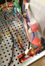
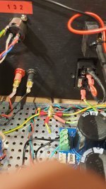
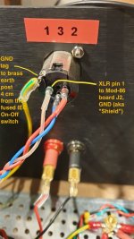
Following the advice I have received I have made numerous changes to the earthing or grounding so I now have 2 brass earth posts (bolts) protruding from the chassis floor.
Bolt # 1 is next to the Antec AS-4218 toroidal transformer (with shield) at the front of the chassis.
Bolt # 2 is about 4 cm away from the rear of the lowest tag on the IEC/Fused/On-Off switch.
- I used a spade crimped, soldered and covered with heat shrink.
B. Another wire runs to the Power-86 board, J1, GND (Pin 5).
C & D. Two wires run to each of the XLR connectors and these are soldered directly (because I don’t have
any spades small enough!)
- see photo
I have touched one probe of my DMM to the GND post of the IEC/Fused/On-Off switch and then touched the other probe all over the chassis and at J1, GND (Pin 5) and the XLR’s and got 0.5 to 0.6 ohm.
Following the advice I have received I have made numerous changes to the earthing or grounding so I now have 2 brass earth posts (bolts) protruding from the chassis floor.
Bolt # 1 is next to the Antec AS-4218 toroidal transformer (with shield) at the front of the chassis.
- the purple wire had to be lengthened slightly so I used 17 AWG Green & Yellow striped wire.
- see photo.
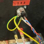
Bolt # 2 is about 4 cm away from the rear of the lowest tag on the IEC/Fused/On-Off switch.
- there are now 4 wires attached to this bolt.
- each wire is 17 AWG Green & Yellow striped.
- at the bolt end each wire has a ring crimped and soldered on.
- I used a spade crimped, soldered and covered with heat shrink.
B. Another wire runs to the Power-86 board, J1, GND (Pin 5).
C & D. Two wires run to each of the XLR connectors and these are soldered directly (because I don’t have
any spades small enough!)
- see photo
I have touched one probe of my DMM to the GND post of the IEC/Fused/On-Off switch and then touched the other probe all over the chassis and at J1, GND (Pin 5) and the XLR’s and got 0.5 to 0.6 ohm.
Attachments
I love to jump into a pretty much solved issue and add my „gossip“:
When I was researching „ground“, I foundthis very clear advice from several veterans and masters :
Make the security-ground (the connection from chassis to IEC) first and foremost, and secure it with its own bolt on the star-ground, so that it just can‘t be removed without purpose. Then you can add up any other ground-connection to that „tower“.
Heh. And then someone will bring up ground loops and we get to do it all again. ") Never mind that multiple ground points is not the same as a ground loop.
Never mind that multiple ground points is not the same as a ground loop.
Does your XLR connectors not have chassis tabs? Here's what I do:

The mains protective earth and Power-86 ground reference can be on the same bolt.
I think too many take grounding advice as absolutes. The only absolute I'm aware of is that the mains protective earth (PE) MUST connect to the chassis. Even that is only technically a MUST in electrical safety Class I devices, but I doubt most DIYers are able to build to electrical safety Class II where the protective earth can be omitted. So let's just say that the PE MUST connect to chassis.
All metal of the chassis, including metal controls that can be touched by the user should connect together and to the mains PE. That usually happens when you assemble the chassis, but it never hurts to double-check with an ohmmeter.
The Power-86 should connect to the chassis if you use RCA inputs. If you use XLR inputs the audio ground is referenced to the chassis through the connection at the XLR connector. It really doesn't matter how long the wire from the Power-86 to the chassis is, so you can use the same grounding point as the mains PE.
If the power transformer has an electrostatic shield it should (should, not MUST) connect to the chassis. You can leave it floating if you want. Then you just don't get the benefit of the shield. Ideally, the connection to the chassis should be short, so I would recommend using a separate grounding point for this. Again, that's a "should" not a "MUST".
This is the exact same advice I gave in Post #8. I'm a bit surprised that there's still confusion on this.
Tom
Never mind that multiple ground points is not the same as a ground loop.Does your XLR connectors not have chassis tabs? Here's what I do:
The mains protective earth and Power-86 ground reference can be on the same bolt.
I think too many take grounding advice as absolutes. The only absolute I'm aware of is that the mains protective earth (PE) MUST connect to the chassis. Even that is only technically a MUST in electrical safety Class I devices, but I doubt most DIYers are able to build to electrical safety Class II where the protective earth can be omitted. So let's just say that the PE MUST connect to chassis.
All metal of the chassis, including metal controls that can be touched by the user should connect together and to the mains PE. That usually happens when you assemble the chassis, but it never hurts to double-check with an ohmmeter.
The Power-86 should connect to the chassis if you use RCA inputs. If you use XLR inputs the audio ground is referenced to the chassis through the connection at the XLR connector. It really doesn't matter how long the wire from the Power-86 to the chassis is, so you can use the same grounding point as the mains PE.
If the power transformer has an electrostatic shield it should (should, not MUST) connect to the chassis. You can leave it floating if you want. Then you just don't get the benefit of the shield. Ideally, the connection to the chassis should be short, so I would recommend using a separate grounding point for this. Again, that's a "should" not a "MUST".
This is the exact same advice I gave in Post #8. I'm a bit surprised that there's still confusion on this.
Tom
Thanks for your reply which is as always very much appreciated. I am using XLR sockets rather than RCA sockets on the back panel of the chassis after reading page 7 of the Mod-86 Rev 3.0 Design Documentation. See photo. As far as I can see I have gone as far as I can on earthing/grounding everything.
My next question relates to a fuse for my Antec AS-4218 – which is a shielded version and the case for an Intelligent Soft Start.
Looking at the Antec website the AS-2222 is Power 200VA, Output Voltage 22V and Output Current 4.5 Amp.
Whereas the AS-4218 is Power 400VA, Output Voltage 18V and Output Current 11.1 Amp.
On page 18 of the Power-86 Design Documentation you say to use a fuse of 2.5 to 3.15 A slow blow for the AS-2222 when on 230VAC systems. I have Reduction Revolutions plug in power meter which shows I am getting 231VAC.
There are numerous “formulas” on the internet claiming to show what fuse to use eg. VA/VAC x 150% or VA/VAC x 300% etc.
eg. AS-2222 = 200VA/231VAC = 0.7 x 300% = 2.6 Amp fuse
AS-4218 = 400VA/231VAC = 1.73 x 300% = 5.2 Amp fuse
This leads me to page 17 of the Power-86 R3.0 Design Documentation where you recommend installing a soft start eg. your Intelligent Soft Start for transformers larger than 150-200VA. I suppose another option is to buy a Hammond 1182N22 2 X 22 VAC, 160 VA. The Hammond is cheaper than the ISS but the ISS may be the better option. I am not particularly ‘cost sensitive’ 😊. Appreciate your comments.
Attachments
You do want pin 1 of the XLR connected to the chassis. That's why it's shown with a filled solder dot in the design doc. The figure below is from page 32 (with annotation added).

You can keep the yellow/green wire if you wish but that tab is already connected to the chassis through the connector body. You do want to make the connection from XLR pin 1 to the chassis tab. XLR pin 1 also needs to connect to pin 1 of the input connector on the MOD86. I've shown the necessary connection in green in the image below.

Fusing is a pretty complex topic actually. If you do not use a soft start such as the ISS I recommend using a fuse rated for 2*VA/Vmains to 3*VA/Vmains. So a 200 VA transformer on 230 V should have a fuse rated for somewhere in the 2-3 A range. Round up. The point of this is to avoid nuisance blows, i.e., that the fuse blows due to the inrush current of the amp and not due to a failure within the amp.
A fuse rated for 2*VA/Vmains to 3*VA/Vmains is quite over-sized, which means that it won't protect as well in the event that there is a fault in the amp. So one advantage of using a soft start is that you can use a lower ampacity fuse. With a soft start, I'd size the fuse for 1.2*VA/Vmains.
In either case the fuse must be a slow-blow (time-delay) fuse to avoid nuisance blows.
Larger transformers draw higher inrush current, so for a larger transformer you may have to up the ampacity of the fuse even further than the 2*VA/Vmains to 3*VA/Vmains would indicate. At some point the ampacity of the fuse approaches that of the wiring in your house and simply upping the fuse rating is no longer desirable or safe. I'd say 200-300 VA is around where I start recommending a soft start. It's not a hard line etched in stone.
You can read my thoughts on soft start design and see measurements of the inrush current of typical toroidal power transformers here: https://neurochrome.com/pages/the-ultimate-guide-to-soft-start-design
In addition to the soft start feature, you may also enjoy many of the other features of the ISS, such as the low-voltage power on/off control, 12 V trigger, LED dimmers, etc.
Tom
You can keep the yellow/green wire if you wish but that tab is already connected to the chassis through the connector body. You do want to make the connection from XLR pin 1 to the chassis tab. XLR pin 1 also needs to connect to pin 1 of the input connector on the MOD86. I've shown the necessary connection in green in the image below.
Fusing is a pretty complex topic actually. If you do not use a soft start such as the ISS I recommend using a fuse rated for 2*VA/Vmains to 3*VA/Vmains. So a 200 VA transformer on 230 V should have a fuse rated for somewhere in the 2-3 A range. Round up. The point of this is to avoid nuisance blows, i.e., that the fuse blows due to the inrush current of the amp and not due to a failure within the amp.
A fuse rated for 2*VA/Vmains to 3*VA/Vmains is quite over-sized, which means that it won't protect as well in the event that there is a fault in the amp. So one advantage of using a soft start is that you can use a lower ampacity fuse. With a soft start, I'd size the fuse for 1.2*VA/Vmains.
In either case the fuse must be a slow-blow (time-delay) fuse to avoid nuisance blows.
Larger transformers draw higher inrush current, so for a larger transformer you may have to up the ampacity of the fuse even further than the 2*VA/Vmains to 3*VA/Vmains would indicate. At some point the ampacity of the fuse approaches that of the wiring in your house and simply upping the fuse rating is no longer desirable or safe. I'd say 200-300 VA is around where I start recommending a soft start. It's not a hard line etched in stone.
You can read my thoughts on soft start design and see measurements of the inrush current of typical toroidal power transformers here: https://neurochrome.com/pages/the-ultimate-guide-to-soft-start-design
In addition to the soft start feature, you may also enjoy many of the other features of the ISS, such as the low-voltage power on/off control, 12 V trigger, LED dimmers, etc.
Tom
1. XLR Pin 1 grounding
In “a month of Sundays” I would never have picked up that the small solid dot on the XLR wiring diagram had a different meaning than a small hollow dot, but now I do. Steep learning curve. I have soldered a short Green & Yellow striped 17 AWG wire between the XLR ground tag and the XLR Pin 1. See photo prior to applying heat shrink. I am not sure how to test that my soldering has been effective but I have tried 2 methods. Method 1 was to place one multi meter probe in the XLR socket Pin1 (ie. from the outside of the chassis) and with the other probe to touch A - the XLR metal body (ie. inside the chassis), B - the brass grounding bolt, C - the Mod-86 board J2 GND and D – the chassis; all measure about 1.0 ohm. Method 2 was to attach one multi meter probe to the male GND post of the IEC and then repeat A, B, C & D above; they all measured about 1.3 ohm.
2. Intelligent Soft Start – My cheque is in the mail!
Attachments
The "putting everything together" aspect is something I can cover better in the design doc. I'll need to think about how to best do that.1. XLR Pin 1 grounding
In “a month of Sundays” I would never have picked up that the small solid dot on the XLR wiring diagram had a different meaning than a small hollow dot, but now I do. Steep learning curve.
Perfect.they all measured about 1.3 ohm.
So I see. Thank you very much. Your order will be in the mail today.2. Intelligent Soft Start – My cheque is in the mail!
Thanks,
Tom
Hi Tom
Re: The "putting everything together" aspect is something I can cover better in the design doc. I'll need to think about how to best do that."
Would you welcome some suggestions on a system to help "put everything together"? I have developed a system that helps me as a person with very limited electronics knowledge to do do just that. Geoff
- Home
- Amplifiers
- Chip Amps
- Question regarding the proper way to ground the Modulus-86 amplifier