Hi.
I've built a pair of Icepower 200asc amps, and am using these in a biamplified system, with a DAC feeding an active crossover (RCA unbalanced outputl
The 200asc has a balanced input. Since I already have a pair of suitable transformers from another project (Jensen JT11-P1), I'm hoping to utilize these to converth the unbalanced input for use with the balanced amp (FYI, I am not interested in an active solution, nor passively tying one of the 3 pins to ground).
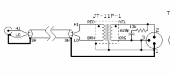
BTW, there are a Red and Brown lead going into the transformer and Black,White, Yellow and Orange leads coming out. I do not see any labels for them).
I see in the manufacturer's diagram (attached) that they show an RC network (13k/620pf) across the output leads attached to pins #2 and #3 (which is also tied to pin 1/screen, input shield).
Q:: Are all these connections and Res/Cap components shown in the diagram necessary and correct for my application?
I have seen other diagrams online that differ greatly, but noticed that Jensen refers to this one as "Best", which I interpret as only one way.
Thanks for any guidance in this effort.
I've built a pair of Icepower 200asc amps, and am using these in a biamplified system, with a DAC feeding an active crossover (RCA unbalanced outputl
The 200asc has a balanced input. Since I already have a pair of suitable transformers from another project (Jensen JT11-P1), I'm hoping to utilize these to converth the unbalanced input for use with the balanced amp (FYI, I am not interested in an active solution, nor passively tying one of the 3 pins to ground).
BTW, there are a Red and Brown lead going into the transformer and Black,White, Yellow and Orange leads coming out. I do not see any labels for them).
I see in the manufacturer's diagram (attached) that they show an RC network (13k/620pf) across the output leads attached to pins #2 and #3 (which is also tied to pin 1/screen, input shield).
Q:: Are all these connections and Res/Cap components shown in the diagram necessary and correct for my application?
I have seen other diagrams online that differ greatly, but noticed that Jensen refers to this one as "Best", which I interpret as only one way.
Thanks for any guidance in this effort.
Attachments
Are all these connections and Res/Cap components shown in the diagram necessary and correct for my application?
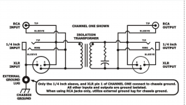
The same R/C arrangement is utilised in this commercial design: https://artproaudio.com/product/dti-dual-transformer-isolator/
Download the manual to see the schematic.
Hope that's useful.
T hak you for teplying.I added that to my file.
I reread Jensen's data sheet & it states that the RC "Damping network is necessary if the impedance of the unbalanced input is greater than 10K ohms, which is typical. Omit network only if input impedance is exactly 10K ohms"
Ice power specs for the 200 ASC state that the input impedance is 10K ohms, but it is 3pins (balanced).
The output impedance of my crossover circuit is 200ohms (unbalanced). I am using RCA cables containing twisted pair and shield connected at one end ( either source or load, as recommend)
Is it safe to assume that I can omit the damping network in this case since amp is 10k input Z?
Also, Can anyone explain why the output at pin 3 is tied directly topin 1, plus the xfrmr screen, the brown input lead, as well as the RCA cable shield?
Thanks again and Happy Holiday
The output is unbalanced.Also, Can anyone explain why the output at pin 3 is tied directly topin 1, plus the xfrmr screen, the brown input lead, as well as the RCA cable shield?
"Is it safe to assume that I can omit the damping network in this case since amp is 10k input Z?"
Yes
Yes
Is it safe to assume that I can omit the damping network in this case since amp is 10k input Z?
That looks to be a safe assumption yes.
Also, Can anyone explain why the output at pin 3 is tied directly topin 1, plus the xfrmr screen, the brown input lead, as well as the RCA cable shield?
To minimize any common-mode voltage. Not all input circuitry can handle a completely floating input source and most won't have enough CMRR to kill any hum if that scheme is used.
Rayman wrote: "The output is unbalanced." (?)
I thought the whole purpose of using the transformer here is to convert a 2-wire unbalanced input to 3-wire connection for the balanced (3pin) input of the Icepower 200asc("fully balanced") amplifier. I didn't want an unbalanced connection or I would have simply connected the amp directly by tying pin#3 to pin#1.The amplifier spec states it has a 3wire balanced input connection, plus I want also to isolate the connection from hum.
Because I seek to get a balanced output from the JT11-P1(if possible), what different wire connections should be made? (Scratching my head here).
Thanks for your help.
Omit the connection between the output XLR pin #3 and ground.
Remember that the XLR pin #1 is always connected to chassis ground.
If pin #3 is also connected to ground, you can't have a balanced output signal.
Remember that the XLR pin #1 is always connected to chassis ground.
If pin #3 is also connected to ground, you can't have a balanced output signal.
Rayma wrote: "Omit the connection between the output XLR pin #3 and ground."
Thanks for that instruction. I was negative worry that I couldn't get a 3pin balanced connection for the inputs of my balanced amp.
Looking again at the diagram Galu posted for the A.R.T. DTI unit, I see there is no direct connection back to the input, and the output is three discrete points.
So, if I'm notmistaken, in a similar configuration, inputs would be then red to "RCA 'tip", brown to "sleeve"(and possibly shield?), and the outputs are yellow to "High/+", orange to "Low/-", and chassis "gnd" would still be "pin 1/gnd"?
I'm still wondering about appropriate connection of black and/ or white leads(if used at all).
Am I missing something important here?
Thanks and enjoy your weekend.
Attachments
Because I seek to get a balanced output from the JT11-P1(if possible), what different wire connections should be made? (Scratching my head here).
I'm not sure its possible - normally to get a true balanced output you'd choose a trafo with a centre-tapped (CT) secondary. Rayma's suggestion might work though, it will depend on the input circuitry in your amp.
Thanks Abraxalito.
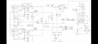
Anyone here familiar with the (ubiquitous) Icepower ASC power amp ircuitry? The only schematic diagram I found online is attached. From the number of other search results I was under the impression that I'm not the only one using these amps, nor this type of transformer!
Just trying to properly adapt an RCA input to connect to +/-/gnd inputs on these boards, not looking to "reinvent the wheel" 🙂
Again these fully balanced amps have a 10k ohm input impedance, so no R/C damping network should be necessary.
I hope someone has experience with this, please? Peace.
Attachments
Thanks anyway, but in my original post I stated that I am NOT interested in going to an active buffer. I merely asked for advice on using the transformers I have on hand (which were recommended for my application by the seller). My amps are completed, except for wiring these transformers properly.between RCA jack & amp.
I've now been able to determine that the black lead is from the transformer's "screen", and the white is tied to the can. Should either (or both) of these be used in my desired balanced output configuration, and if so, how should they be connected? I assume the can is physically grounded to chassis when mounted, but
What about the "screen" (black) lead?
Naturally, a schematic for balanced output use would be appreciated. So far all the schematics for the JT11-P1 I saw have been showing output connected to input, which I'm avoiding. Only the ART DTI schematic looks right (but I fear their transformer may have fewer leads or that they simplified the diagram for marketing purposes).
Before I solder anything, would the connections I noted in post#10 be appropriate for my amp, and should the amp's input ground lead be connected to rear panel(common), IEC "safety earth", or left unconnected?
Thanks for your patience in helping to sort this
I regard your connections as appropriate.
The way I read it is that the screen and can connect to pin 3 of your XLR and that no connection to safety earth is required.
RCA input and XLR output should be "ground isolated" is what the DTI blurb is saying.
rayma has greater expertise than I, so I hope he will return to confirm or deny.
The way I read it is that the screen and can connect to pin 3 of your XLR and that no connection to safety earth is required.
RCA input and XLR output should be "ground isolated" is what the DTI blurb is saying.
rayma has greater expertise than I, so I hope he will return to confirm or deny.

P.S. Your diagram shows pin 3 connected to pin 1. I believe these pins should not be connected, as the DTI diagram makes clear.
Last edited:
If what I last said is correct, then transformer screen and can should be connected to pin 1.
Doh! I knew I shouldn't have gotten into this! 😀
Doh! I knew I shouldn't have gotten into this! 😀
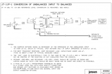
You can check the whole data sheet for JT-11P-1 there are schematics for unbalanced to balanced connections and adding transformers to electronically balanced circuits Thanks to parts express
Thanks guys
I looked at all the diagrams in the pdf on the Parts Express website. This is the only one specifically for unbalanced input; however it is still showing the white and black tied directly to the orange lead, which we decided against several posts up. It also shows the ground as a separate and defeatable leg connected to the chassis.
However...
Attachments
- Home
- Amplifiers
- Class D
- Use of transformer for unbalanced RCA to Icepower balanced input