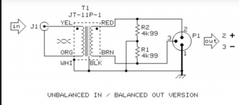
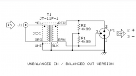
After extensive searching in Google images, I came across THIS schematic, which aI believe is THE ANSWER, using a voltage divider/splitter (two ~5k resistors) across the output and tying the center point to can/gnd & screen to get what appears to be an effectively balanced three lead loutput from the JT11-P1, being fed from a two wire unbalanced input: 😎
Any comments on this configuration? 🤔
Any comments on this configuration? 🤔
Attachments
Thanks Martha,
I didn't see your last post until after I posted my "discovery". We're on the same track (on two separate trains)!
🧠🧠
I didn't see your last post until after I posted my "discovery". We're on the same track (on two separate trains)!
🧠🧠
Worth noting is that the transformer has been "flipped"- now the red and brown are at the output, rather than input and the yellow & orange are now inputs and are physically separated from white & black leads.
Makes sense, as it's a 1:1 transformer...
🤔
Makes sense, as it's a 1:1 transformer...
🤔
Attachments
The latest configuration looks promising and doesn't conflict with the basic requirements I tried to convey earlier.
Should be ok.After extensive searching in Google images, I came across THIS schematic, which aI believe is THE ANSWER, using a voltage divider/splitter (two ~5k resistors) across the output and tying the center point to can/gnd & screen to get what appears to be an effectively balanced three lead loutput from the JT11-P1, being fed from a two wire unbalanced input:
Then-why-do-you-ask? 🙄I already have a pair of suitable transformers from another project (Jensen JT11-P1), I'm hoping to utilize these to converth the unbalanced input for use with the balanced amp (FYI, I am not interested in an active solution, nor passively
You already decided.
Respectfully, what I decided was not whether to, but HOW to use the transformers on-hand, that's why I ask (isn't that one of the purposes of the DIYAUDIO forum?) Some here DON'T know it all.Then-why-do-you-ask? 🙄
You already decided.
But thanks for caring enough to post! 😍

Thanks, Patrick, for asking a key question that ties in to my next question:So what is the input impedance of the Vin+ and Vin- nodes of the Icepower module ?
Patrick
The 200asc amp specs state that the input impedance is "10k ohms" and "balanced". Also the spec sheet for the JT11-P1 shows an RC "damping network, which can be omitted if
amp input impedance is10k ohms"
It occurred to me that this symbiotic matching of the transformer to my amp might be upset by the use of the two ~5k resistors in the diagram. Together, don't they put another 10k ohms in parallel with the amplifier's 10k input impedance reducing the load on the transformer outputs to 5k ohms? If so, how might this affect the system (i.e. frequency response, etc.), and could larger value resistors be used in that place?🤔
Thanks, once again, for advice.
With the centre tapped resistors the transformer secondary will be double terminated, seeing 5 k across it. Without them the secondary is still 'balanced to ground' by the amplifier input stage.The 200asc amp specs state that the input impedance is "10k ohms"
Thanks. 5k combined load-
Just what I was afraid of (I think that design assumes a much higher amplifier input impedance than 10k)!
Does the actual value of the twin resistors in the center-tapped voltage divider matter, other than being a matched pair?
If one were to substitute a pair of much larger value resistors (say, 100k ohms each) wouldn't the combined value (e.g. 200k) be "swamped" by the 10k ohms of the amplifier and therefore the combined load would still be close(r) to the 10k ohms "ideal"?
Wouldn't the circuit still work alright, or would that be a problem (and force me back to that "balanced to ground" hookup)? 🤔
"I gots to know!" 😊
Attachments

As rdf says and the DTI circuit confirms, this should work with or without the centre tapped resistor network.
You can experiment with those two scenarios and even with larger resistors. After all, that is the fun of diy! 😉
You can experiment with those two scenarios and even with larger resistors. After all, that is the fun of diy! 😉
Presumably the amp has a 'regular' active balanced input rather than a Hypex style floating instrumentation approach. If that's correct you can visualize the amp's input electronics as two normal unbalanced inputs each with resistors to ground, one input inverting and one not. In that case adding external resistors just parallels resistors already in the amp without in any way altering the circuit topology. In decades of studio work the wiring shown in your first post typically worked fine.
Whether tying the two equipment grounds together is necessary is gear specific. The grounds may already be interconnected via their power cords in which case I would try without first. The easiest way is to just heat shrink the drain wire and stuff it into the male XLR shell in case you need it later.
BTW, another option may be to just connect RCA hot to XLR pin 2, RCA ground to pin 1 and XLR pin 3 to XLR pin 1. I feed a Topping DX3 Pro+ into class D amp with balanced inputs based on the THAT chip using that arrangement.
Thank you for the advice. Original post covered the direct-wired option already, which doesn't really balance the input. But I do appreciate it's simplicity.
I'm most attracted to the balanced nature of Jensen's "center-tapped" symmetrical voltage divider and keeping the specified values with the resultant net impedance of 5kohms, would that tend to result in a frequency rolloff, and if so within the audio band of 20hz-20khz? (Again the amp has a specified input impedance of 10kohms).
Appreciate help in "dialing in" on a solution.🤓
...so close I can taste it...😛
BTW, Thanks to each and everyone who replied.
Sorry to dwell on the details so much- I'm just
SO excited to have completed construction of these amps, but lack the instrumentation to test out various ways of employing this "small" part.
I hoped your (collective) experience & insight might help me to choose wisely and also avoid unforseen problems.
Have a good week!
😎Okay. I think I figured it out. Did my homework, using Ohm's Law and RC filter theory.
With the specified 5k resistors for R1/R2 in the center-tapped voltage divider, and using my DSP unit (1Vrms max/10k output impedance) as the source, it would result in, worst-case, a signal voltage drop of 4.5dB, and a high frequency rolloff below 20kHz.
Changing R1/R2 to 50k ohms would give a net load of just over 9k ohms. The signal voltage drop is now closer to 3dB and the hf rolloff is pushed above 20kHz. Also, we can omit the damping network due to the load impedance.
Connecing the red & brown ransformer leads to my amp's "+" & "-" balanced inputs, respectively, then the black & white transformer leads to the center tap as well as audio ground. Done. (?)
Unless I may have missed something, by substituting the 50k resistors, I should be "good to go" (provided the 3dB signal loss is found to be acceptable).
I appreciate your assistance, all who contributed
😎
Attachments
10k source impedanse before the transformer? The Jensen spec says <600 ohm. Page 10With the specified 5k resistors for R1/R2 in the center-tapped voltage divider, and using my DSP unit (1Vrms max/10k output impedance) as the source, it would result
The DSP is very unlikely to have 10k output impedance. Which one is it?With the specified 5k resistors for R1/R2 in the center-tapped voltage divider, and using my DSP unit (1Vrms max/10k output impedance) as the source, it would result in, worst-case, a signal voltage drop of 4.5dB, and a high frequency rolloff below 20kHz.
- Home
- Amplifiers
- Class D
- Use of transformer for unbalanced RCA to Icepower balanced input