Denon DP-1200 (Remove motor/platter/bearing from old plinth to new)

Hello:

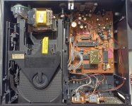
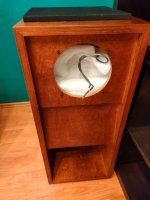
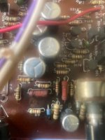
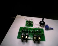
I have been staring at this for a couple days now, and figured I would try the experts before I ruin the motor. I have a Denon DP-1200, and want to use the motor/platter/bearing (without the tonearm) in a new plinth (with a new tonearm). The DP-1200 is a semi-automatic, so the motor won't run unless the on/off lever switch is on AND the tonearm has been moved away from the armrest. There is a circuit board KU-255B that controls the arm sensor.

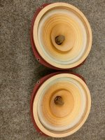
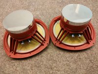
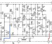
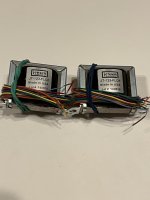
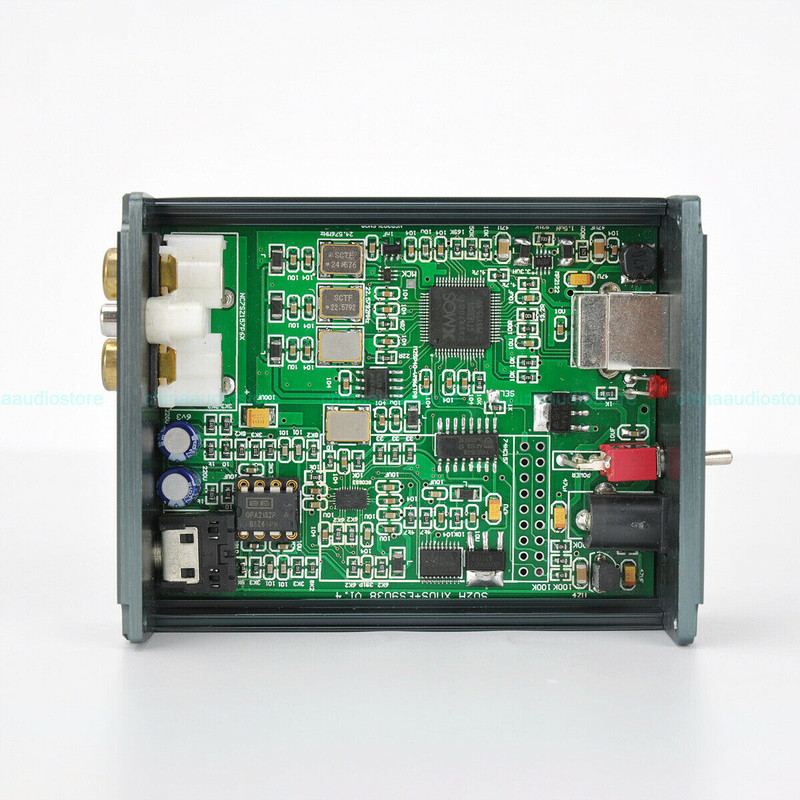
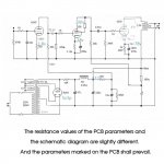
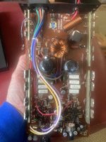
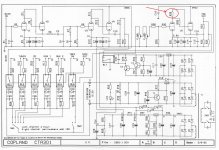
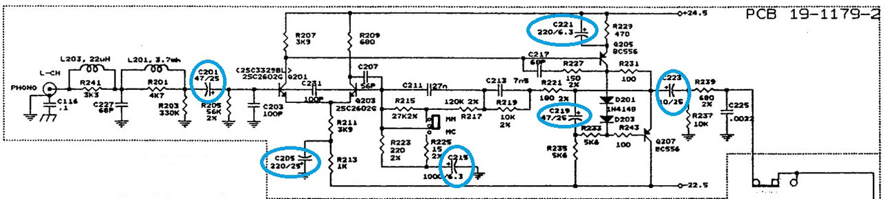
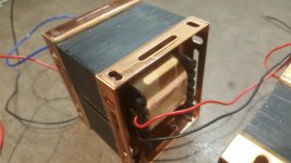
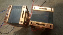
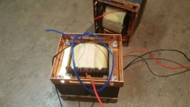
I am okay with soldering and staying safe while working on this; however, I cannot read a schematic to save my life! I have attached a PDF of the schematic as well as a photo of the motor and circuit boards). Three questions:

1. I believe I can take the two red wires currently attached to the on/off/standby switch and connect them to a DP-DT toggle switch and use that to turn the motor on and off. Am I correct in this?

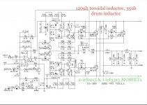
2. How do I remove the KU-255B circuit board (and all of its tonearm functions) from the circuit? There are four wires (W-13 (Orange), W-14 (Yellow), W-15 Gray and W-16 (Black) that run from the Servo Amp Unit KU-255A to KU-255B. If I just desolder those wires from the Servo Amp Unit, will the motor still run? (I'm wondering if the KU-255A board needs to sense voltage on one or more of those wires in order to provide power to the motor?) Is it possible to connect one or more of those terminals together on the KU-255A board so that it "thinks" the KU-255B board is there and telling it to provide power?

3. I am not sure whether any of W-13 (Orange), W-14 (Yellow), W-15 Gray and W-16 (Black) are ground wires (though based on its location on the KU-255A board, I believe W-16 (Black) is ground). If I remove the KU-255B board from the circuit, will this impact the ground of KU-255A (or anything else) in any way?

Thanks very much in advance for any help provided.

Attachments

  • page 19 (2).pdf
    page 19 (2).pdf
    467.3 KB · Views: 118
  • IMG_0792.jpg
    IMG_0792.jpg
    691.1 KB · Views: 232

PCB for Peak Voltage and Current detector

I have a few PCBs (shown in Photo) for the construction of a Peak Voltage and Current detector (shown in the other photo) as was presented in my article for Audioxpress (March 2015).
The device can be easily inserted between the amplifier and the loudspeaker and will measure the peak voltage and the peak current during the reproduction of a real music signal.
The price for the PCB is 25 Euros plus shipping.
Due to copyright, it is not possible to upload the article, but if you have read the article and interested, send me an e-mail at gntanavaras@gmail.com

Attachments

  • Peak detector PCB.jpg
    Peak detector PCB.jpg
    167.1 KB · Views: 599
  • The Peak detector device.jpg
    The Peak detector device.jpg
    353.4 KB · Views: 595

Rotel RA-840 DC voltage on one channel

Hi guys, I've got this immaculate Rotel ra-840 that looks very well cared for. There is not a single piece of fluff anywere inside! With no load I've got 11mv on one channel (regardless of source selected) and 2.4 (ish) volts on the other channel. One fuse on the combined pre/power board is blown. I'm seeing 21 volts on that (see pic) and 15mv on it's neighbour. There's 76volts coming from the supply board, does that sound right?
I built a chip amp some years ago but I've forgotten most of what I learnt. I have noticed a lot of the joints are dark grey as opposed to shiny but no components seem loose/wobbly. Any thoughts for a willing learner?
Fuse highlight diag.png
Screenshot (86).png
Screenshot (87).png

Triggering my PA amp

Hi
I used to use a one click extension lead to power on my hidden pa amp for my subwoofers
My av amp used to be plugged into the main socket so when that was turned on it used to power the other sockets to my pa amp

I’ve now switched to a minidsp pre amp this will not power the other sockets on when it’s turned on presumably because it has a 12v power supply

Anyone have a work around I can use to power up a av amp using something with a 12v power supply

Thanks

Bouyer As240 revisited for a new life

hello to all, here I have at my disposal 4 Bouyer type AS240 and 245 amplifiers which are intended to work mainly under 100V line, their design had been made for this but they can also be used under 4 - 8 or 16 ohms thanks to its output transformer.I used about ten years ago it's amplifiers for car races or noises and quite important with as loudspeaker 100V line horn type IT-50 from Monacor. as the power of this amplifier is 240W rms at 480 W peak,and the number of speakers that I had to place was too large, I turned to QSC type ISA800T amplifiers which are dual mono but with more power available for less weight: 2 bouyez are 52 KG for 2 x 240W, the QSC isa800TI weighs 26 KG for 2 x 800 Watts knowing that the power to be used must be 68% for the 100V line.
to get to the heart of the matter, I would like to be able to use the 4 output transformers whose primary impedance is 2 ohms defined on the Bouyer plan, so I'm looking to make an amplifier with 4 x 100v line output and an SMPS power supply preferably to maintain a reasonable weight and therefore I am looking for an amplifier under 2 ohm load not too complicated to make or so as on sale on aliexpress in this style:
https://fr.aliexpress.com/item/4000....0.0.2175378dBIRjDi&mp=1&gatewayAdapt=glo2fra
https://fr.aliexpress.com/item/1005....0.0.2175378dBIRjDi&mp=1&gatewayAdapt=glo2fra
SMPS:
https://fr.aliexpress.com/item/4000....0.0.2175378dBIRjDi&mp=1&gatewayAdapt=glo2fra

in summary: a common power supply with 2 stereo modules or 4 mono modules, I only plan one potentiometer per channel as well as their individual power switch and for their signal inputs it will be by mixer which will have all these preamp functions and tone corrector. only thing that seems important to me and to have 4 VUmeter output to keep an eye on their output level.
I have no feedback from these amplifier boards. ( original schema As240 -245 with 12 x 2n3055 transistors output )

Phil
BOUYER AS245a.jpg

USB PC oscilloscope. Dual channel. 18 mega samples/s

Dual channel PC USB oscilloscope.
18 mega samples. Up to about 1MHz bandwidth so ok for audio work or low frequency digital work.
Analogue display and spectrum analyser display.
Trigger is none, positive and negative.
AC/DC switches.
Data logger mode for saving a stream of captures to a pc file.
Print out screens.
Comes with USB scope interface and CDROM and instruction sheet.
Requires x10/x100 scope probe. Not supplied.
£30 including p+p to UK only.


1600.jpg

Ideas on old preamp repair

I recently shipped an ancient Threshold FET 10/pc preamp to my son. It was working last time I used it but one channel was DOA when it arrived. I have the unit back and am contemplating a repair strategy. Given that the unit is at least 30 years old I'm thinking beyond just hunting down a bad semiconductor or whatever. Bad solder joint from rough shipping? A bad electrolytic? Combination of things or cascade of failures? Regardless, I want to get it fixed for another 30 years.

Thus far I have located the point on the board where the input signal goes dead. Power supply works fine and no sign or anything burnt. So, what I have in mind is:
  1. recap everything and reflow all the joints on the board on principal (eliminate those potential sources of failure and reduce liklihood of future failure)
  2. diagnose what's actually blown and replace accordingly if the above doesn't fix it.
Is this a reasonable strategy or am I just making work for myself? I haven't found have a schematic or any other tech info that might help. I'd call myself maybe an intermediate hobbyist at this stuff (worked in stereo repair shop ages ago, have simple bench setup of a scope, AC voltmeter and signal generator). Comments and ideas would be very welcome. Thanks,

Technics SU-A900Mk2

New on this forum!

I have a full Technics stack (bought in 1999) and has worked perfectly fine for years, however, I now seem to have a problem with the phono.

All the rest (CD, MD, Tuner, Aux etc) all work fine, but have a static hum when amp is set to phono even if the deck is not powered on and the banana leads are disconnected.

This seems to point to the phono stage internals.

Is this something the could be repaired? If so, any idea how much would that cost (am in UK)?

Or is it worth me buying a used serviced model from a reputable dealer or P/Xing the existing one for a replacement?

thanks
David

Martin Logan CLS2 Electrostatic Speakers

Hey all,

Have to continue unloading some collected Gear...

A Pair of Martin Logan CLS2 Electrostatic Speakers with Oak (?) Frames in very good condition. The panels have no noise issues and have no stator separation, and are clear of any crud on diaphragm.

Interfaces appear to have the caps upgraded to PP caps (by previous owner).

Pick up only for now in West Sub of Chicago....Audition advised to confirm proper operation.

How's $1350 for these classic speakers?

Attachments

  • 00b0b_8EKJFAUYX4Zz_0CI0lM_1200x900.jpg
    00b0b_8EKJFAUYX4Zz_0CI0lM_1200x900.jpg
    98.3 KB · Views: 128

Unity gain buffer

Hi there...
for driving pair not so usual amplifier for my open baffle speakers I need some transparent unity gain buffer stage that will supply audio signal to my amps. Buffer stage must have low output impedance in order 50…200 ohms. My preference is all discrete technology, without IC. My amplification setup have 2x24Vdc and 30Vac sources (and any derivate from this voltage is possible). So, any recomendations for that type of buffer stage?

Thank you all for helping me on this and given ideas..Dubravko from Croatia

Thoughts on Vinyl Mastering

They were expected to do this with media which didn't allow for this ( vinyl). With digital media there is no issue letting low end phase issues and customers don't ask for it to be monoed, then... responsability is now on producer/ recording-mixing engineer/artist.
The (vinyl) recording engineers were expected to do this, just like I was expected to clean my room when I was a teenager. Sometimes it did actually happen.

X100 backengineered here

X100 backengineered

X100.GIF


I am very interested in feedback on this design (which is based on patents held by http://www.passlabs.com and thus not available for anything but research). To scale power, simply change rail voltages (and increase value of feedback resistor to get enough front-end voltage gain to drive outputs to saturation). To change level of Class A drive, increase bias resistors. To improve "supersymmetry" and reduce gain, increase value of resistor between bottom of input FET's.

The 1M resistors are there for simulation purposes and would ordinarily be smaller. And yes, I simulated this design using a Spice CAD package.

We are probably looking at something very close to a commercial X-series amp (without embellishment). If you like feedback, place the feedback loop around the output transistors.


[Edited by Petter on 02-21-2001 at 07:52 AM]

Marantz CD273

Don't think ive ever posted here before but have read the board for quite some time.

So first of all hello,

I've got a few CD Players but the one I use most is a CD273, mainly because I like the Size and it plays well.

Is anything worth changing, Any recommendations?
Op amps already able to be swapped and most caps have been changed due to its age, But any worthy gains that can be achieved?.

Many thanks.

Attachments

  • cd273.jpg
    cd273.jpg
    991.8 KB · Views: 719

What sort of power can a vintage 12" speaker produce, at the very least?

I have a 70's guitar combo amp which I use with my basses - an FBT Jumbo 100. I bought it thinking it's a 100W unit, especially because it's kind of enormous. Turns out, it's a 10W amp. When I open it, I see it has a 12" speaker.. I'm planning to replace the PSU and amp circuitry in it, so I can get about 30W out of this. However, should I keep the speaker? The text on the speaker doesn't give any hint on what is its power. rating. All I could find online is that it's an old Philips unit, and that it has a nominal impedance of 4 ohm, which I could confirm myself, but no firm info on power.
So the question is: what is the lowest power 12" cabinet speaker's power output? I would be surprised if it were only 10W.
FBT_Jumbo_100_speaker.jpg

Flat Wall Mount Stereo MLTL using TC9Fs (2)

This thread is being started as an OT discussion from the Tabaq thread. The design is a compact flat wall mountable stereo speaker that has great midrange clarity and pretty decent bass extension due to the mass loaded transmission line (MLTL) approach that was added to the original design based on this thread. The original open-ended TL design looked like this:
2011-05-26170029_74434.png


I modified the dimensions of that design to fit two speakers on a single panel of 20in x 30in foam core board. The revised design plan is as follows (added 1.0in x 2.2in x 2.44in long vents):

334670d1362710759-foam-core-board-speaker-enclosures-p1040134.jpg


Here are some photos of what it looks like:

334668d1362710759-foam-core-board-speaker-enclosures-p1040132.jpg


Close up of the constrictor vent:

334669d1362710759-foam-core-board-speaker-enclosures-p1040133.jpg


If you want, you can decorate with a picture frame (the craft stores have a ready-made 20in x 30in frames in stock) and a poster or picture to look like this (this one has a built in class D amp and BlueTooth connectivity in addition to 3.5mm stereo jack):

496443d1438359290-flat-wall-mount-stereo-mltl-using-tc9fds-wall-mltl-framed.jpg


Several people have built this with good success. Some have split it off to be a single (non-stereo) speaker.

Here is a sound clip:
diyAudio

Here are measurements of the vent bass output:

334671d1362710759-foam-core-board-speaker-enclosures-flat-mltl-freq-resp.png


Here are more recent measurements from a meter away with speaker mounted on wall at 53in driver height from floor. The wall and room combine to extend the bass to a very deep 30Hz, albeit lower amplitude (but still very present). The drop off below 100Hz is due partly to room modes and also just fall off with distance:

496448d1438360794-flat-wall-mount-stereo-mltl-using-tc9fds-flat-mltl-fr-1m-53in.png


The impulse and step response are quite nice:

496449d1438360794-flat-wall-mount-stereo-mltl-using-tc9fds-flat-mltl-ir-1m-53in.png

Please advise! I want to fix my parents AudioLab sound system.

Please help!

My parents have an AudioLab 8000p and 8000c separate pre and power amp.

The system served them well for many years but a while ago a fuse went on the house fuse board. The speaker let out a massive bang and the pre/power amp stopped working, despite the fact they were meant to have overload protection.

They were originally very expensive so they seem worth repairing, but at the same time I don't want to spend lots of money to be told it's not repairable etc.

I would love to fix this for them but have no idea where to start as I don't know much. Any advice would be much appreciated!

Thank you!

How much Watt if using MJE15030/31 as output in power amplifier?

MJE 15030/31 data TO-220:
Continuous current: 8 A
Peaak current: 16 A
Total dissipation: 50 Watt
Max temp: 150 Degrees C
Rjc: 2.5 C/W

Where is the Watt limit, would you say, when using MJE15030/31 as output devices?
Is there some good option to use when choose TO-220 devices?

I also have considered MJE3055T/2955T. 10 A and 75 Watt. 1.67 C/W.

XSIM scheme + filter response of KEF Reference Model Three

Hello Gents,

Kinda started with crossovers about a week ago so pretty noob to begin with. Studied Allens famous article of course and some online tutorials. I know what capacitors, Inductors and resistors do and understand the math that comes with it but I'm fairly new to audio in general.
Picked up a couple of Kef Reference Model Three's recently and although they sound majestic to my ears I also use them to learn more about crossovers. I've got the actual scheme + vlaues from this forum and started playing with XSIM. I don't have the specific drivers specifications. The only thing I have is:

Frequency Response: 40Hz to 20kHz
Recommended Amplifier: 50 to 300W
Crossover Frequency: 140, 400, 3000Hz
Impedance: 4Ω
Sensitivity: 91dB
Bass: 2 x 200mm B200 pulp cone
Midbass: 1 x 160mm B160 polypropylene cone
Midrange: 1 x 160mm MB160 polypropylene cone
Tweeter: 1 x 25mm NT25 soft dome

Here is the basic scheme and the filter responses. Now the question is whether or not there's room for improvement or does that all come to presonal preferences mainly?
Note: I'm going to replace the bipolar caps and resistor from Bennic with better ones so it might be a good idea to each some values here and there as well.

Comments much appreciated...

regards

Willem

filter-response.png
scheme.PNG

Silly Wok-Fi build. It works!

PiePan1.jpg


If you have never heard of Wok-Fi it’s the practice of building Wi-Fi extender antennas from Asian cookware, sieves and the like.

Out in the barn there is a seismometer that needs Internet access to upload data. Rather than run a lot of CAT5 underground it’s linked with a Wi-Fi extender to the house network. Easy. But out there it’s at the edge of its range and likes to complain that it is "too far from the router."

So I kludged up this monstrosity. Just two aluminum pie pans glued together. Not parabolic at all, and it even won’t focus light. I poked the antennas through the back side and pointed it at the house.
PiePan2.jpg


It works! It gives me 12dB gain on average. Can’t quite believe it. Perhaps there will be a more elegant solution in the future, but for the moment I’m happy.

Help needed: IT hum

Hi, I have a pair of interstage transformers in my monoblocks. One of the ITs has a mechanical hum (audible from the listening position and a real PIA) and the other does not hum. The ITs seem to perform the same, other than the pesky mechanical hum. BTW: No hum from either speaker, so its no in the signal. Any thoughts on where to begin to debug this? Thanks, Pat

I'm trying to understand how DAC chips work

Hello .
Please forgive my ignorance, but I would like to understand how a multibit DAC behaves when it receives information from a delta-sigma DAC. This is the case when using a converter (with DAC delta-sigma inside) from usb to s-pdif..
Is it possible for a multibit chip dac to behave like a transparent system, i.e. to bring a minor change in the sound if there is another delta-sigma type chip in front of it? And here I mean the conversion, for example, from s-pdif to usb followed by the multibil dac. That is, if the delta-sigma DAC sequentially transmits bits of information, maybe that the multibit DAC will take information fragments and it will pass them on "slices" of delta-sigma type information. That is (just as an example) if delta sigma sends 4 bits of information to the multibit dac, the latter will practically try to process all those 4 bits of information and not maybe 16 (depends on chip) as much as it can, because that's what was transmitted to it.

I'm waiting for you to tell me where I'm wrong.

FS: Coral Beta 8 speakers

I am selling my pair of perfectly working and sounding Coral Beta 8 speakers. 7,5 ohm impedance for both speakers.
The grey dots on the cones are the usual ones from age and dust, but it doesn't alter the sound at all.

I can also provide them in professionally made cabinets.
Price with cabinets EUR 1.150 plus shipping
Price for speakers only: EUR 850 plus shipping

Reasonable offers are welcome.

I can organise door-to-door shipping of the speakers in cabinets within Europe.
Speakers only shipping is possible Worldwide.

Attachments

  • IMG20220308133853.jpg
    IMG20220308133853.jpg
    155.6 KB · Views: 505
  • IMG20220308133914.jpg
    IMG20220308133914.jpg
    319.8 KB · Views: 386
  • IMG20220308133917.jpg
    IMG20220308133917.jpg
    232.9 KB · Views: 411
  • IMG20220308133919.jpg
    IMG20220308133919.jpg
    235.3 KB · Views: 343
  • IMG20220308133938.jpg
    IMG20220308133938.jpg
    268.2 KB · Views: 317
  • IMG20220308133949.jpg
    IMG20220308133949.jpg
    310.3 KB · Views: 309
  • IMG20220308134008.jpg
    IMG20220308134008.jpg
    258.8 KB · Views: 385
  • IMG20220308134140.jpg
    IMG20220308134140.jpg
    83 KB · Views: 406

  • Article Article
I/V stages and noise

I/V stages have been a passion for me for a rather large number of years but only very recently have I approached I/V stage design from the point of view of getting the lowest possible noise. In the past so long as my estimate of the I/V noise was 6dB or more below the best recording noisefloor (say -92dB on 16bit material) then I considered job done. Now though my curiosity has been awakened for pursuit of 'how low can I go?' in relation to I/V stage noise.

The first port of call in an I/V stage has always been an opamp in transimpedance mode. Indeed lots of DAC chips are purpose designed for this kind of I/V and even many have on-chip opamps to facilitate this application. The best opamp I/V I've heard to date was from AD811. So I opened LTSpice and downloaded the AD811 spice model from Analog Devices, pasted it in and I figured I was all set to admire AD811's impeccable noise performance as I/V stage.

But it turns out the rabbit hole goes a bit deeper. Setting the I/V resistor to 600R (as AD811 DS recommends for -1 gain) I got an almost perfectly flat response over the audio bandwidth of 5.3nV/rtHz. That's a noise density figure, to get the full audio band noise, multiply by 141.4 (which is the square root of 20,000). Answer = 0.75uVRMS. To get the SNR plug in the signal level - the DAC is PCM56 with +/-1mA output so the signal is 1.2V p-p or 424mV. Crunch the math and out pops an astoundingly good result of 115dB SNR, even ignoring that the output signal needs gain to bring it up to the 2V standard CD level. But I was suspicious of this as based on my experience of modelling CFB amps on paper, they're kinda noisy and 115dB isn't at all noisy, especially with a flat line down to 20Hz where normally noise would be rising due to 1/f.

So I needed some kind of sanity check for this result. I figured I'd find the lowest noise LT CFB opamp (which require no download of subckts, the LT parts are built in to my LTSpice) and do a comparison. The LT part I settled on is LT1227 - its a bit noisier than AD811 (3.2nV vs 1.9nV on voltage and 32pA vs 20pA on current) but close enough for a sanity check. And the result was interesting : 21nV/rtHz at 1kHz and rising reassuringly below that frequency. A huge difference that could not be accounted for by the DS noise difference. That's 12dB worse and just 103dB SNR if we ignore that the density figure more than doubles by 20Hz.

I'm no expert in deciphering Spice subckts but I decided to have a look to see if the AD811 subckt models the noise. Since I have no idea what to look for I opted to compare with the subckt I downloaded for AD797. I reasoned that because low noise was AD797's big selling point they'd be bound to include that in the model. And sure enough, in AD797's subckt there are helpful comments which show the part of the circuit which sets the noise parameters. There are models (DIN,DEN) which are referred to right at the bottom. I'm guessing they're diodes. Any subckt without these won't model noise and sure enough, AD811 lacks them. As does AD844 which I also tried. Since I already had the subckt for it, I wondered - how does AD797 fare as I/V ? (You need to remove the decompensation node in the definition to make it compatible with a standard 5 pin opamp).

AD797 turns in a very impressive 14.3nV/rtHz figure (using 2.8k feedback resistor) giving an SNR of 120dB. LT's competitor LT1115 fell a fraction of a dB short of the AD797, at 15.1nV/rtHz but LT1128 beat it out by about 1dB, at 13.1nV/rtHz. LT1028 gives the same result as LT1115. Oddly, the 1128 only differs from 1028 by virtue of its compensation, the IPS (and hence noise) should be the same. So the last dB of performance seems an area of uncertainty, but clearly CFB opamps aren't the winners in the SNR stakes.

Going back to good old fashioned pencil and paper, how does AD811 do? Its crucial noise parameter is the inverting input current noise which sees 600//1200 (the latter inside the DAC) so 400R. 20pA * 400ohm gives 1.1uV in 20kHz. The +ve input noise at 1.9nV gives 269nV. The noise gain is 1+600/1200 = 1.5 so I'm getting 1.7uV with 424mV output or 108dB SNR. This excluding the intrinsic noise of the resistors themselves so the real result will be slightly poorer. Rather than do that math, I'll estimate back from the LT1227 result : as -ve input current noise dominates and that's 4dB poorer on LT1227 than AD811, I figure the AD811 result with resistors will be 4dB better than with the LT1227, i.e. 107dB.

I'll go on to talk discrete I/V in a later post.

Setting gain on a vintage Marantz 33

Last year I restored a vintage Marantz 33 preamp. Unit sounds nothing short of amazing, but it has a small problem… 20db of gain. Sources these days usually have a 2V output (mine anyway), so I usually need unity gain.

My last work on the unit was replacing the volume slider (old one was shot and injected a lot of noise, plus a huge channel imbalance due to mechanical failings), and slow trying to reduce gain, by increasing R134 from 1k3 to 2k7 (see attached schematic - blue is input, red is output). This halved gain (measured on my scope), but didn’t help me get a better range on using the volume slider at all (I suspect the old one was attenuating more than it should so it inadvertently helped).

I’m thinking about lowering the gain even further. I should reach 2x if I increase R134 to 15k, if I understand the schematic correctly (1+R135/R134), but I’m not sure that’s the way to go. Should I also decrease R135? (maybe go with 7k5 for both). I have to admit I don’t fully understand how current affects this and if changing the “feedback” also impacts its frequency response/linearity.

Any advice is much appreciated.

Attachments

  • Screenshot 2022-12-26 at 12.41.35.png
    Screenshot 2022-12-26 at 12.41.35.png
    152.1 KB · Views: 104

convert a ported sub into a horn

I’ve been reading various accounts of people using various tuba/wrecker type horns to great effect in their home theatres. I would like to build something similar but due to where I’m located the cost of importing all the gear is prohibitively expensive. I have a 12inch ported sub made by wharfedale- powercube 12 150w-kicking around- could I utilise the driver and amp in a horn/tl build and expect to get results better than what it already produces? Is it worth exploring further?

review of sub-http://www.audioreview.com/product/speakers/subwoofers/wharfedale/powercube-12-150-watt-powered-subwoofer.html

Similar/equivalent replacement mosfets for IRF6215 & IRF3315

Hi, I’m looking for some replacement mosfets for a couple discontinued ones. The only identical ones I’m finding are either stupid expensive, or I can’t be sure if they are not just garbage knockoffs. The part numbers are IRF3315 and IRF6215. This is for a subwoofer plate amplifier repair. Any help would be sincerely appreciated. Please see circuit diagram I’ve included if that helps. Thanks!!!

Attachments

  • 9C077C34-E466-44F3-854F-D43F7B8FAC5D.jpeg
    9C077C34-E466-44F3-854F-D43F7B8FAC5D.jpeg
    115 KB · Views: 237

Fisher KX-200 Bias circuit problem

Hi All.
I am working on a Fisher KX-200 with 7591 outputs.
These are a u-build "Strata Kit" which have a built in bias meter.
They are biased for original tubes at -16VDC which I have read is not great for tube life.
So.. the solution (I read) is to change the 390 ohm resistor to 240 ohm which will allow you to use the meter
to bias to a better value for tube life.(mine came out to -19Vdc 450V on plates with this mod.
I also replaced the 1000 ufd (35Wvdc) can in the neg bias circuit with new 65V WVDC electrolytics as original was leaking goo.
The big issue I am having however is the 15 ohm 5W resistor between the pins of the
1000 ufd cap is getting super hot and smoking after only a few minutes.
It did not do this before.
The volts on the cap are around -32v and (-25 on other side of resistor) so it seems to be dropping about 7volts across the resistor
which is 433mA by ohms law which would seem to only be about 3 Watts across
The resistor Which should be ok for a 5 Watt power resistor.
I am unsure wether I did something wrong or
this is a result of bias change and I need to increase wattage of this resistor.
I did observe polarity on caps with positive going to ground as this is a negative supply.
Any thoughts?

Kicad "empty DIP socket" symbol ?

Driving me nuts.....
I've been searching a lot, but for some reason I cannot find a "symbol" for empty DIP sockets.

I am brand new to this software, and I have a feeling it is simple.....I just can't find out how to do it, or where to find it.


Smaller DETAILS................
I'm reverse-engineering a circuit board, and there are two sockets on the board.
One.....is a standard 16pin DIP that has a removable ribbon cable to an off-board rotary switch.
Other....is an 8pin DIP, possibly for a user-replaceable filter circuit.

I'm not going to get PCB's made....I am just trying map-out the circuit in order to visualize, and try to understand what's going on.
(This relates to THIS THREAD....... ) and pics are there.

Buying directly from Texas Instruments

Since there are some threads about Mouser and Newark and I didn't want to go off
topic in the "OPA1656 " thread where it didn't get much reaction , here are some
thoughts about buying directly from manufacturers instead of distributors , in this
case Texas Instruments.

There must be a lot of rich , mainly Canadians and Americans , on this forum
because I've never seen a mention about buying directly from TI and saving some
money
doing so. ( of course I haven't read that much of the 1000's of threads
here). So for us less fortunate 😱: Have you seen the price differences between
Mouser/Newark/Digikey/RS/Farnell,... and the T.I store ?
😱 If you're buying the more expensive opamps and other audio related parts , this really starts to add up ! Even on the cheaper ones . (sure you'll find some where the difference is not that much). Maybe not many on an audio forum are into logic like 74HC/AHC/LVC,...but I am and even on those cheap(er) parts , prices are much lower. Don't talk to me about margins , TI has to do the same to get it to you.
So why not buy directly from the cheaper manufacturer , you know , the company
who actually makes them
over Warren Buffett's orderpickers/robots ( and B. Gates apparently Access to this page has been denied. , I'm not getting political here) . mouser.com/BerkshireVisit/
For all the parts I have researched , TI sells them even for 1 piece . Huh, what ?
Imagine me buying one 74LVC1G32 in SOT23 for 0,066 $ ? 🙄

Could it be the extra shipping costs ? As far as I know TI doesn't sell R's , C's ,..
and all other parts that distributors do . But I see many on here already buying from
more than 1 source . Sure some give free shipping above a certain amount , but
even then , shouldn't I prefer to buy directy from the TI store ? 🙂
TI does ask for a company name and it's URL when you buy as non registered buyer , but that is easily circumvented by "bending the truth" a little. 😛 I don't see them checking. I haven't registered yet to see how that goes.

So what are your experiences buying directly from the TI store ? Any pitfalls ? How is shipping/delivery ? Any reason not to buy from them ?

Good idea? Sorbothane in tweeter surround in highly braced cabinet

I am designing a two way bookshelf speaker with quality drivers and want to do my best to do them justice.
Woofers benefit from highly braced, inert cabinets to raise the frequency of the cabinet wall resonances above their operational range. The reverse is true for tweeters; a sloppier cabinet wall will resonate below the frequency range of a tweeter producing good results.

Do you think a think a thin layer of sorbothane under the tweeter flange would help solve the issue the issue of mounting a tweeter into a very braced/inert cabinet that may have higher frequency wall resonances? If so what duro would be ideal?

Compensation in ESP P101

HAPPY NEW YEAR fellow builders!

Quite a few threads on DIYAudio have discussed this amplifier designed by Rod Elliott (Project 101 at sound-au.com). Yet, I have not seen much of any performance measurements of finished implementations. It occurred to me that I could share some of mine after having experimented with feedback compensation in my build. After all, I have to give credit to great minds here who showed and explained their designs.

A disclaimer is due before I move on: my daily job has nothing to do with EE, I am just a curious constructor, and this is my first class-AB amp. So, I make no pretense of TRULY knowing what I am doing.
. . .
While waiting for the PCBs from ESP I spent a good while at a simulator. The simulator did provide for a very stable amp with complex loads however THD at higher frequencies gave me some hesitation. While THD-1kHz was below 0.01% on simulator within the whole power range, the THD-20kHz was rising quickly with output to well over 0.5% way before clipping. The 10 kHz square wave output looked too "triangular" on simulator, and I had noticed the same shape in a scoped output waveform of a real build by a member here. The slew rate on simulator was barely reaching 5V/us. Theoretically, this should be good enough for my low power implementation (25W into 8R, both channels driven). But wait, Rod had mentioned in his description that SR is 15 V/us and that it can easily be increased... I got curious.

It might have been a neophyte's blunder with the sim, but where? There are too few components in the design that could be considered suspect of performance limitation. I began tinkering with feedback compensation and will try to show what I did whilst keeping compliant with Rod's explicit rule not to disclose circuit component values not revealed in the public page of the project. If you have the boards purchased from ESP then you have access to complete information.

Plain reduction of the Miller cap C3 around VAS Q7 in P101 default version (see my circuit fragment doodles below) predictably led to improved THD but also deteriorated stability - a scary area for me where I did not want much compromises. How do I reduce the C3 and yet maintain acceptable stability margins? Long story short, I ended up building first a modification which I denote as "Version A", measured it, then tinkered on and finished up with "Version B". Both turned out to be working well, reducing THD notably compared to the simulated default arrangement. Version B, as far as I understand, can be considered as a variation of TMC. Please correct me if I am wrong. I derived it from the multiple elaborate compensation ideas used in other amps and discussed in SS threads. A definitive overkill for this amp but a good cure for curiosity. I had also trimmed some component values and set LTP tail current in Version A at ~1.7mA, and in Version B at ~2.8mA. It was an important step but had much less impact on THD improvement compared to the compensation circuitry. Everything is inter-related, though.

Picture below shows the three compensation schemes and corresponding loop gain graphs with stability margins (simulated) - the Project default, the Version A and the Version B:
Comp.circ+LG.png


Here is the scoped square wave response for versions A and B with 8R resistive load and with 100nF in parallel with 8R. In neither case an output inductor was used. Visually, the difference between the versions is insignificant and the ringing in case of 100nF||8R load is in my opinion acceptably contained in both versions. In my final build I did include small output L||R cells just to play it safe.
Square w1.png

In absence of sufficiently fast square wave generator I could not reliably measure SR, but the ones predicted by the simulator were 32V/us for ver.A and 28V/us for ver.B.

Next comes comparison of THD measurements I took at different frequencies and output levels:
THDvsP_summary.png

While there is little difference in THD at 1kHz between A and B (could be within measurement error), higher frequencies do reveal discernible advantages of version B at powers above a couple of watts. Interestingly, THD value of ver.B has some minimum at about 5W output while ver.A has it at around 1W. I have not figured out yet the mechanisms behind this behavior. As well, my measurement rig is quite simple and I am learning yet, so results may not be reliable in absolute terms but were good enough to spot the differences and ballpark the achievable THD levels. THD of ver.B at frequencies above 5kHz is probably somewhat lower as the shown results are bordering with soundcard's capabilities.

When it comes to distortion spectrum components, it looks like ver.B does a better job in suppressing higher order ones starting from the 5th at higher frequencies. The 1 kHz is peculiar though (with suppressed 2nd and 4th as well), but THD is overall low so I did not concern to investigate. The green dotted line in the plots below is added at -100dBc for easier comparison. Also note how the noise shaping of my sound card alters the graph when run at sample rates of 96kHz and 192kHz for measurement above 5kHz. As well, you can see the very unfortunate pick-up of SMPS radiation just below 80kHz due to its proximity to the measured channel in my (too) small enclosure. The other channel suffers from this garbage much less due to being located some ~30mm further away from the culprit than the shown channel... One of my real blunders (aka lessons).
THD.png


Two tone IMD (19+20 kHZ) also confirmed notable improvement (about twice lower) in ver.B compared to ver.A. Here is ver.B measurement at 25W output:
IMD_CCIF_25W.png


. . .
So, did I find the answer to the catch of SR differences between those stated by the designer and those I saw in the simulator? Most probably not. Rod must have done something different/clever. But I have now learned about the effects the compensation makes on loop gain even in a rather simple amplifier topology and hence on THD performance. I cannot report to you whether the amp now sounds any better unfortunately. I just took the liberty of getting sidetracked by a peculiarity noticed in the project description vs. my simulation. If not for that, I would have just soldered up the thing and enjoyed it anyway.

In conclusion I would like to stress that I did not intend this thread to be about "how to improve P101". It is what it is and does not need improvements. I have not seen a single complaint from builders about its sound quality or reliability issues. Its ratio of user satisfaction to complexity appears to be very high in the environment of other much more sophisticated designs available for DIY. I am glad it turned out into a great learning curve for me without smoking anything. I mean components. Thanks for having a look and commenting.

Bliesma+other 3-way +subs

Hi!


I have been thinking about building myself a pair of stand mount 3-way speakers with the following drivers.

I have been curious about dome midranges so I thought about trying it out. Not much else to try in the pricerange!

Bliesma t25A or S
Bliesma m74A or S

The youtube channel PresentDayProduction loved the Silk version for their studio monitors but reviews I have read often say they seem soft and the A version is less colored. The same channel used a dayton audio woofer to pair, but as the build is still getting quite expensive a "couple" extra bucks for higher end woofer could be worth it..

For midbass I am not really sure yet, there is a ton to choose from.. The following drivers seems to meet my requirements:

Scan-Speak 18W/8535-01
Scan-Speak 18W/8531G00
SB-Acoustics MW19P-8

But as I said, there is a lot to choose from so any suggestions are welcome.


The plan is to make the speaker as small as possible, or at least not big so I am thinking sealed. Since I am planning to run with subs I do not need a lot of low end extension, crossing at 80hz is probably alright. As subwoofers a pair of SB audience Bianco-18sw450 in sealed enclosures.

Going active crossover with either a Minidsp flex eight or two 2x4hd. Tubes for tweeter and midrange, class D for bass and subwoofer.

I have attached a pair of pictures, please don't mock my sketchup skills, second day of ever using it!

Any advice or suggestions welcome. Or tell me I am an idiot 🙂

Regards Jackbob

Attachments

  • 18w8531.PNG
    18w8531.PNG
    33 KB · Views: 182
  • 18W8535.PNG
    18W8535.PNG
    32.9 KB · Views: 237
  • bliesmaSP.PNG
    bliesmaSP.PNG
    60.6 KB · Views: 242
  • mw19p.PNG
    mw19p.PNG
    32.2 KB · Views: 225

Auto imbed of images

If I paste a URL of an image file, such as:
https://i.postimg.cc/JhXCRD8N/s-l1600.jpg
... into the body of a post, that's all one sees (on my end, anyway). A url. Not the image.
Most forum engines will automatically parse and imbed the whole image in line. But DIYA does not do so (strangely, DIYA will auto imbed YouTube urls into video windows within the body of the post) .
If I click the Insert Image icon (Ctrl +P), I have the opportunity to upload from my device, but not from a URL. Is this by design?
I can use HTML to hotlink for forum (see below) but this is a very roundabout approach.

300b Chinese Ebay board

Hello,new to this forum. Is there anybody here on this site that can give me and idea of what output transformers to choose? I am a paint by numbers guy and do not have much exp in electronics. also any input on the design of this circuit and board ,,would be apreciated.

Attachments

  • schematic china 300b.jpg
    schematic china 300b.jpg
    124.7 KB · Views: 381
  • 300b ebay board from china.jpg
    300b ebay board from china.jpg
    241.2 KB · Views: 375

Love for music leads me here

Dear all,


I have studied electronic engineering (have a masters), after which I went onto a career in IT, then went back into academia and got a doctorate in materials science and micro/nanotech - and am now working in the industry in the latter fiels (micro/nanotech). And somewhat recently I took on my old hobby of playing the bass guitar, and everything surrounding that hobby is very interesting and important for me. And that also means a return to electronic engineering. Modifying guitar electronics (and pickups), and amps, repairing them, it all brings me back to analog electronics. For the record, I consider Class D amps to be analog, too - being switched doesn't mean it's digital.

I am looking forward to this exciting new community BTW, what convinced me to join was a post where a lady from New Zealand discussed how she replaced a TDA2050, something I may need to do sometimes as we have two Fender Rumble 15 amps in our household.

Pass Pearl 2

Hello
Have the Pearl 2 pcbs in front of me !
Can someone direct me to a build guide ( if any) please .
I am planning to build also the power supply Wayne has included in his info blurb. Any tweeks that people have incorporated into this power supply ??
Slightly ignorant question - ? This Pearl 2 design can be used on MM as well as MC cartridges

The amazing $0 realtek phono preamp?

Reading through the datasheet of the ALC892 HD-Audio chip that is used on my Linux HTPC's motherboard there were two things that caught my eye:

First thing is the built in microphone preamp. It amplifies up to 30dB and I have successfully used it with my measurement mic. It's by no means high end but I remember being surprised at how usable it actually was. HD-Audio codecs seem to have improved a lot over the years and the ALC892 is not even realtek's best.

Then there was the input impedance, specified as 40K. That's not too far off from the 47K that a phono MM cartridge needs...

So could it be that I can just plug my turntable in to the line-in jack of my PC and do all the required signal processing in software?

I got a 3.5mm TRS to stereo cinch adaptor and connected it to a short cable. The combination measured as 115pf. Not good but OK-ish. The cinch cable was connected to my turntable, the turntable ground was connected to the sleeve of the TRS jack.

I captured a frequency sweep of my elipson test record and used 'dsp' by bmc0 to apply the 96kHz biquads from the linear audio article on digital RIAA.

The result (as visualized in REW) was not as bad as I had expected: It looked quite usable aside from a treble bump that was bound to show up as a result of my cartridge's 600mH inductance, the cable capacitance and the slightly off 40KOhm loading.

So I thought I'd have some fun: As 'dsp' can do a lot more processing than just biquads I started to optimize the systems frequency response, measuring my results with REW. I ended up with a frequency response that is flat within +-0.08dB between 30Hz and 19.5KHz. My hearing stops at 16KHz so I have no need for much accuracy beyond this point. Of course the limiting factor here is the test record but for the sake of this little experiment I'll assume it is accurate.

Some casual listening tests showed that while the amplification in the realtek chip is not noise free, any playing record's surface noise will drown out the audible hiss from the preamplifier. As the amplification is before the RIAA EQ the hiss is only audible in the low frequencies and therefore it's not that annoying. I did not notice any mains hum at all.

My conclusions so far are:
1) Yes, ALC892 based onboard soundcards can be used for digital RIAA (there are better ones, like ALC898, ALC1150 and ALC1220 - these should work at least as well)
2) The frequency response needs some correction, even after the usual de-emphasis
3) Hiss is by far not as big a problem as I suspected.

I'm pleasantly surprised so far. I had expected my results to be in line with how stupid the whole idea actually sounds. I will keep on playing with this setup and will report any interesting discoveries I make along the way (if there are any that is).

raw-capture.jpg
The 25Hz-20KHz logarithmic sine sweep recording, no de-emphasis

eq-capture.jpg
The 25Hz-20KHz logarithmic sine sweep recording, after de-emphasis and additional EQ

Any ideas on modding this DAC? Topping D30pro

I might return this or not.

depending on if it’s worth modding.
i like the cirrus chip it uses so i thought it might be a good candidate for modding.

the sound doesnt have as much weight as I would like.
and is a tad too smooth.

would changing out the op amps in it and maybe something else help it get to where I want?
The op amps look like the kind out in portable devices. ( very small).

as I have very limited electronics knowledge please be kind and considerate to me.


Thank you in advance.


i haven’t found anything to beat my Marantz HD DAC1 yet and hopefully modding a DAC might work.

Attachments

  • 8F41CD75-CBCA-4B51-ABC9-EB6D99C3490C.png
    8F41CD75-CBCA-4B51-ABC9-EB6D99C3490C.png
    4.9 MB · Views: 414
  • 111846F5-86C5-4DF6-951C-E1526EDFAA16.jpeg
    111846F5-86C5-4DF6-951C-E1526EDFAA16.jpeg
    267.2 KB · Views: 896
  • A357559E-9B02-42F6-8665-F7F1383387A5.png
    A357559E-9B02-42F6-8665-F7F1383387A5.png
    1.1 MB · Views: 411

USED Nakamichi Sound Space 7

I have a USED Nakamichi SoundSpace 7, Amplifier ONLY. There are 2 Speakers, but they are inaccessible right now. Once Speakers are available, will put up to sell. The body has degraded a bit and the once smooth and soft rubber exterior is now tacky. As any audiophile knows, the CD player drawer has issues opening, an issues with this model over time. Once opened, a CD can be played, but you might not get the CD out. It does have a several CD changer. This amplifier has AM and FM as well as an AUX input. This is either for parts, or for someone that loves Nakamichi as we have, and wants to have a project. We love this unit and just want it to goto a good home that will appreciate it as parts or to bring it back to its old glory.

Guitar Signal Mixer - Op-amp Design question

Hi
I'm building a signal Mixer + Splitter for my guitar pedal board; the idea is it will receive two guitar signals, mix/blend them together and then send the mixed signal to two amps.
I have one already using two devices, a separate mixer and a separate splitter that I built years ago based on Runoffgroove's Splitter Blend, but I want to make a more compact version in a single small box.
So, I want to use the same circuits, I know they work well for me but I think the way the Mixer is coupled to the Splitter internally could possibly be rationalised a little bit.


20230123_085553.jpg


The dotted line marks the point where the two devices meet, they will be permanently connected in this one device; but the intention of the original design would be that there would be other Guitar FX etc. connected in-between these two sections at the dotted line, so I think the two 10uF caps in Yellow are there to allow for a low impedance device like a Fuzz to be connected in the middle without creating a High Pass filter, but in this circuit I think they could be much smaller???
Also, I'm not sure the 1M resistor in red is strictly necessary in this configuration??
Any help would be appreciated, I'm sure I could build it as is and it will work fine, but it would be good to learn a better way of doing it.

6 small chassis and parts $60

SOLD!


I have 6 Chassis 130W X 160D X 40H mm

4 Chassis are used but still have attached parts, Connectors, selector switch, Knobs, Power switch, cords with aircraft connectors etc.
NOTE - One has a 24V Meanwell Power Supply inside
2 Chassis are new and have never been used.

all good for class D boards with seperate supplies..

$60 plus shipping

Attachments

  • thumbnail_20230203_154405.jpg
    thumbnail_20230203_154405.jpg
    196.8 KB · Views: 147
  • thumbnail_20230203_154417.jpg
    thumbnail_20230203_154417.jpg
    181.1 KB · Views: 148
  • thumbnail_20230203_154435.jpg
    thumbnail_20230203_154435.jpg
    163.2 KB · Views: 142

I Call it INFINITRON

The amplifier disclosed here is actually a Circlotron, implemented with bipolar transistors. I call it Infinitron because I found it easier to visualize Circlotron topology not as a circle, but more like a figure 8, or even better, the symbol for INFINITY (see Logo attachment). This same visualization follows to the schematic, and to a certain extent, the PC card.

If one sees a schematic resemblance to Jean Hiraga's 'le monstre', it is not a coincidence. My original plan was to bridge a pair o'monsters' to realize a balanced amp. This 'monster pair' idea eventually morphed into Infinitron.

Infinitron is running class A, with about 1 Amp Iq. Power out is a nominal 20W. Output BJTs are KSA1220Y/2SC5200. The input is a MAT02 with BC550 cascodes, but matched BC550s would work as well for the inputs.

I'm quite pleased with the performance and stability of this amp. I have been using it with a Cambridge Audio DacMagic+ for over a year now, with no issues at all.

Enjoy!..

Attachments are; Infinitron logo, schematic, 20kHz square wave trace, completed 2ch amp in a gutted pro-amp enclosure.

Attachments

  • logo3a (2).jpg
    logo3a (2).jpg
    42.4 KB · Views: 3,409
  • IFTNfinal (2).jpg
    IFTNfinal (2).jpg
    200.7 KB · Views: 3,518
  • 20kHz sqr (2).jpg
    20kHz sqr (2).jpg
    99.4 KB · Views: 3,438
  • assembly.jpg
    assembly.jpg
    183.5 KB · Views: 2,970

Can TSA1701 DSP be programed with generic USB jtag ?

Hi everyone, hopefully i am posting this in the right place lol.
So i am making a small, cheap 2.1 setup and want to use dsp for crossover, subsonic filter and eq if needed. I found a promising dsp module which is a tynisine tsa1701 board.
It says that it can be programmed by the sigma studio and USB jtag, But i see that their jtag cost as much as the whole dsp board.
So my question is can i use just a generic 5 dollar USB jtag from ebay or does it need to be their expensive "sigma studio programer" jtag.

Copland CTA 301 missing Resistors

Hi,
I just bought a Copland CTA 301 in very good status.
The former owner replaced the line valves with a unreadable type and he also cut one resistor (one each channel).
Unfortunately he cannot provide me the original resistors neither their rresistance value.
Is there anyone who could pass me the list of components/service manual of CTA 301 ?
At least is there anyone who could tell me what is the value of resistors R32 (R132)?
Many thanks.

Attachments

  • CTA 301 Missing R032.jpg
    CTA 301 Missing R032.jpg
    267 KB · Views: 752

Couple of China ADC boards, any good? alternatives?

hi all,
I have been looking for a decent but very cheap ADC solution for a while with limited success. What I need basically is analog to optical and/or coax.

- I know the Beis kit but 150eur+box+... gets a bit off budget
- Used interfaces? Firewire or too big or too expensive....

Before I surrender and end up buying one of those aliexpress 5 euros black little boxes (figuratively and literaly) wanted to ask you guys...

Does anybody know any of these?

Analog to fiber coaxial ADC sound signal to spdif Fiber coaxial digital signal to decoder|Personal Care Appliance Parts| - AliExpress
(They even share some measurements!! But not much more)

Analog Audio to SPDIF/Coaxial/Optical Fiber Output Board|Air Conditioner Parts| - AliExpress

What do you guys think? Any other suggestions?

Thanks a lot in advance!

DIY Amplifier Labels

Having built a few valve amps over the years one of the most difficult parts of amp build is labeling. In the past I've used Letraset which is a rub on transfer but they are now no longer made, the only option being to buy part used sheets on Ebay. Aside from the fact that some of these sheets are decades old and past their best it's a fiddly job and tricky to get a good result. I've looked at professional panel services but price is an issue. Anyhoo, in my eternal search for a solution I found these the other day, see - https://www.radiodaze.com/generic-amplifier-decal-set-dcl-amp3/ they look to be a nifty solution.

Has anyone used these and what do think of them, second, is anyone in the UK interested in chipping in on a group buy to reduce shipping costs? Shipping is $18.46, the labels $12 something, I don't think there's any customs charges as a potential order is under £135.

Post a reply & drop us a PM if interested on getting a set. Andy.

Attachments

  • DCL-AMP3-T__87213.jpg
    DCL-AMP3-T__87213.jpg
    316.7 KB · Views: 1,054

The ultimate Inrush Current Limiter Solution for large Toroidal Transformers

The normal inrush current limiters consist of one or more NTC resistor in series to the primary winding of transformer like this
MS35 OR550 Inrush Current Limiter Data Sheet
or a high power resistor, which is shortet by a relay after few seconds - like the circuit describted here:
Soft-Start Circuit For Power Amps

The first solution I can accept, if I choice the biggest NTC that have 35mm diameter
The second solution I hate, because the resistor always limit the current, if the relais contact don't longer work (transition resistance through wear and tear)

But this solution could be the royal way:
An inrush current limiting based on a controlled premagnetizing of the toroidal core. Premagnetising of the core with unipolar voltage impulses until the remanence reaches the maximum. Then full switch on, and then shorting through the bypass relay to connecting the primary winding directly to the mains connection.

Why use this approach no commercial power amplifier brands?
This technology could be a very fine solution for the large transformers in the Pass Labs power amplifiers. Additional there is the possibility now to use extremly low loss transformers.

read more about this
Transformer softstart Introduction : EMEKO, Michael Konstanzer
and this
System and method for limiting AC inrush current - Patent 7511975

  • Poll Poll
Light Dependant Resistor 3 Input Preamp Kit

What is reasonable to pay for a LDR 3 input Kit

  • $150.00

    Votes: 33 80.5%
  • $180.00

    Votes: 5 12.2%
  • $300.00

    Votes: 3 7.3%

Hi
I have assembled LDR 3 input board, a control board potentiometer and switch - a kit for building your own 3 input LDR audiophile preamp, at my eBay shop:
stereo coffee items - Get great deals on items on eBay Stores!

I look forward to your consideration of my products.

Cheers / Chris

Attachments

  • 2013-09-11-105941.jpg
    2013-09-11-105941.jpg
    119.6 KB · Views: 2,537

NAD 1000 preamp cap questions (signal path vs power filtering)

I'm preparing to recap my NAD 1000 and am putting together a spreadsheet of parts to order. I'm trying to stick to Nichicon PW for PSU and power filtering caps. For signal I'm going with Nichicon ES/KZ (WIMA films for really small values).

The PSU is fairly straightforward, all the electrolytics (circled in red) will be replaced with Nichicon PW.
psu.jpg


The headphone amp is also pretty straightforward (I hope):
headphone.jpg

The bottom half appears to change the rail voltages from +24.5/-22.5 to +18V/-18V to supply the circuitry in the top half, so the red circled caps would be Nichicon PW. The blue circled caps in the top half I think are all signal path, so Nichicon ES/KZ.

The preamp section only has three electrolytics per side (circled in red), and seem to me like they're all part of the signal path:
preamp.jpg

Does that seem correct?

The phono preamp has a few that I'm confused about:
Screenshot-2023-02-01-193353.jpg

C201 and C223 look to me like signal path.
C221 seems like it is probably power filtering(?)
C205 is ??
C215 seems like it could be considered signal path since it looks like it's attenuating the phono input based on MM/MC switch position(?).
C219 seems like signal path but I really don't know.

Can someone have a quick look and see if I've got any of this close to right? I won't be ordering for a few days but any help in the mean time any help is appreciated. Explanations are extra appreciated but not necessary.

Also, am I overcomplicating? Should I just use PW in the PSU and headphone voltage change sections, and ES/KZ everywhere else?

Thanks in advance!

Can you spot the major fail?

Login to view embedded media
I'm sorry I don't have the schematic. KiCad 6.0 shows only "?" for most components. This is 5 years old nearly. It's a CMoy style headphone amp creating a virtual floating virtual ground instead of a +/- rail. The circuit reinforces that VGND with an NE5532 buffer producing VCC/2, stabilised by the large bulk caps and noise filtered by high resistor values (high impedance = HPF with very low cut off).

The flaw I'm referring to is the VGND buffer being an NE5532 (U3) while the amplification stage are OPA551s. The issue presents when the OPA551s are driven harder than the 20mA limit of the NE5532 providing the ground reference. Current has to flow through back to ground... and AC (audio) signals the current goes in both directions relative to that VGND.

Thing is, it still works fine. The goal of this amp is to have .... always, enough gain budget. I think I settled on a gain of +11 and output current limiting of 33 Ohm balanced with the 220uF and the target headphones of 38Ohm produces a bode plot with sensible parameters, particular focus on the bass end.

I'm not intending on going deaf either. It's the bass I'm interested in, I have headphones that will attempt down to 20Hz and I love that FAT sound. So I need the gain and more importantly the current to drive that bass. 20mA won't do. 100mA is more like it with at 12V drive range. The mid range is usually -5-10db or more and the bass is a shelf at 100Hz +10db.
Projects by fanatics, for fanatics
Get answers and advice for everyone wanting to learn the art of audio.
Join the Community
507,617
Members
7,879,775
Messages

Filter

Forum Statistics

Threads
405,854
Messages
7,879,775
Members
507,617
Latest member
Highend Kim