Forte Model 3 Amplifier - Gray Shielded Internal Cable Replacement

Hi Folks. I acquired a Forte Model 3 amplifier, in apparently good working order except for one of the RCA input jacks that would not grip the center post of an RCA plug. To make a long story short when trying to remove the RCA jacks for inspection/replacement I broke off the red wire right where it comes out of the gray sheath that insulates the two conductor cable (one conductor shielded) from the board to the jacks (it looked like maybe the wire had been nicked there at some point prior to me). I am a rank amateur, so in trying to deal with a shorter wire I really messed up the shielded wire, too, and barely had enough length left on both wires to make a connection - although it seems to work.

Realizing that the way the amp sounds is the most important thing, the ugliness of my "work" nonetheless bothers me greatly. So, I Google searched extensively trying to find replacement two conductor cable of the same type, preferably gray so it would look original, but I could not find anything that seemed to match (the only thing remotely close was a cable sold by guitar shops that's for connecting a guitarist's foot pedal). Do you folks know where I could find such cable?

I figured that if I was going to replace the gray cable, which apparently requires removal of the board, I might as well replace the trim pots since I seem to get a lot of voltage/heat sink temp drift with the current ones. I've read up on that, and my only question there is what kind of "goop" I need to put on some of the transistor parts so they will conduct heat properly to the heat sink when putting the board back.

Thank you!
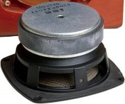
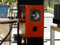
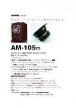
Delivery Source for the 10cm "HR Vocal Driver" from "4722" LENS (47-lab) wanted

Attachments

  • Sakurasystems 4722 lens HR Vocal rear.jpg
    Sakurasystems 4722 lens HR Vocal rear.jpg
    106.5 KB · Views: 371
  • Sakurasystems 4722 lens.jpg
    Sakurasystems 4722 lens.jpg
    684.4 KB · Views: 355
  • AMM AM-105m.jpg
    AMM AM-105m.jpg
    6.6 KB · Views: 111

Why do my front and rear channels go into protection mode when my bass hits

My front channel amp and rear channel amp go into protection mode when my base hits. It only does it when my voltmeter is reading 14.4 volts. My sub and rear channels need 14.4 volts to get the proper power out of them since I have them in mono mode. If my voltage is less than 14.4 ususlly in the 13s I can pound as hard as I want but when the voltage gets up then those two amps kick into protection mode but my sub still hits

450W bass amp: a sextet of GU50s with shunt&current feedback

Hello everybody,

based on:
- the Baby Huey by gingertube;
- the shunt negative feedback;
- "A new look at positive current feedback" ( https://www.americanradiohistory.com/Archive-Radio-News/50s/Radio-News-1957-11.pdf page 56);
- "A new approach to negative feedback design" ( https://www.audiofaidate.org/it/articoli/Crowhurst_NewApproachFeedback.pdf );
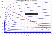
- this thread ( GU-50 Push-Pull AB OT Impedance/Load Line Questions );
- this thread ( Bass Power Amp with GU50 );
- this link for g3 ( http://www.audioxpress.com/assets/upload/files/millet2903.pdf );
- and this link ( http://www.pmillett.com/tubebooks/tubedata/beam_power_tubes.pdf );

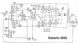
I came out with the attached schematic. It combines negative voltage feedback via shunt feedback with positive current feedback (well, it can be adjusted indeed) connected to the other side of the phase inverter.

Only one mosfet driver is shown, but there will be six, one for each power tube, with six bias controls.

470k and 150k are set to have a voltage drop from the B+ to have approximately 430V for the phase inverter.

I can use shunt feedback because the three GU50s, will have a rp of 8500/3 = 2834 Ohm and gm around 3x 5,5 = 16,5 mA/V.

What do you think about it?

Attachments

  • Roberto-GU50-Bass-Amp.jpg
    Roberto-GU50-Bass-Amp.jpg
    702.3 KB · Views: 1,104
  • GU50 860VB+ 280Vg2 15Vg3 -45Vg1 7kRaa AB2.jpg
    GU50 860VB+ 280Vg2 15Vg3 -45Vg1 7kRaa AB2.jpg
    618.1 KB · Views: 1,075
  • GU50 860VB+ 280Vg2 15Vg3 -45Vg1 6kRaa AB2.jpg
    GU50 860VB+ 280Vg2 15Vg3 -45Vg1 6kRaa AB2.jpg
    421.7 KB · Views: 976

Gentune X-1 Rectifier Alternatives

A Gemtune X-1 amp was shipped to me about two years ago with the rectifier tube broken, so it has yet to be plugged in. I would imagine it had the most common rectifier tube that would come with these. I lost the broken rectifier tube. My question is can a 5U4G (or any 5U4) from the 50's/60's be compatible in this amp. Or, would it be better to go with what it had originally.

Basic in-amp testing

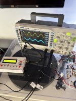
I wanted to run some basic tests on an amplifier I'm building. I have an oscilliscope, and a cheap function generator from Aliexpress.

I hooked it up the way I thought it should be, but I find the signal is pretty noisy.. This is purely from testing as with normal music it sounds perfect, but when hooked up the signal has a hiss in the background and on the scope looks a bit noisy.

1) I connected CH1 oscilloscope probe ground to one RCA ground lug
2) I connected the function generator, via a BNC cable, to the ground lug of the same RCA jack, then ran the function generator signal to the RCA positive lug (which is connected to input connector of the the amplifier channel under test)
3) I connected the second oscilloscope probe to the speaker outputs for the same amplifier.

It works, but signal seems noisy. Anything I should do different?

Attachments

  • IMG_2831 Large.jpeg
    IMG_2831 Large.jpeg
    267.9 KB · Views: 166

Hifonics BRX 3016.1 D Brutus

Hi again, i get this amp, i want to repair for personal use,( i have repaired like a dozen of other smaller amps, some of them are class d,) this is the biggest i Will try to repair.

I've been doing some tests.
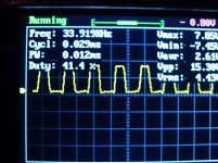
The ps irfp064n are blown and some driver transistors too, i replaced bad driver Ps transistors and i got nice 32 khz square signal, i have in hand irf3205 so for testing purposes i instaled 1 irf3205 per bank(4 in total), the ps worked good with rails of 84 and -84 volts in rectifiers pins, with no output transistors.

In the audio section i found 6 of the eigth fqa38n30 fets damaged, i have in hand stw45nm60 i think this could work, but i have not installed them because i have not worked in the amp this days, there are not another signs of damage ( caps looks good, resistors looks good the driver audio card has no overheating signs)

I have some questions, i hope some one can help me

1.- looking at the data sheet i found irfp064n and irf 3205 almost identical, some diference of course is the encapsulation size. Do you think i can use irf3205 instead of irfp064n with no other problem than the legs and clamp adapting work?
2.- in the audio section, similar question can i replace original with stw45nm60?, in current is 7 amp higher in voltage 300volts higher the rds and capacitances are similar

Some.other tips of this amp.in particular Will be apreciated

The board imaga is for another hifonics 2500 watts but is identical

Thank you!

Attachments

  • DSC_2479.jpg
    DSC_2479.jpg
    506.9 KB · Views: 341
  • 15703147116509056794980958167766.jpg
    15703147116509056794980958167766.jpg
    972.9 KB · Views: 449

Home For My Articles

I recently closed down my website at audiomaker.tech, thinking that the youTube channel would be sufficient.

However, I forgot that I had all my articles and project files hosted there, and I've gotten a lot of email lately requesting copies and such.

I apologize for my oversight, and I'll find a home for them very soon.

Thanks for be patient with the old guy. 🙂

Mike

Purpose and size of caps in Phono Stage

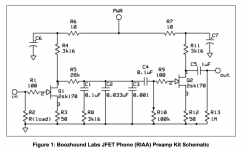
Hi, I am about to build my first solid state build and first phono stage build. The schematic below is for the Boozhound Labs phono stage. I have 2 questions:

1. What is the purpose and recommended size for C6 and C7 capacitors? I was hoping to use some existing 30uF WIMA DC Link caps, but not sure if the uF is large enough for this purpose.

2. I plan on using a Lithium Iron Phosphate battery power supply for the 24V DC. This design consumes 30-50mA, so using a 2AH rechargeable battery pack should give ample listening time. But, most 24V battery packs have built in BMS (Battery Management Systems). I am concerned that the BMS' have some sort of unfavorable voltage filtering, regulation and/or regeneration that might negate the purpose of using the battery (pure DC). Any thoughts on this?

Any input would be appreciated.
Thanks!

Attachments

  • ss 1.png
    ss 1.png
    79.9 KB · Views: 235

Scrap heap Challenge?

I was planning to build an efficient sound system. Another user commented "Good subwoofers don't come cheap."

So, let's play.

I've trolled Ebay. So far I have . . .
TPA3116D2 Class D 2.1 amplifier board: $10.00
19v Laptop PSU (4.7amp) $6.00
12" Driver from Electrovoice Evolve 50 system: $8.00

I still need a box - circa 50 litres.

I hope to make this (reduced power) portable so I'll need a 12v rechargeable battery.

What else will I need?

Wondom JAB problems

Hello everyone,

please pardon my english knowledge, which is a little bit better than not good at all.

I have a probably very simple problem with the JAB's (JAB3+, JAB4, JAB5) in general. I have had several JABs fail over the years and I don't understand why. First I thought, coincidence or application error, meanwhile I think - that can't be, the boards must be able to stand what I do there.

In all cases the boards were supplied with voltage within the specs by a battery. The wiring looks like this:
  • Battery minus to the ground of the board
  • Battery plus via a switch (I tried a relay, too) to plus of the board.

The only board that ran without errors had a LM317 connected in the supply, so that max. 24V arrives at the board. But this could not supply the necessary current for larger volumes, since this (I was not careful while selecting the LM317) permitted only Ioutmax = 500mA.

Can it be that by my circuit (ground board permanently to Bat-Minus) when switching off the board the potential settles to the positive terminal on Bat-Minus, incl. capacitors of the board and then when switching on a current arises, which the board can not withstand? Shouldn't the board be designed to withstand that?

How do you do it, do you all disconnect both terminals with a switch?

Best regards,
Frederik

Help! Classic Cambridge Audio P140x Offset high

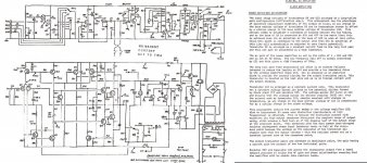
I recapped and repaired a 1973 Cambridge audio P140x. It works good, but has 60mv of offset on the right channel and 180mv offset on the left channel. It has one complementary pair of output transistors for each channel for 70watts (MJ4502LL and MJ802LL). HFE's for one pair is 41 and 86. The other pair is 48 and 134 and is where I think the problem lies. To the right of the schematic I included the theory. The 1st paragraph talks about a self adjusting zero offset circuit. I replaced two tantalum capacitors C30 and 31 and better matched Q8 and Q10 (BCY71's) by swapping them with Q9 (BCY71) which brought down both offsets from 250mv and 135mv to where they are now. Why does this circuit not work? Any help with this would be great! Is there a resistor I can tweak to adjust the offset?

Attachments

  • P140x_DIY.jpg
    P140x_DIY.jpg
    351.1 KB · Views: 203

Pass DIY Update

I just uploaded most of my "classic" (as in old) videos to our Pass DIY YouTube channel. Look for the "Classic Videos" playlist.

I also added Nelson's talk from the 2015 BAF in Palo Alto where he covered the 2SK77B amp and the Schade amp.

I'll be filling in the other BAF's soon.

Also, the companion website for our Pass DIY YouTube channel is now online at passdiy.tv

All of our articles, files, and apps are there! The simulator for Nelson's DIY crossover project, the SIT Modeler, and I just added a Triode Modeler.


I've already closed down my audiomaker.tech website, so going forward, you'll find all my stuff at Pass DIY.

Thanks for looking. Let me know if I missed anything or there's something else you'd like to see there.

Mike

A thought: DSP-Volume->DAC vs. DAC->Analog Volume-Pot

The following situation: A DSP implements a volume control. The I2S goes out to a DAC. If the volume control is only set to say 9 o'clock (room volume), then the DAC does not output 2 volts, but only e.g. 50mV. Isn't this mode of operation bad? The DAC is not linear at this level, has more THD and a bad SNR. In an analog chain, the DAC would be running at nearly 2V and the volume control would be behind it. Best SNR.
  • Like
Reactions: rayma

Using the Jacobian matrix and Excel/Matlab to solve for RIAA network values

Really

Last time I used differential equations and the Newton-Raphson method for valuation solving it was for sinking fund bonds, and securities of companies in bankruptcy. Turns out that no such precision is necessary or warranted! That was decades ago.

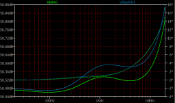
John Ellis, writing in December 2022 AudioXpress proposes an iterative method of solving for the R and C values of the RIAA network which is more precise than Lipshitz's "1A" configuration. This allows for incorporating the value of the "ground resistor" (Rg?) in a conventional feedback RIAA network.

The chart below summarizes the results of his proposed values with those which would be derived from Lipshitz using a very simple op-amp circuit. The difference at 1kHz seems to be about 0.055dB

Attachments

  • RIAA Ellis Graph.png
    RIAA Ellis Graph.png
    8.4 KB · Views: 247
  • RIAA Ellis Sch.png
    RIAA Ellis Sch.png
    8.6 KB · Views: 241

What governs a driver's lowest frequency response?

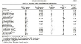
I was comparing the low frequency response of two speakers using a signal generator. Below 25Hz I can't hear anything. The driver's stated frequency response is 45Hz to 3KHz so the absence of audible sound makes sense. To complicate the issue the driver is moving is air and the mirror in the hall is vibrating in sympathy.

The other variable is me. Human hearing is generally quoted as being 20Hz to 20KHz but that's an approximation, and as individuals we are all built to different specifications. This begs the questions: am I personally capable of hearing 25Hz? Does the lower limit of hearing vary amongst individuals. A study of primates show interesting data, show the human hearing to be 31.2Hz to 17.6Khz.

Attachments

  • Hearing.JPG
    Hearing.JPG
    95.7 KB · Views: 335

Another search function query – How to use Advanced options within a particular Thread?

This issue is about how to order search results by Date?

I am trying to use the Advanced search options in a particular thread so that I can Order the results by Date, without much success. So, there are two issues for me here:
1) Using the normal quick Search does in fact return all the relevant Posts I am looking for, BUT they are ordered according to “Relevance” and not “Date”. I prefer Date order – a chronical order in which a particular issue was discussed. Not sure on what basis the Search function decides how relevant posts are to what I am searching for. So, to default this search to “Date” ordered results would be the best solution for me. Not sure how others feel about this?
2) The above should be possible using the Advanced search option, but there is also an issue. When selecting the Advanced search, you can select the “Search threads” option which opens a lot of nice options. However, you cannot drill down to a particular thread. The “Search in forums:” list lists all the forums, but I cannot drill down to a specific thread in those forums. E.g. – If I want to search for posts relating to potentiometers in the “B1 Buffer Preamp” thread under the “Pass Labs” forum, and I want the results ordered by Date – does not seem possible?

Sorry if this has been addressed in earlier threads.

For Sale Arcam AVR 300 / 250 Toroidal Transformers for Amplifier Projects

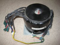
I have 3x Arcam AVR300 toroidal transformers for sale and 1x AVR250 toroidal transformer, 30GBP each + shipping cost. (I'm located in Cambridge, UK). They are all in good condition and taken from working units. I believe the AVR300 transformers are 700W and the AVR250 transformer is 500W. Please see photos.

AVR300
Dual primary, 115/230 VAC
Main secondaries, 29-0-29, 36-0-36 VAC
Minor secondaries, 14, 12-0-12, 8.2, 8-0-8, 4 VAC
Diameter approx 135mm, height approx 110mm
Metal mounting plates are 135mm square.

I'm pretty sure the AVR250 has the same windings except its lower power.

Please message me if interested.

Attachments

  • IMG_2464s.JPG
    IMG_2464s.JPG
    113.4 KB · Views: 212
  • IMG_2465s.JPG
    IMG_2465s.JPG
    51.3 KB · Views: 176
  • IMG_2470s.JPG
    IMG_2470s.JPG
    115 KB · Views: 183
  • IMG_2471s.JPG
    IMG_2471s.JPG
    59.5 KB · Views: 194

Quick poll - How do you like your thread titles to look (classic theme only)?

Yesterday the front page was brought more in line with the fonts and colors that graced the diyAudio homepage for the last 20 years. Which is to say, thread titles appear as nice easy to read regular text and have a bright purple link color. This made the classic theme "more classic" and truer to the pre-migration version of the site.

Much teeth gnashing ensued, with several members voicing their fervent enthusiasm for the bold version of the font to remain for unread threads. The particular font that the pre-migration site used (and the classic theme has always used) is Verdana. It does not have a "medium bold" version. It's either a lovely easy to read screen font as regular (which is how it was pre-migration) or a very thick "extra bold" intended for article titles.

Anyway, a non binding quick poll for those who use the classic theme (only). How do you like your thread titles to look on the classic theme?

Tuning a multi-way in smaart, rephase and REW. Which is best for rephase (truly)

Hi gang ,

So , I was hoping to gather any smaart users that are also proficient in REW and rephase.


So , I have been using REW with rephase and making firs….. took me way longer then it should have to learn it because I’m a clunker. 😛 but I’m a master now!

So , here’s what is going on and maybe someone can help

With REW, I have CSL umik2 and a creative sound card (separate clocks separate devices yah de yah etc etc….

I take 9 gated FDW 15cy measurements around my head. I use REW and shift IR, smooth , time align and vector average…

Send average to rephase for work….
Result is fantastic… my goodness it sounds stunning…

So , I get addicted to pushing the envelope with firs, I’ve emailed lots of ppl and annoying them asking for help… wow some smart ppl on here…. Absolutely brilliant! 🙂


So , in my quest for accurate fast mag and phase data , I bought smaart (v9LE) and I also bought the Roland octa capture as recommended by @Rational acoustics.

I also bought works M23R mics… so I have a nice array of very expensive nice mics…

I spend a month getting it to work right, finally getting decent data…. (Except smaart crashes like crazy) watched all 12 , 1hr trainings for smaart on you tube many times for a few of them.

The smaart tunes do not sound anywhere near as good as my REW tunes…. It’s close but it’s not near as good….

RA says to use 1 mic for phase , although I can use up to 8…. All I want is very clean phase data and quickly…. That’s it , I can do the mag stuff in REW, that’s easy,..

Does anyone know how to get smaart to work like REW in this example? I’m not sure it ever will….

Should I ignore RAs recommendation and do multi mic TF for phase anyway? Or what is the key to get the same results as REW or close to?

I got the measured phase preferctly flat on both side to match exactly, following same rules (phase changes only between 100-1600hz)…. The center image is spread out and blurry… it’s still mostly a good center , but I would expect perfect being mic is directly between my ears. I did all the work on same session, same settings, same volume, same mic placement… same everything… did left and right separate on an OpenDrc..

I hope it’s a setting I’m missing….

Much appreciated…

Andrew

@fluid , @pos

@mark100 , @BYRTT ,

@wesayso
  • Like
Reactions: EarlK

ACE-bass amplifier design

I am very much interested in the ACE-bass principle, invented by K.E. Stahl back in the seventies. I’ve found the patent of the principle and did a lot of searching on the internet. In this tread on DIYAUDIO I found a circuit of a prototype of Bjorno’s ACE-bass amp design.

I am planning to build such a thing to experiment with, and maybe when it give satisfying results build a sub for daily use.

Bjorno mentioned in one of his posts of the tread that the amp part can be replaced by an “gainclone” amp. This would be very practical since I’ve already built a Gainclone amp, which I can use for this project.

I have redrawn Bjorno’s circuit diagram with a Gainclone amp instead of the original amp. My question is: will this work, or am I forgetting some critical things here?

Bjorno, what does P4 (100k) do at the + input of uA748 do? Offset or something?

I am hoping that any of you can give me some feedback on this design.

Thanks,

Durxter

Attachments

  • schema-ace-bass01.jpg
    schema-ace-bass01.jpg
    66.6 KB · Views: 2,874

Ultra-LD Mk3

Opening an old thread.

I have found a couple of these old Silicon Chip/Altronics Ultra-LD Mk3 kits and built them. The amplifiers sound really good but I have a small issue. The gain of one of the amp is sligtly higher than the other one. Any suggestions on how to match them. Is there any way to adjust the gain? I am using them to drive the front speakers in my home theatre. The source is the front channels preout of the Yamaha RX-V6A AV receiver.

Thank you.

Suche DIY Freunden Umgebung Enzkreiz Deutschland

Hi
Meine Name ist Tom, ich habe seit einige Jahren Wohnsitz in Deutschland, bin Niederländer, ab July bin ich im Rente und dauerhaft in Ruit ( Bretten ), ich suche DIY ( Selbstbau ) Freunde in diese Region, ich baue seit 1984 Aktive Lautsprechersystemen, nur als Hobby, keine Kommerzielle. Wenn Jemand Interesse hat, bitte Kontakt aufnehmen, danke,
Gruss, Tojoko ( Tom ).

Catastrophic NAD 7240 repair

Hello all,

Amateur but determined amplifier repairer here. This is my first repair project that I've thrown myself into.

I acquired a previously blown NAD 7240PE from ebay. This unit, when received, had one good channel (L) and one bad channel (R). The initial obvious failures were the main transistors (Q432, Q436, Q426, Q430, Q418, Q428, Q424) and a few electrolytic capacitors.

So far I have replaced every single electrolytic capacitor and the aforementioned transistors. I have also replaced the main transistors on the other side of the heat sync.

My current testing setup from the wall is a Mophorn Variac > 60W light bulb in wired series > NAD 7240PE.

Previously, when I powered on the amp, I could see the bulb shine bright for a few seconds then dim down as the amp began to draw more current.

I had recently replaced R471 and R472 (see center voltage adjustment section, service manual) and replaced the previously removed solder bridges. This is due to R472 burning out from over-current because I accidentally caused a short with the multimeter probe. During my next attempt to perform the center voltage adjustment, I observed a steady 1.5+-0.5vDC of output on the right channel and 0+-30mVDC on the left channel. During this time, turning VR402 resulted in no change in output current.

After a few minutes and restarting the amp, the light bulb wired in series stopped shining when the amp powered on. During this time, I was starting the amp with the variac at 0 and slowly increasing. At one point, I raised the variac to ~20v and the previously good left channel completely blew up and shorted 4/6 of the main transistors.

I am clearly missing something and would greatly appreciate any thoughts and insights into testing processes you would recommend. I'd like to isolate problems before mass replacing components.

I'm also open to cutting my losses and binning this project, just let me know if you think the same.

Attachments

Repurpose an 8 channel lab Instrumentation Amp ? "Trig Tek"

Got this for cheap....up to x1000 gain, 8 independent, single-ended channels. BNC in/outs.
See below for my ideas... what to use this for...audio-wise.....

Trig Tek Incorporated.
Model 208b
20230119_184040[1].jpg
20230119_184051[1].jpg

I contacted the new company (Astronics, link) and inquired about obtaining a manual, as I could not find one anywhere.
They said they no longer have those files for their discontinued products of this vintage.
So, I'm still looking for a manual (or it's younger brother, Model 205b).
The unit is pretty straight-forward, though I'd like to know the calibration process. Each board has 4 trimmers.
Also, each board has an empty 8-pin DIP socket, which I believe is for optional filters (Hi, Low, Bandpass, whatever.....I'm not positive.)
I may have to re-engineer the circuit.

20230119_183546[1].jpg
20230119_183601[1].jpg
20230119_183609[1].jpg

The 16 pin socket connects a ribbon cable to each switch. The 8 pin socket might be for optional filters (??)

All the Lorlin 12 pos. switches were hardly working (no signal).
I opened one up, and found the contacts had a covering of hardened goo. I tested all my solvents, and the only one that worked was Naptha.
There are vent holes in the switch body, so I flushed each switch with Naptha, then blew them out with compressed air. I repeated with Isopropyl Alcohol, and finally a couple drops of DeOxit Gold.....spinning the contacts a lot.
Switches fixed.
Passes clean signals.

Main chip....
PGA207ua ..............5-MHz, 100-pA bias current, FET input programmable gain (g=1,2,5,10) instrumentation amplifier (link)

I assume this was used to amplify load-cells, strain gauges, vibration monitors, or accelerometers.....??

WHAT COULD I USE THIS FOR ??

I'm not sure......mic preamps ? .....piezo-acoustics ? test/measurements ? Making experimental/unusual sounds from tiny signals ?
(I make music and sounds with my modular synth, so.......)

LA6458SS Phono IC Or NE5532

Im trying to build a preamp for my Hitachi Turntable. Its got a MM cartridge.
I know that it worked really well with my Akai Amp. Which used LA6458SS IC. (When the AMP was working).
Ive had a look over the various Pre AMP circuits on Passdiy as well as some other sites.
Ive also been trying to build and test some popular Tone Control Boards that also work as Pre-Amps. These boards all run NE5532 ICs.

Was wondering if some of the more experienced and knowledgeable members could guide me as to which route makes more sense. i.e. Go with a LA6458 IC or one of its compatible IC. Or to go the route of the NE5532. Or if you could explain the difference to a layman.
Right now plan is to finish the NE5532 tone control preamp boards and test them with the Turntable. If it doesn't sound right then scrap the NE route and try building a small PCB just copying the Phono stage from the Akai.
Attacked is the schematic showing how the Akai Phono stage is configured. USing the LA
1660391991687.png

Noise - is it normal level ?

Hi, it is first time for me with class D and i don't have comparison so i have question.
I bought TPA3116 labeled ZK-TB22 Wuzhi Audio looks like this

1494331200_1675272352.png


And i'm experiencing more noise sound than i expected.
1. this is noise that makes bluetooth

Login to view embedded media
2. After disabling bluetooth i can hear this

Login to view embedded media
and this sound can be reduced if i turn on a little both treble knobs
3. Sound without blue tooth and treble knobs turned up

Login to view embedded media
4. But this sound is still way off in comparison to my cheap creative example:

Login to view embedded media
To avoid power supply interference i connceted amp to battery and did not connected aux.
So is it normal ?

Harman Kardon 730 Speaker pop on power on

I'm taking another look at one of my own units that has been at the back of the line for ages.
It was occasionally blowing rail fuses and sending a big pop to the speaker when it did that. We fried a tweeter with it once. One of those issues that was infrequent enough that it is very hard to track down.
But it still puts a decent pop through to the speakers on every powerup unless I wait 10 or so seconds to turn on the speaker. I had another one of these units a few years before I got this one that did the same thing. But I had another client unit in recently that didn't pop at all. I could just leave the speaker switch on. I know many units that don't have a speaker relay still have some sort of circuit to prevent this pop, but I can't find one here. Is there one I have missed?

I've added a premade protection circuit but it clicks in a bit too fast. I have to figure out how to lengthen the delay a bit, but after seeing the other 730 that didn't pop at all, I'm wondering if there is something that is supposed to prevent this pop completely.

I've recapped it and done as many other things as I could think of, but never cured the issue. Power amp transistors are original, except I changed the input transistors with a new matched pair.

https://www.hifiengine.com/manual_library/harman-kardon/730.shtml

All Cee's PSU for Class AB Amp

This PSU arose out of a need for compact, low-cost PSU for the FH9HVX.

The All Cee's PSU features up to 40,000uF of bulk capacitance at up to 63vwdc. You can install a 0.22R to make it a CRC vs a CC PSU if you desire even lower ripple. Tests show that 20,000uF per rail sounds best in the FH9HVX with no hint of audible hum and a huge reserve for bass impact. Other features include provision for a snubber on the trafo input, bleed resistors, film bypass caps, LED charge indicators, and an on-board NTC ground loop breaker for connection to the chassis/protective earth ground. You can use all Faston tabs or the alternative Wurth 0.250in tab arrays which make it easier to install and keep aligned. All of this is a compact 80mm x 100mm package that will be easy install inside your chassis. If you are running your FH9HVX below 50v rails, you have enough room to install 15,000uF caps for even better performance. The caps in the BOM have been selected for the high ripple current to enable continuous higher power operation if needed. For higher power operation, it is advised to mount the bridge underhung and bolted to a metal floor plate for heatsinking.

Errata Jan 8, 2021: note that maximum diameter of main bulk caps is 30mm, not 40mm as stated on the schematic. 30mm dia snap in caps fit there best.

850136d1591375406-fh9hvx-budget-conscious-100w-class-ab-lean-times-cees-psu-schematic-v001-jpg


850135d1591375406-fh9hvx-budget-conscious-100w-class-ab-lean-times-cees-psu-3d-render-v001-jpg


850137d1591375406-fh9hvx-budget-conscious-100w-class-ab-lean-times-cees-psu-stuffing-diag-v001-jpg


This PSU is available in my shop for $20.

866635d1596916646-cees-psu-class-ab-amp-cees-photo-jpg


BOM here:
https://www.diyaudio.com/forums/att...00w-class-ab-lean-times-cees-psu-bom-v001-zip

Shopping cart for BOM here:
FH9HVX - Budget Conscious 100w Class AB for Lean Times

Thank you to JPS64 for another super layout!

Attachments

  • All-Cees-photo.jpg
    All-Cees-photo.jpg
    298.5 KB · Views: 2,332

Sony VFET PS filter

I have a DIY Sony VFET Kit. To say the least I am new at this. I am building the Bulwar front end, would like to get help in building the PSU filter. The build by 6L6 has been very helpful. A thank you to him. I hope to find the PSU filter board and parts, so far I have had no luck finding them. Most parts are available, however I have a question about the C1 nichicon cap. I see the rated voltage and capacitance...do the leakage current, impedance and rated ripple have to be known when ordering? A detailed list would be extremely helpful. Thank you in advance

WSA230 amp Q's

I happened upon this hi powered PPP design and was surprised that a single cathodyne was used to drive this quad.
The signal caps are unusually large off the plate and cathode... the current supply through inverter is much the same (30k & 30K) as what is common in most 10-30W PP amps

So-
I'm wondering if this amp design is either flawed or limited due to this? Or if the 8417 outputs are special in some way to allow this?
They are expensive...
https://tubedepot.com/products/8417?
Jim

Attachments

  • WSA230.jpg
    WSA230.jpg
    465.6 KB · Views: 91

Faital Pro 12FH500 Driver Measurements in DATS versus Specifications

Madisound had a special on the Faital Pro 12FH500 12" Woofers, so I picked up a couple. The measurements in DATS are quite different from the mfg published specifications. For example I measured Fs at 67 hz. and the specification is 45 hz. See my DATS measurements below.
But, both drivers measure very close to each other and I have not broken in the drivers. For my purposes I am not too troubled by the discrepancy in measurements, I was interested in experimenting with a neodymium magnet driver with high efficiency and low Q and I always planned to use measured values. But, this might suggest this driver might not provide as much LF extension as some might be expecting from the published specs.

* This data was exported from the Dayton Audio Test System: DATS
*
  • Piston Diameter = 0 mm
  • f(s)= 66.82 Hz
  • R(e)= 5.34 Ohms
  • Z(max)= 64.63 Ohms
  • Q(ms)= 4.897
  • Q(es)= 0.441
  • Q(ts)= 0.4046
  • V(as)= 0 liters (0 cubic feet)
  • L(e)= 0.9781 mH
  • n(0)= 0 %
  • SPL= 0 1W/1m
  • M(ms)= 0 grams
  • C(ms)= 0 mm/N
  • BL= 0
  • K(r)= 0.04387
  • X(r)= 0.5812
  • K(i)= 0.07071
  • X(i)= 0.5486

Attachments

2SJ50/2SK135 Hitachi

I have twelve of each original matched 2SK135/2SJ50. 24 units for make a project with a lateral mosfets.
I have 12 pairs, if you can make me an offer for all together, it is an opportunity because they are original and I have had them for a long time.

I also have the transistors of the A75 Thargard-Pass, all paired and those of the original project. I also have them for a long time but I have given up building anything, this comes with the pairing details, individualizing each transistor with its details written on a guide.
If you are interested in either of these two you can send me a private message.

So I bought a peak hold voltmeter, now what?

Now I'm wondering...how do I tell what this thing
https://smile.amazon.com/gp/product/B07R47RYPW
is actually capturing? The idea was to-in the absence of a storage oscilloscope-use the peak hold function to determine if an AVR is clipping.* But now I wonder how fast is it, is it really getting the peak of the peaks.
???

*by calculating the voltage rail from the all-channel power spec and comparing. If well below, not likely clipping. If well above, clipping. If near, gee try to borrow a storage scope...

Junior phono

Hello,

with the nr. 418 of Audioreview in Italy I have presented a phono tube circuit with the pcb.
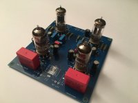
In photo the boards completely mounted.
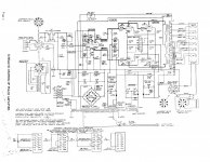
It is a passive riaa.
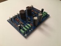
In the second photo there is a board for HT regulated with fet; it is dual mono.
In addition there is an other HT regulated but with a single Fet. This is a less complicate otpion.
Last photo is a pcb for supply for filament with a LM350T.


Walter

Attachments

  • phono.jpg
    phono.jpg
    749.3 KB · Views: 960
  • HT dual.jpg
    HT dual.jpg
    904.3 KB · Views: 917
  • HT_single.jpg
    HT_single.jpg
    824.2 KB · Views: 847
  • Fil_reg.jpg
    Fil_reg.jpg
    720.5 KB · Views: 832

Stasis Nakamichi Amplifier Help

Long time forum reader and first time posting. I am a long time electronics tinkerer, and recently acquired some Nakamichi equipment that was, according to the WWW, designed by the famous Nelson Pass. It was this fact of Mr. Pass's influence in these amplifiers that got my attention (since I just built two ACA 1.8 amps). I ended up with two PA-7 Stasis amplifiers, a CA-5 preamp, and a CA-5II preamp.

The first thing I noticed was that the CA-5 sounded waaaay better than the CA-5II. At least to my ears. The CA-5II may need some attention - or a new owner.

The PA-7s have me a little worried. They don't seem to have much top end sparkle. The have an extremely nice midrange though. I'm not sure if I need to make some adjustments to the DC offset or bias settings because of age, or if I should look into doing a recap at this point. I was much younger when I first heard these amplifiers. I remember being incredibly impressed with the PA-7 driving some reference level Infinity speakers. Any recommendations on what I should do with the PA-7s?

Kicad symbols for Elma?

Hi friends
Very first steps into Kicad, I am getting along quite good (for my level), but I absolutely don't find symbols for a rotary-switch I am using: a Elma 01 2 channel 3 position 60° switch to be precise...
I would bet there's symbols around for all those Elma variants, but where?
Has anyone a good source? Or hoards his own library you'd be willing to share?
Thank you so much!

Adcom GFA 555 MK1 input board econo safety refresh.

Hello all hope everyone is doing well and remaining warm.

My amp is an Adcom GFA 555 mk1.
I have read in several places now that aging transistor drivers can wipe out our inline speakers. I'm making some time to refresh those and maybe whatever else would be adviseable while im in there, hence this post. Im trying to remain as economical as possible(on a budget) and focusing on making sure those drivers dont burn out as well as upgrading what is absolutely likely to have degraded and may be affecting sound quality. I will be doing a thorough refresh all sourced from Hoppe, his designs are the inspiration in this 'safety refresh'.

I will be opening up the amp to both test as many components as possible while I address the input board at the same time. The amp is working fine. I do not expect to discover filter caps or other caps as bad. But one can never know what you might find when you start taking measurements so whatever I find is truly out of wack from specs I will order and replace. Please offer advice on components that shouldnt be skipped out on due to age or to assure sound clarity or if you see anything listed as a mistake. So far I have come up with the below to be replaced for certain:

The main culprits of disasters;
(T0126 transistors):
Q7s,Q6s = will recieve KSA1381ESTU
Q4s = will receive KSC3503DS

Both Q7s and Q4s will also receive heatsinks. Q6s do not necessitate.

(T092 transistors):
Q1s and Q2s = will receive Hoppes matched pairs KSC1845FTA

(TO220 transistors) for the Output boards: Please which paste and which thermistor(1)?
Q11s = will receive MJE15033G
Q12s = will receive MJE15032G

.1% Precision resistors in the input path for gain precision:
R1s,R5s = will receive RN55E1001BB14(1k ohm)
R2s,R6s,R223 = will receive RN55C2212BRE6 (22k1 ohm)

I feel the above will limp me by for awhile until a full complete Hoppe overhaul in near future. Obviously any components found out of wack will require another parts order.

Please let me know if there are specific caps or anything else that you think is absolutely indispensable must do's while I am in there. With a little luck I'll go in do these upgrades and come out without needing anything else additonal. Fingers crossed. I know some people swear you must do filter caps but if they are not out of wack specwise I think I will leave them in place unless its factual that simply their age effects sound? I will be adjusting bias before I bottle her back up as per Adcom manual.

I was also considering the adjustment pots. Please advise if og are really that bad.

Thank you for your time.

This amp drives fully restored to original specs Polk M10s.

Denon DP-1200 (Remove motor/platter/bearing from old plinth to new)

Hello:

I have been staring at this for a couple days now, and figured I would try the experts before I ruin the motor. I have a Denon DP-1200, and want to use the motor/platter/bearing (without the tonearm) in a new plinth (with a new tonearm). The DP-1200 is a semi-automatic, so the motor won't run unless the on/off lever switch is on AND the tonearm has been moved away from the armrest. There is a circuit board KU-255B that controls the arm sensor.

I am okay with soldering and staying safe while working on this; however, I cannot read a schematic to save my life! I have attached a PDF of the schematic as well as a photo of the motor and circuit boards). Three questions:

1. I believe I can take the two red wires currently attached to the on/off/standby switch and connect them to a DP-DT toggle switch and use that to turn the motor on and off. Am I correct in this?

2. How do I remove the KU-255B circuit board (and all of its tonearm functions) from the circuit? There are four wires (W-13 (Orange), W-14 (Yellow), W-15 Gray and W-16 (Black) that run from the Servo Amp Unit KU-255A to KU-255B. If I just desolder those wires from the Servo Amp Unit, will the motor still run? (I'm wondering if the KU-255A board needs to sense voltage on one or more of those wires in order to provide power to the motor?) Is it possible to connect one or more of those terminals together on the KU-255A board so that it "thinks" the KU-255B board is there and telling it to provide power?

3. I am not sure whether any of W-13 (Orange), W-14 (Yellow), W-15 Gray and W-16 (Black) are ground wires (though based on its location on the KU-255A board, I believe W-16 (Black) is ground). If I remove the KU-255B board from the circuit, will this impact the ground of KU-255A (or anything else) in any way?

Thanks very much in advance for any help provided.

Attachments

  • page 19 (2).pdf
    page 19 (2).pdf
    467.3 KB · Views: 118
  • IMG_0792.jpg
    IMG_0792.jpg
    691.1 KB · Views: 232

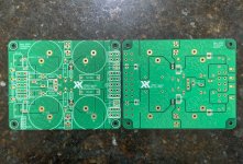
PCB for Peak Voltage and Current detector

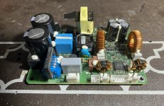
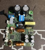
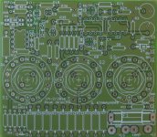
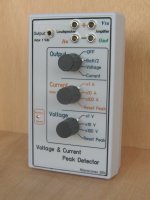
I have a few PCBs (shown in Photo) for the construction of a Peak Voltage and Current detector (shown in the other photo) as was presented in my article for Audioxpress (March 2015).
The device can be easily inserted between the amplifier and the loudspeaker and will measure the peak voltage and the peak current during the reproduction of a real music signal.
The price for the PCB is 25 Euros plus shipping.
Due to copyright, it is not possible to upload the article, but if you have read the article and interested, send me an e-mail at gntanavaras@gmail.com

Attachments

  • Peak detector PCB.jpg
    Peak detector PCB.jpg
    167.1 KB · Views: 598
  • The Peak detector device.jpg
    The Peak detector device.jpg
    353.4 KB · Views: 595

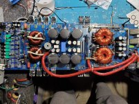
Rotel RA-840 DC voltage on one channel

Hi guys, I've got this immaculate Rotel ra-840 that looks very well cared for. There is not a single piece of fluff anywere inside! With no load I've got 11mv on one channel (regardless of source selected) and 2.4 (ish) volts on the other channel. One fuse on the combined pre/power board is blown. I'm seeing 21 volts on that (see pic) and 15mv on it's neighbour. There's 76volts coming from the supply board, does that sound right?
I built a chip amp some years ago but I've forgotten most of what I learnt. I have noticed a lot of the joints are dark grey as opposed to shiny but no components seem loose/wobbly. Any thoughts for a willing learner?
Fuse highlight diag.png
Screenshot (86).png
Screenshot (87).png

Triggering my PA amp

Hi
I used to use a one click extension lead to power on my hidden pa amp for my subwoofers
My av amp used to be plugged into the main socket so when that was turned on it used to power the other sockets to my pa amp

I’ve now switched to a minidsp pre amp this will not power the other sockets on when it’s turned on presumably because it has a 12v power supply

Anyone have a work around I can use to power up a av amp using something with a 12v power supply

Thanks

Bouyer As240 revisited for a new life

hello to all, here I have at my disposal 4 Bouyer type AS240 and 245 amplifiers which are intended to work mainly under 100V line, their design had been made for this but they can also be used under 4 - 8 or 16 ohms thanks to its output transformer.I used about ten years ago it's amplifiers for car races or noises and quite important with as loudspeaker 100V line horn type IT-50 from Monacor. as the power of this amplifier is 240W rms at 480 W peak,and the number of speakers that I had to place was too large, I turned to QSC type ISA800T amplifiers which are dual mono but with more power available for less weight: 2 bouyez are 52 KG for 2 x 240W, the QSC isa800TI weighs 26 KG for 2 x 800 Watts knowing that the power to be used must be 68% for the 100V line.
to get to the heart of the matter, I would like to be able to use the 4 output transformers whose primary impedance is 2 ohms defined on the Bouyer plan, so I'm looking to make an amplifier with 4 x 100v line output and an SMPS power supply preferably to maintain a reasonable weight and therefore I am looking for an amplifier under 2 ohm load not too complicated to make or so as on sale on aliexpress in this style:
https://fr.aliexpress.com/item/4000....0.0.2175378dBIRjDi&mp=1&gatewayAdapt=glo2fra
https://fr.aliexpress.com/item/1005....0.0.2175378dBIRjDi&mp=1&gatewayAdapt=glo2fra
SMPS:
https://fr.aliexpress.com/item/4000....0.0.2175378dBIRjDi&mp=1&gatewayAdapt=glo2fra

in summary: a common power supply with 2 stereo modules or 4 mono modules, I only plan one potentiometer per channel as well as their individual power switch and for their signal inputs it will be by mixer which will have all these preamp functions and tone corrector. only thing that seems important to me and to have 4 VUmeter output to keep an eye on their output level.
I have no feedback from these amplifier boards. ( original schema As240 -245 with 12 x 2n3055 transistors output )

Phil
BOUYER AS245a.jpg

USB PC oscilloscope. Dual channel. 18 mega samples/s

Dual channel PC USB oscilloscope.
18 mega samples. Up to about 1MHz bandwidth so ok for audio work or low frequency digital work.
Analogue display and spectrum analyser display.
Trigger is none, positive and negative.
AC/DC switches.
Data logger mode for saving a stream of captures to a pc file.
Print out screens.
Comes with USB scope interface and CDROM and instruction sheet.
Requires x10/x100 scope probe. Not supplied.
£30 including p+p to UK only.


1600.jpg

Ideas on old preamp repair

I recently shipped an ancient Threshold FET 10/pc preamp to my son. It was working last time I used it but one channel was DOA when it arrived. I have the unit back and am contemplating a repair strategy. Given that the unit is at least 30 years old I'm thinking beyond just hunting down a bad semiconductor or whatever. Bad solder joint from rough shipping? A bad electrolytic? Combination of things or cascade of failures? Regardless, I want to get it fixed for another 30 years.

Thus far I have located the point on the board where the input signal goes dead. Power supply works fine and no sign or anything burnt. So, what I have in mind is:
  1. recap everything and reflow all the joints on the board on principal (eliminate those potential sources of failure and reduce liklihood of future failure)
  2. diagnose what's actually blown and replace accordingly if the above doesn't fix it.
Is this a reasonable strategy or am I just making work for myself? I haven't found have a schematic or any other tech info that might help. I'd call myself maybe an intermediate hobbyist at this stuff (worked in stereo repair shop ages ago, have simple bench setup of a scope, AC voltmeter and signal generator). Comments and ideas would be very welcome. Thanks,

Technics SU-A900Mk2

New on this forum!

I have a full Technics stack (bought in 1999) and has worked perfectly fine for years, however, I now seem to have a problem with the phono.

All the rest (CD, MD, Tuner, Aux etc) all work fine, but have a static hum when amp is set to phono even if the deck is not powered on and the banana leads are disconnected.

This seems to point to the phono stage internals.

Is this something the could be repaired? If so, any idea how much would that cost (am in UK)?

Or is it worth me buying a used serviced model from a reputable dealer or P/Xing the existing one for a replacement?

thanks
David

Martin Logan CLS2 Electrostatic Speakers

Hey all,

Have to continue unloading some collected Gear...

A Pair of Martin Logan CLS2 Electrostatic Speakers with Oak (?) Frames in very good condition. The panels have no noise issues and have no stator separation, and are clear of any crud on diaphragm.

Interfaces appear to have the caps upgraded to PP caps (by previous owner).

Pick up only for now in West Sub of Chicago....Audition advised to confirm proper operation.

How's $1350 for these classic speakers?

Attachments

  • 00b0b_8EKJFAUYX4Zz_0CI0lM_1200x900.jpg
    00b0b_8EKJFAUYX4Zz_0CI0lM_1200x900.jpg
    98.3 KB · Views: 128

Unity gain buffer

Hi there...
for driving pair not so usual amplifier for my open baffle speakers I need some transparent unity gain buffer stage that will supply audio signal to my amps. Buffer stage must have low output impedance in order 50…200 ohms. My preference is all discrete technology, without IC. My amplification setup have 2x24Vdc and 30Vac sources (and any derivate from this voltage is possible). So, any recomendations for that type of buffer stage?

Thank you all for helping me on this and given ideas..Dubravko from Croatia

Thoughts on Vinyl Mastering

They were expected to do this with media which didn't allow for this ( vinyl). With digital media there is no issue letting low end phase issues and customers don't ask for it to be monoed, then... responsability is now on producer/ recording-mixing engineer/artist.
The (vinyl) recording engineers were expected to do this, just like I was expected to clean my room when I was a teenager. Sometimes it did actually happen.

X100 backengineered here

X100 backengineered

X100.GIF


I am very interested in feedback on this design (which is based on patents held by http://www.passlabs.com and thus not available for anything but research). To scale power, simply change rail voltages (and increase value of feedback resistor to get enough front-end voltage gain to drive outputs to saturation). To change level of Class A drive, increase bias resistors. To improve "supersymmetry" and reduce gain, increase value of resistor between bottom of input FET's.

The 1M resistors are there for simulation purposes and would ordinarily be smaller. And yes, I simulated this design using a Spice CAD package.

We are probably looking at something very close to a commercial X-series amp (without embellishment). If you like feedback, place the feedback loop around the output transistors.


[Edited by Petter on 02-21-2001 at 07:52 AM]

Marantz CD273

Don't think ive ever posted here before but have read the board for quite some time.

So first of all hello,

I've got a few CD Players but the one I use most is a CD273, mainly because I like the Size and it plays well.

Is anything worth changing, Any recommendations?
Op amps already able to be swapped and most caps have been changed due to its age, But any worthy gains that can be achieved?.

Many thanks.

Attachments

  • cd273.jpg
    cd273.jpg
    991.8 KB · Views: 718

What sort of power can a vintage 12" speaker produce, at the very least?

I have a 70's guitar combo amp which I use with my basses - an FBT Jumbo 100. I bought it thinking it's a 100W unit, especially because it's kind of enormous. Turns out, it's a 10W amp. When I open it, I see it has a 12" speaker.. I'm planning to replace the PSU and amp circuitry in it, so I can get about 30W out of this. However, should I keep the speaker? The text on the speaker doesn't give any hint on what is its power. rating. All I could find online is that it's an old Philips unit, and that it has a nominal impedance of 4 ohm, which I could confirm myself, but no firm info on power.
So the question is: what is the lowest power 12" cabinet speaker's power output? I would be surprised if it were only 10W.
FBT_Jumbo_100_speaker.jpg

Flat Wall Mount Stereo MLTL using TC9Fs (2)

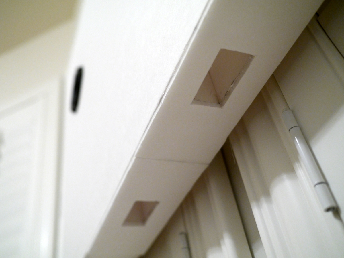
This thread is being started as an OT discussion from the Tabaq thread. The design is a compact flat wall mountable stereo speaker that has great midrange clarity and pretty decent bass extension due to the mass loaded transmission line (MLTL) approach that was added to the original design based on this thread. The original open-ended TL design looked like this:
2011-05-26170029_74434.png


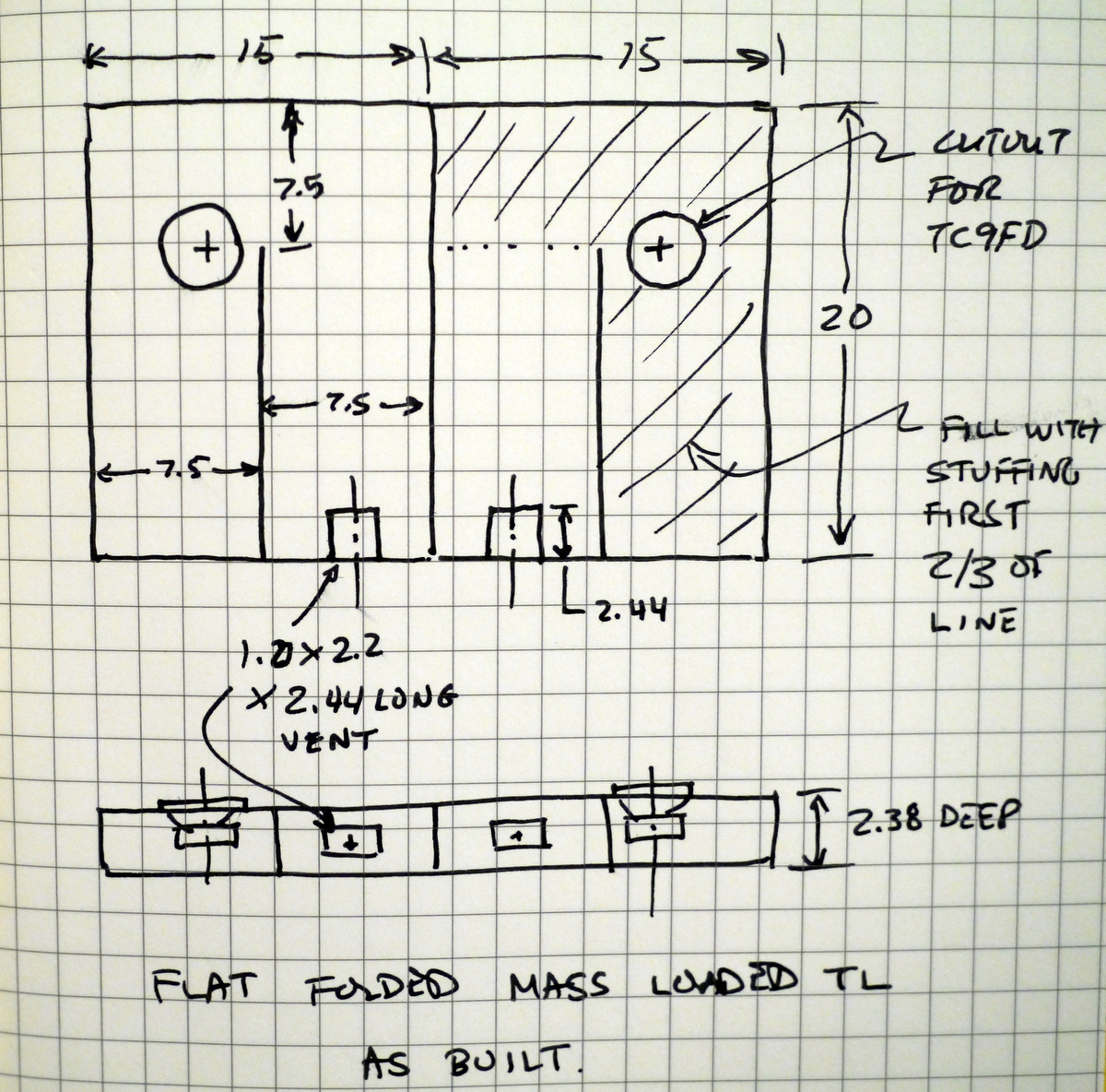
I modified the dimensions of that design to fit two speakers on a single panel of 20in x 30in foam core board. The revised design plan is as follows (added 1.0in x 2.2in x 2.44in long vents):

334670d1362710759-foam-core-board-speaker-enclosures-p1040134.jpg


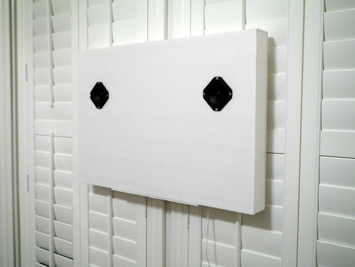
Here are some photos of what it looks like:

334668d1362710759-foam-core-board-speaker-enclosures-p1040132.jpg


Close up of the constrictor vent:

334669d1362710759-foam-core-board-speaker-enclosures-p1040133.jpg


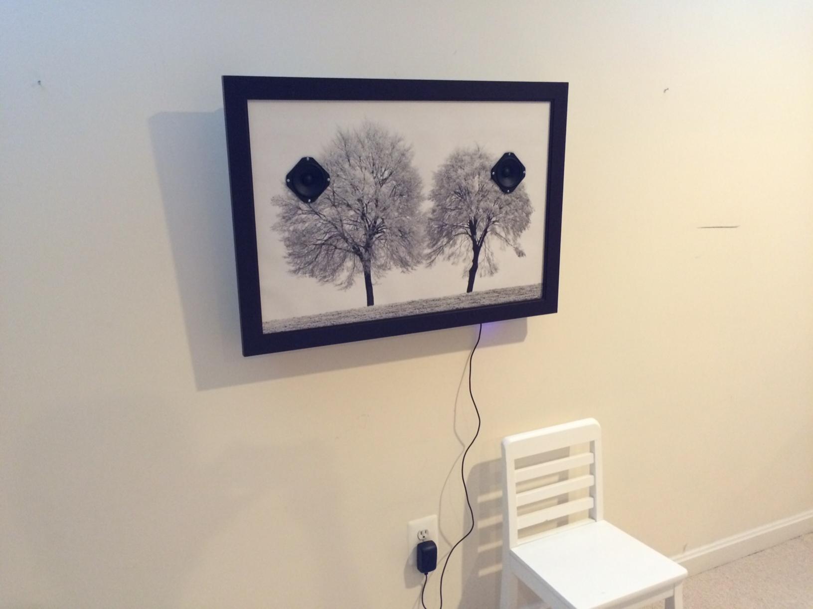
If you want, you can decorate with a picture frame (the craft stores have a ready-made 20in x 30in frames in stock) and a poster or picture to look like this (this one has a built in class D amp and BlueTooth connectivity in addition to 3.5mm stereo jack):

496443d1438359290-flat-wall-mount-stereo-mltl-using-tc9fds-wall-mltl-framed.jpg


Several people have built this with good success. Some have split it off to be a single (non-stereo) speaker.

Here is a sound clip:
diyAudio

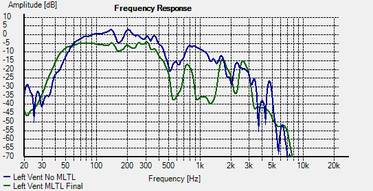
Here are measurements of the vent bass output:

334671d1362710759-foam-core-board-speaker-enclosures-flat-mltl-freq-resp.png


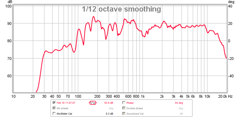
Here are more recent measurements from a meter away with speaker mounted on wall at 53in driver height from floor. The wall and room combine to extend the bass to a very deep 30Hz, albeit lower amplitude (but still very present). The drop off below 100Hz is due partly to room modes and also just fall off with distance:

496448d1438360794-flat-wall-mount-stereo-mltl-using-tc9fds-flat-mltl-fr-1m-53in.png


The impulse and step response are quite nice:

496449d1438360794-flat-wall-mount-stereo-mltl-using-tc9fds-flat-mltl-ir-1m-53in.png

Please advise! I want to fix my parents AudioLab sound system.

Please help!

My parents have an AudioLab 8000p and 8000c separate pre and power amp.

The system served them well for many years but a while ago a fuse went on the house fuse board. The speaker let out a massive bang and the pre/power amp stopped working, despite the fact they were meant to have overload protection.

They were originally very expensive so they seem worth repairing, but at the same time I don't want to spend lots of money to be told it's not repairable etc.

I would love to fix this for them but have no idea where to start as I don't know much. Any advice would be much appreciated!

Thank you!

How much Watt if using MJE15030/31 as output in power amplifier?

MJE 15030/31 data TO-220:
Continuous current: 8 A
Peaak current: 16 A
Total dissipation: 50 Watt
Max temp: 150 Degrees C
Rjc: 2.5 C/W

Where is the Watt limit, would you say, when using MJE15030/31 as output devices?
Is there some good option to use when choose TO-220 devices?

I also have considered MJE3055T/2955T. 10 A and 75 Watt. 1.67 C/W.

XSIM scheme + filter response of KEF Reference Model Three

Hello Gents,

Kinda started with crossovers about a week ago so pretty noob to begin with. Studied Allens famous article of course and some online tutorials. I know what capacitors, Inductors and resistors do and understand the math that comes with it but I'm fairly new to audio in general.
Picked up a couple of Kef Reference Model Three's recently and although they sound majestic to my ears I also use them to learn more about crossovers. I've got the actual scheme + vlaues from this forum and started playing with XSIM. I don't have the specific drivers specifications. The only thing I have is:

Frequency Response: 40Hz to 20kHz
Recommended Amplifier: 50 to 300W
Crossover Frequency: 140, 400, 3000Hz
Impedance: 4Ω
Sensitivity: 91dB
Bass: 2 x 200mm B200 pulp cone
Midbass: 1 x 160mm B160 polypropylene cone
Midrange: 1 x 160mm MB160 polypropylene cone
Tweeter: 1 x 25mm NT25 soft dome

Here is the basic scheme and the filter responses. Now the question is whether or not there's room for improvement or does that all come to presonal preferences mainly?
Note: I'm going to replace the bipolar caps and resistor from Bennic with better ones so it might be a good idea to each some values here and there as well.

Comments much appreciated...

regards

Willem

filter-response.png
scheme.PNG

Silly Wok-Fi build. It works!

PiePan1.jpg


If you have never heard of Wok-Fi it’s the practice of building Wi-Fi extender antennas from Asian cookware, sieves and the like.

Out in the barn there is a seismometer that needs Internet access to upload data. Rather than run a lot of CAT5 underground it’s linked with a Wi-Fi extender to the house network. Easy. But out there it’s at the edge of its range and likes to complain that it is "too far from the router."

So I kludged up this monstrosity. Just two aluminum pie pans glued together. Not parabolic at all, and it even won’t focus light. I poked the antennas through the back side and pointed it at the house.
PiePan2.jpg


It works! It gives me 12dB gain on average. Can’t quite believe it. Perhaps there will be a more elegant solution in the future, but for the moment I’m happy.
Projects by fanatics, for fanatics
Get answers and advice for everyone wanting to learn the art of audio.
Join the Community
507,604
Members
7,879,178
Messages

Filter

Forum Statistics

Threads
405,825
Messages
7,879,178
Members
507,604
Latest member
Ahaudio