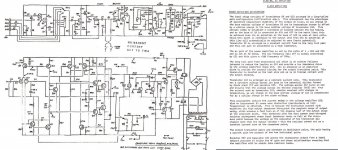
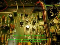
I recapped and repaired a 1973 Cambridge audio P140x. It works good, but has 60mv of offset on the right channel and 180mv offset on the left channel. It has one complementary pair of output transistors for each channel for 70watts (MJ4502LL and MJ802LL). HFE's for one pair is 41 and 86. The other pair is 48 and 134 and is where I think the problem lies. To the right of the schematic I included the theory. The 1st paragraph talks about a self adjusting zero offset circuit. I replaced two tantalum capacitors C30 and 31 and better matched Q8 and Q10 (BCY71's) by swapping them with Q9 (BCY71) which brought down both offsets from 250mv and 135mv to where they are now. Why does this circuit not work? Any help with this would be great! Is there a resistor I can tweak to adjust the offset?
Attachments
Hi gaff,
Sounds like you have your amp working reasonably well, but you can trim offset to a lower value by tacking in an experimentally chosen resistor, specifically between C31 and a power supply rail. I can lead you through the calculations.
Would you advise me of some resistor values not shown in your drawing: R56,R57,R60,R62.
And some voltages:
Base Q8
Base Q10
Volts across R60 (ideally 0mV)
Offset at amp output (please indicate negative offset as negative values.)
Supply voltages
Thanks!
Hi BSST,
Thanks so much for your help!
Values:
R56 = 39K, 1/4W, 5%
R57 = 1K, 1/4W, 5%
R60 = 750 Ohms, 1/4W, 5%
R62 = 39K, 1/4W, 5%
Voltages:
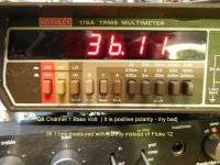
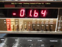
Base Q8 channel 1 = -39mv, channel 2 = +28mv
Base Q10 channel 1 = +20mv, channel 2 = +33mv
Across R60 channel 1 = 1mv, channel 2 = 1mv
Channel 1 offset = -167mv, channel 2 offset = -64mv
VCC:
Plus rail = +45V
Minus rail = -45V
Preamp circuts = -22V rail and ground
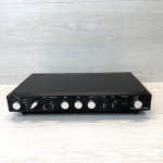
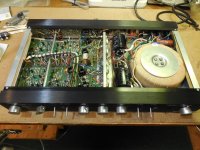
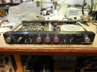
I attached a couple of photos of this cool vintage amplifier too. This is the first ever amplifier to employ a toroidal transformer.
Gary
Thanks so much for your help!
Values:
R56 = 39K, 1/4W, 5%
R57 = 1K, 1/4W, 5%
R60 = 750 Ohms, 1/4W, 5%
R62 = 39K, 1/4W, 5%
Voltages:
Base Q8 channel 1 = -39mv, channel 2 = +28mv
Base Q10 channel 1 = +20mv, channel 2 = +33mv
Across R60 channel 1 = 1mv, channel 2 = 1mv
Channel 1 offset = -167mv, channel 2 offset = -64mv
VCC:
Plus rail = +45V
Minus rail = -45V
Preamp circuts = -22V rail and ground
I attached a couple of photos of this cool vintage amplifier too. This is the first ever amplifier to employ a toroidal transformer.
Gary
Attachments
It's not a servo, so it does not correct to zero output offset voltage.
The DC voltage gain is unity. That probably means the input circuit is a little out of balance.
The DC voltage gain is unity. That probably means the input circuit is a little out of balance.
You should double check polarity at base of Q8 channel 1. It's a PNP transistor, so base current should produce a positive drop across R56+R57.
I'm guessing your DVM has 1mV resolution, so there's quite a bit of imprecision in the voltage across R60. At face value, 1mV across 750 ohms implies 1.33uA flowing through R60; this current flows through R62, producing a -52mV contribution to offset. Nichicon has a series of low leakage caps that might offer lower leakage than then tantalums.
The added resistor trick injects a small current to trim out the offset and it connects to the -45V rail, since your offset is negative. Its value:
R(trim) = 39k*45V/Offset eg. 39k*45V/ 0.167V = 10.5M ohm.
You can insert a 100ohm trim-pot at the emitters of Q8 and Q10 with the wiper of the pot connected to the tail (TP12). This will mean cutting the emitter's traces in order to inset the pot. But now you can trim the offset to +/-10mV (it will drift a bit). The added benefit is that the differential long tail now will have de-generation witch will lower distortion in this stage. Before you install the pot, make sure it has ~50 ohms on each side of the pot - meaning having the viper in the middle position. To make your life easier, please use a muli-turn trim-pot. 🙂
https://www.ebay.com/itm/403010735894
Good luck.
https://www.ebay.com/itm/403010735894
Good luck.
You should double check polarity at base of Q8 channel 1. It's a PNP transistor, so base current should produce a positive drop across R56+R57.
I'm guessing your DVM has 1mV resolution, so there's quite a bit of imprecision in the voltage across R60. At face value, 1mV across 750 ohms implies 1.33uA flowing through R60; this current flows through R62, producing a -52mV contribution to offset. Nichicon has a series of low leakage caps that might offer lower leakage than then tantalums.
The added resistor trick injects a small current to trim out the offset and it connects to the -45V rail, since your offset is negative. Its value:
R(trim) = 39k*45V/Offset eg. 39k*45V/ 0.167V = 10.5M ohm.
Hi BSST,
You are correct on the polarity. See attached for revised measurements for channel 1.
I'm not quite clear on where to connect the resistor -45v to ???. I have some new Tantalums ordered.
C30, 3.3uF @ 16v and C31 47uF @ 6v. I think I bought 35v caps.
I also like the idea of trim pots. Would it make sense to change Q8 and Q10 with a modern (zetex?) diff pair. If so, any ideas on a suitable replacement for the two BCY71's. a sngle can would be difficult as the transistors are not next to each other.
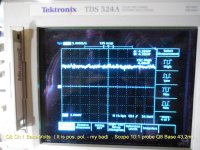
I did test the distortion with my HP 8903A analyzer and the THD unloaded at 1khz was .2% (the Cambridge spec says .1%).
Gary
You are correct on the polarity. See attached for revised measurements for channel 1.
I'm not quite clear on where to connect the resistor -45v to ???. I have some new Tantalums ordered.
C30, 3.3uF @ 16v and C31 47uF @ 6v. I think I bought 35v caps.
I also like the idea of trim pots. Would it make sense to change Q8 and Q10 with a modern (zetex?) diff pair. If so, any ideas on a suitable replacement for the two BCY71's. a sngle can would be difficult as the transistors are not next to each other.
I did test the distortion with my HP 8903A analyzer and the THD unloaded at 1khz was .2% (the Cambridge spec says .1%).
Gary
Attachments
Hi Gary,
The resistor would connect between the -45V rail and the junction of R60 and C31. If you want to pursue my suggestion but prefer the convenience of pot adjustment, tie a 100k pot between -45V and ground; revise the trim resistor to 4.7M and connect to the pot wiper rather directly to -45V. vilfort's idea should also work; I agree that the emitter degeneration tends to "linearize" the diff pair but, on the other hand, it also lowers open loop gain (about 6 dB, I estimate) with an impact on distortion reduction. I don't know which approach offers better THD.
I'll beg off from recommending transistors but I imagine other members may offer suggestions. You have the luxury of that nice analyzer to confirm your work. 😀
BTW, good looking amplifier!
Steve
Hi Steve,
vilfort's idea was easy to implement. When I attempted it, I removed Q8, 9 &10 to lift pins as I refrain from cutting etches. Before inserting the pot, I checked those three transistors for HFE. Q8 = 251, Q9 = 182 & Q10 was 157. I then paired Q9 with Q10 and just tied the three lifted pins together to try. The offset went from167mv to 90mv. I read somewhere that Nelson Pass said he was happy with offsets as high as 100mv. This amp is now at 90mv on ch1 and 64mv on ch2. I think I will try and buy a few BCY71's and wait for the new caps and see if I can get a better match for Q8 and Q10. I could live with these offsets, as, I started with 250mv on ch1 and 170mv on ch2. Incredible, that simply shuffling exsiting parts around made this huge difference!
P.S. This is a cool looking amplifier (way ahead of it's time, 1973). It was the first amplifier with a Toroidal transfomer and a very odd heatsink arrangement, as, the whole bottom of the amplifier is a giant aluminum extruded heatsink! Why anyone would make the bottom the heatsink is beyond me. Heat rises and the whole inside becomes an oven! I bought it because, it was in mint condition and I wanted it for my vintage stereo system. I won't use it often, as, I have three other main systems that I use with my Celestion SL speaker collection. I have some vintage, (silver face), stuff I'm restoring for a vintage setup. Cool stuff, like this amp, a Pioneer SA8800 with floroscan meters, Phillips 212 turntable with capacitive switches, Marantz 2130 tuner with the osilloscpe. I also have a Teac X10 reel 2 reel. In the 70's and 80's, bells $ whistles were in and I thought it would be fun to have it all together. I drooled over this stuff as a kid. Now, I'm retired and enjoy the audio hobby and repairable audio equipment is inexpensive!
Thanks so much for your help! I have learned so much over the years on this site.
Gary
Attachments
- Home
- Amplifiers
- Solid State
- Help! Classic Cambridge Audio P140x Offset high