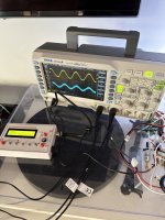
I wanted to run some basic tests on an amplifier I'm building. I have an oscilliscope, and a cheap function generator from Aliexpress.
I hooked it up the way I thought it should be, but I find the signal is pretty noisy.. This is purely from testing as with normal music it sounds perfect, but when hooked up the signal has a hiss in the background and on the scope looks a bit noisy.
1) I connected CH1 oscilloscope probe ground to one RCA ground lug
2) I connected the function generator, via a BNC cable, to the ground lug of the same RCA jack, then ran the function generator signal to the RCA positive lug (which is connected to input connector of the the amplifier channel under test)
3) I connected the second oscilloscope probe to the speaker outputs for the same amplifier.
It works, but signal seems noisy. Anything I should do different?
Attachments
Thank you for your post. I wanted to ask a question on this subject.
1. All my ground are one point.
2. I hook up CH1 to the output of the function generator where it goes into the amp / DUT
3. I hook up CH2 to the output of the DUT.
If I see noise I start to chk from the input and then move thru the DUT to find which component or section is introducing the noise.
Can we have a sticky post on how to use a signal generator to test audio.
I spent 6 months trying to fix my tone control board with a sine wave. LOL.
When in fact I should have been using a square wave.
A stick explaining when and where what function is used to test what.
i.e.
Sine wave, Square wave, White Noise, Pink Noise.
And how the scope is configured to work with each of these.
How do you measure THD ?. etc.
no isolation transformer? i could be wrong but i think there's a ground loop introducing noise.
and not knowing what your amp design is i would be careful where your attaching those probe grounds if the scope is grounded (especially with regard to that speaker output)
and not knowing what your amp design is i would be careful where your attaching those probe grounds if the scope is grounded (especially with regard to that speaker output)
The noise you see on your screen is presumabely rf-noise, i.e. noise above the audio band mostly irrelevant to audio. I use the same scope as you and can confirm that this piece of digigital equipment emits piles of rf - noise into its environment.
Or a sweep sine wave. That IS the classic test for tone controls. You got your HP 200AB sig-gen in one hand, the ACVM in the other (or both in a Transmission Set), and a notebook (paper, not Chrome).trying to fix my tone control board with a sine wave. LOL.
When in fact I should have been using a square wave.
A square tells all but needs insightful interpretation.
Hiss to FFT seems simpler (because the intense computation has become cheap) but is probabilistic and has traps. Actually appropriate for speakers, less so for electronics.
I would think white noise would do a better job at testing a tone control. To see what ranges are being boosted and what are not. Ive started a new thread to discuss testing if you were a deaf tech and had to work on audio.
So on the signal generator - all create noise. Here's my SDG1032X at 1KHz using my DIY audio spectrum analyser I'm building:

You can see the black line being higher than the orange noise floor. Additionally there's more noise in there than just the 1KHz tone (part cables and grounding perhaps). The lift of the noise floor (black vs orange) and the width of the base of the signal are results from a wide range of things. You can even see noise appearing from the synthesis from the SDG towards the right on the black trace.
My point here is that a DDS synthesis but will have additional noise from all the other components, master clock noise, then you have the environmental noise and finally the scope noise.. If you want to measure THD etc then you will need both a clean tone generator and a higher dynamic range that a scope can show (hence my audio analyser).
The fuzz on the lower sine wave is noise on the signal. It looks higher frequency. If you turn the DDS output to zero but leave it connected do you have the same noise? If you remove the probe but short the probe to ground do you get the same amount of noise?
An FFT on the scope will give you a small dynamic range but wide frequency range picture of the signal and noise.
Ideally you want to work out a perfectly noiseless testing strategy.. however that usually doesn't happen without more work:
The DDS is possibly not the best from a noise perspective and that's probably what you're seeing but it's worth checking out that everything is grounded well etc and away from mains cables.
You can see the black line being higher than the orange noise floor. Additionally there's more noise in there than just the 1KHz tone (part cables and grounding perhaps). The lift of the noise floor (black vs orange) and the width of the base of the signal are results from a wide range of things. You can even see noise appearing from the synthesis from the SDG towards the right on the black trace.
My point here is that a DDS synthesis but will have additional noise from all the other components, master clock noise, then you have the environmental noise and finally the scope noise.. If you want to measure THD etc then you will need both a clean tone generator and a higher dynamic range that a scope can show (hence my audio analyser).
The fuzz on the lower sine wave is noise on the signal. It looks higher frequency. If you turn the DDS output to zero but leave it connected do you have the same noise? If you remove the probe but short the probe to ground do you get the same amount of noise?
An FFT on the scope will give you a small dynamic range but wide frequency range picture of the signal and noise.
Ideally you want to work out a perfectly noiseless testing strategy.. however that usually doesn't happen without more work:
- clear the environment (things like LED lights, etc etc)
- use fully shielded connections (ie BNC to BNC rather than scope probes)
- use a DDS for normal testing (they can have better close in jitter statistics compared to an analogue oscillator - narrower base of the fundamental)
- use a low distortion source - such as a -140dB 1KHz tone generator - to make the test tones for THD if you really want better THD figures.
The DDS is possibly not the best from a noise perspective and that's probably what you're seeing but it's worth checking out that everything is grounded well etc and away from mains cables.
Speakers and speaker cables can pick up AM radio. I have seen AM radio signals on the output of an amplifier connected to speakers.
Ed
Ed
Since the AM stations are shut down for years they do no longer interfere with speaker cables. The modern noise sources are LED-lights and smartphones.
If its class d amp then sometimes you can get residual carrier on the output.The noise you see on your screen is presumabely rf-noise, i.e. noise above the audio band mostly irrelevant to audio. I use the same scope as you and can confirm that this piece of digigital equipment emits piles of rf - noise into its environment.
- Home
- Design & Build
- Equipment & Tools
- Basic in-amp testing