PP Slot Loaded Sub with Alpine SWR 12D2

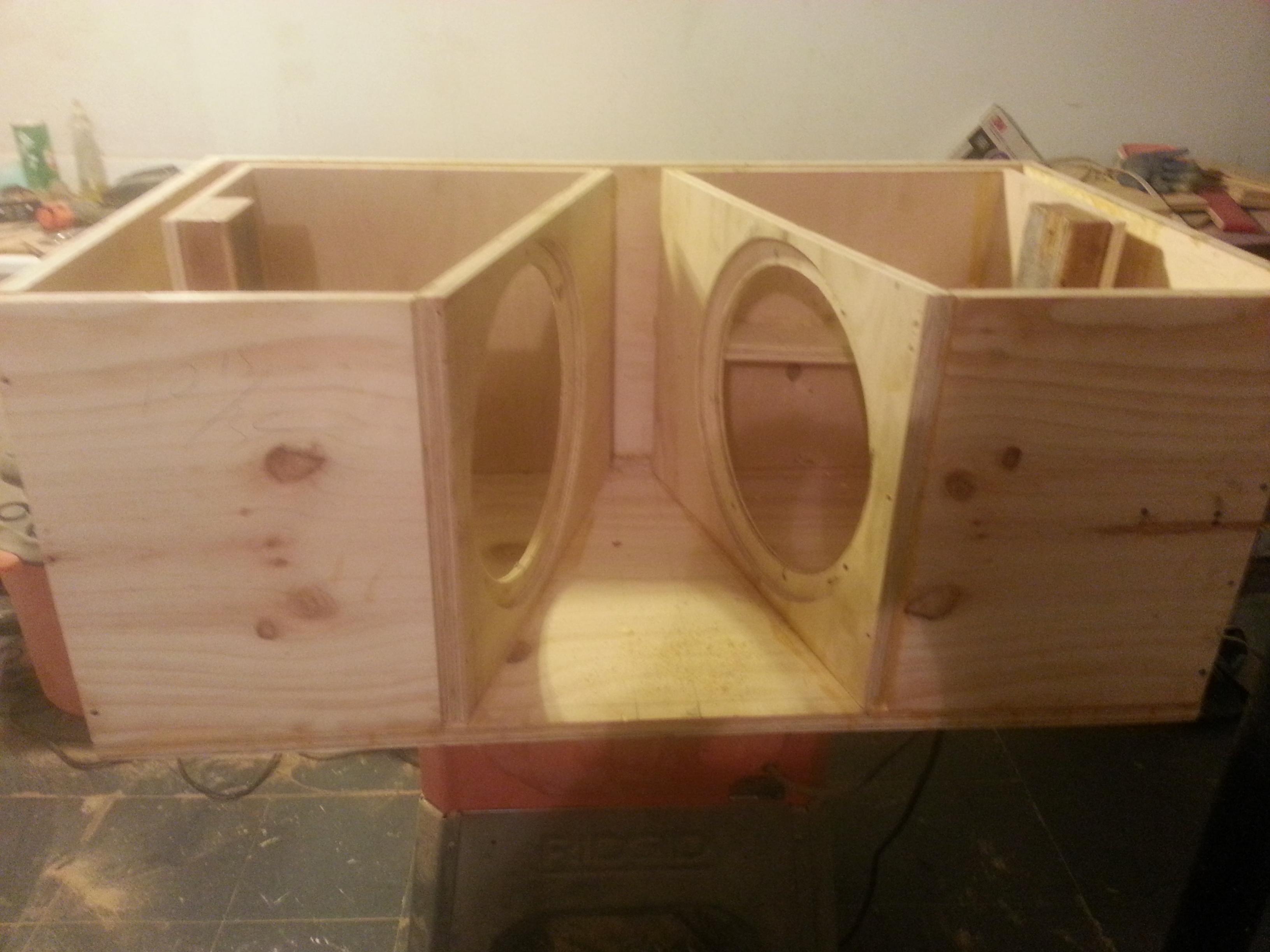
Edit Nov 25: build started.
450570d1416884762-pp-slot-loaded-sub-alpine-swr-12d2-20141124_211830.jpg


I received a request from a member to design a push pull slot loaded sub using the Alpine SWR 12D2 drivers. His goal was to achieve a 37Hz -3dB and to fit in a space constraint of 34in x 15in x 25in, with lots of output from 40Hz to 60Hz.

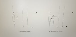
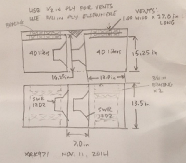
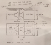
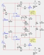
The design I came up with is shown in the sketch below. Each chamber is 40 liters (13.5in tall x 15.25in deep x 12.0in long) with a central slot with dimensions of 7.0in wide x 16.25in deep (not including vents) x 13.5in high, and each chamber having a 0.90in wide x 13.5in tall x 24in long vent from the chamber to the slot. The vents will have two 3/4in braces. It is assumed that 3/4in ply will be used throughout except the vents which can be 1/2in ply. The Alpine SWR 12D2 drivers are dual voice coil deals. Assume the drivers VC's are wired in series for 4ohm nominal, then wire the two drivers in parallel for 2ohms nominal load for the amp. This is a car application so I am assuming 2ohm load is not an issue. Or each side can be driven at 4ohms with stereo amps.

Sketch (note that drawing shows 1.0in wide vents, but should be 0.90in wide to match sims below):

448198d1415763799-pp-slot-loaded-sub-alpine-swr-12d2-ppslsub6-alpine-swr12d2-plan.png


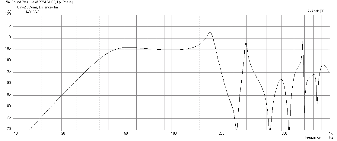
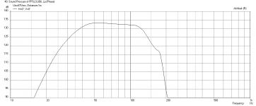
Predicted response at 2.83v and 1m, in 2pi space with no filters:

448193d1415763799-pp-slot-loaded-sub-alpine-swr-12d2-ppslsub6-alpine-swr12d2-freq-1m-2.83v-no-filters.png


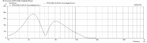
Predicted cone displacement at 67volts and 24Hz -24dB/oct HPF to reach 2kW max thermal rating (RMS) and xmax of 20mm:

448194d1415763799-pp-slot-loaded-sub-alpine-swr-12d2-ppslsub6-alpine-swr12d2-displ-max.png


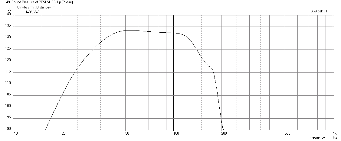
Predicted max SPL at 67volts with above LPF and -24dB/oct HPF at 125Hz is 133dB at 1m:

448195d1415763799-pp-slot-loaded-sub-alpine-swr-12d2-ppslsub6-alpine-swr12d2-freq-1m-max.png


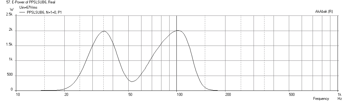
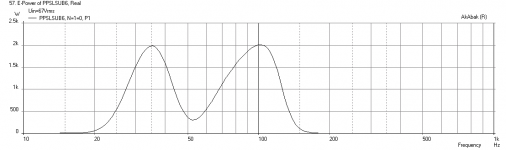
Predicted electrical power input to both drivers (2kW max):

448196d1415763799-pp-slot-loaded-sub-alpine-swr-12d2-ppslsub6-alpine-swr12d2-electrical-power-max.png


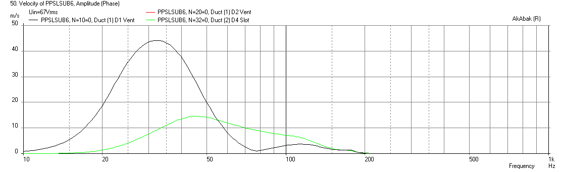
Predicted vent velocities and slot velocity at 67volts (a bit high - so there may be some port compression - the ports are internal and have a slot to reduce turbulence noise if it becomes a problem). A larger vent could be used but that would require a longer than 24in vent which may have other problems like resonances:

448197d1415763799-pp-slot-loaded-sub-alpine-swr-12d2-ppslsub6-alpine-swr12d2-velocity-max.png


In summary, I think that this design should provide plenty of bass down to the requested 37Hz, and with cabin/room gain, probably much deeper.


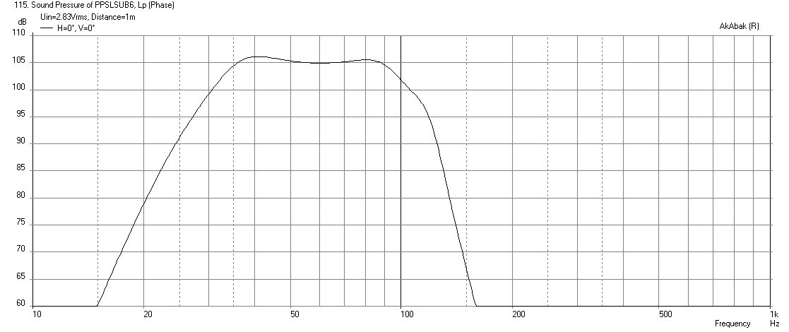
Update Nov 14, 2014 - here is predicted performance with a 12in long x 7in x 8in extension duct at the output slot to bring the bass through a small flip down "ski door" in the back seat of a car.
It achieves 105dB sensitivity at 2.83v and 1m with 32.3Hz (03dB) bass extension:
448505d1415962419-pp-slot-loaded-sub-alpine-swr-12d2-ppslsub6-alpine-swr12d2-freq-1-2.83volts-seat_duct-2-12inch.png


Update Nov 18, 2014: Tb46 was kind enough to provide a drawing of a modified angled waveguide output version below:
449305d1416316312-pp-slot-loaded-sub-alpine-swr-12d2-ppslsub8-alpine-swr12d2-waveguidw-tb46-plan.png


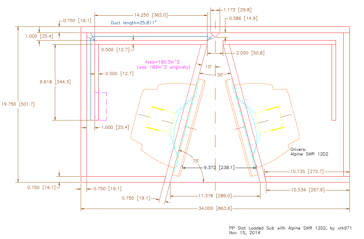
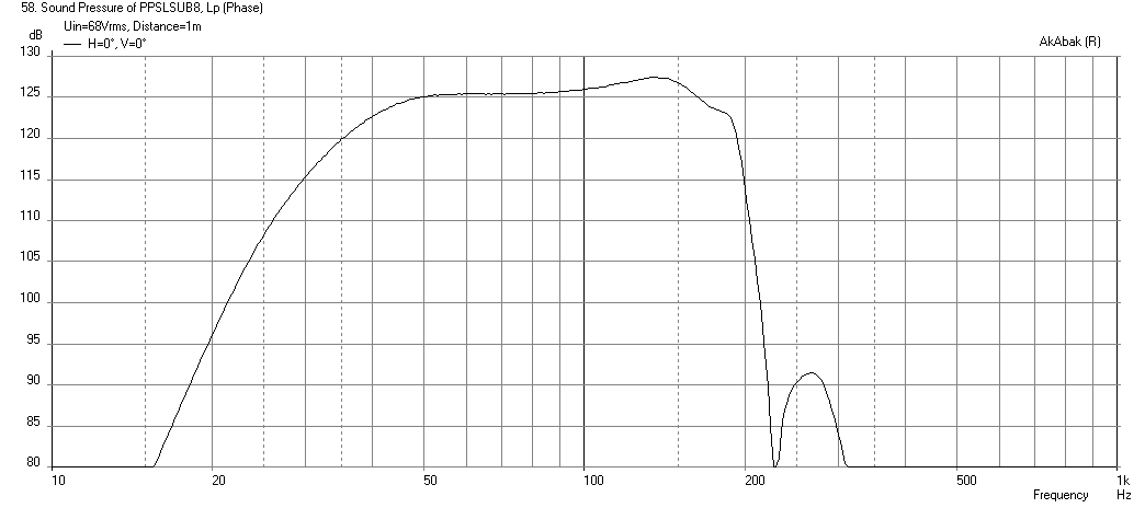
Here is predicted output at 68 volts (with 26in long x 1.0in wide vents) driven to xmax here:
449304d1416315458-pp-slot-loaded-sub-alpine-swr-12d2-ppslsub8-alpine-swr12d2-freq-1m-waveguide-maxspl.png


Update Dec 19, 2014: Another variant of the PP SL bandpass with MCM 55-2421, courtesy Tb46 and lawbiding:

Here is what I call the "Offset SV" Thanks to Tb46 for the great drawings as usual:
http://www.diyaudio.com/forums/attachments/subwoofers/451740d1417487191-pp-slot-loaded-sub-alpine-swr-12d2-mcm_55_2421_ppsl_sv.pdf

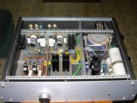
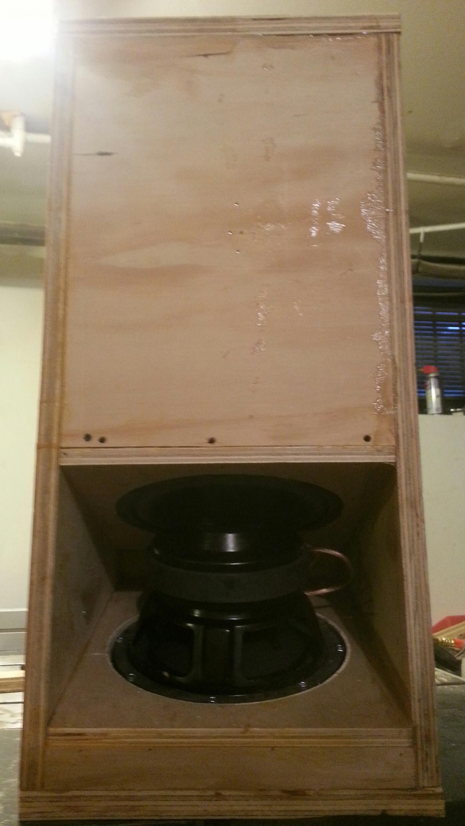
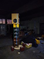
Here is the completed sub by lawbiding:
454578d1418954272-pp-slot-loaded-sub-alpine-swr-12d2-f-pic2.jpg

Attachments

  • PPSLSUB6-Alpine-SWR12D2-Freq-1m-2.83V-no-filters.png
    PPSLSUB6-Alpine-SWR12D2-Freq-1m-2.83V-no-filters.png
    17.7 KB · Views: 4,617
  • PPSLSUB6-Alpine-SWR12D2-Displ-MAX.png
    PPSLSUB6-Alpine-SWR12D2-Displ-MAX.png
    14.8 KB · Views: 2,611
  • PPSLSUB6-Alpine-SWR12D2-Freq-1m-MAX.png
    PPSLSUB6-Alpine-SWR12D2-Freq-1m-MAX.png
    30.8 KB · Views: 2,600
  • PPSLSUB6-Alpine-SWR12D2-Electrical-Power-MAX.png
    PPSLSUB6-Alpine-SWR12D2-Electrical-Power-MAX.png
    13.8 KB · Views: 2,511
  • PPSLSUB6-Alpine-SWR12D2-Velocity-MAX.png
    PPSLSUB6-Alpine-SWR12D2-Velocity-MAX.png
    14.1 KB · Views: 2,525
  • PPSLSUB6-Alpine-SWR12D2-Plan.png
    PPSLSUB6-Alpine-SWR12D2-Plan.png
    340.9 KB · Views: 4,013

Help Identify Mono Blocks

Hi, I need help identifying these two mono blocks. It is very well constructed and seriously heavy for their size. I tried searching on Google but nothing came up. Much appreciated for any info. Thank you.

Attachments

  • s-l1600 (1).jpg
    s-l1600 (1).jpg
    227.5 KB · Views: 108
  • s-l1600 (2).jpg
    s-l1600 (2).jpg
    193.9 KB · Views: 103
  • s-l1600 (3).jpg
    s-l1600 (3).jpg
    207.8 KB · Views: 104
  • s-l1600.jpg
    s-l1600.jpg
    255.3 KB · Views: 101
  • s-l1600 (4).jpg
    s-l1600 (4).jpg
    204.3 KB · Views: 112
  • IMG_8327.jpg
    IMG_8327.jpg
    379.1 KB · Views: 115
  • s-l1600 (5).jpg
    s-l1600 (5).jpg
    140.9 KB · Views: 114

Looking for a 1.4" 100-120° Constant Directivity Horn for a full range cardioid speaker

I'm looking for a constant directivity horn with 100-120° horizontal dispersion for a full range cardioid project. It shouldn't be wider than 460mm and ideally should fit on my 1.4" compression driver. The closest I've found so far is th RCF HF950, which has 90x50°.

At the moment the prototype consists of a 15" on the front, 2x 12" on the sides and a 60x40 horn I had laying around.
Does anybody know of something I could buy that would be a better fit to the low end directivity?

Attachments

  • IMG_20230204_180916.jpg
    IMG_20230204_180916.jpg
    328.2 KB · Views: 150
  • ACAB var4 Directivity (hor).png
    ACAB var4 Directivity (hor).png
    349.1 KB · Views: 155
  • ACAB var4 Directivity (hor)2.png
    ACAB var4 Directivity (hor)2.png
    280.1 KB · Views: 153
  • Like
Reactions: vineethkumar01

2x12V Regulator with Good Precision and High PSRR

PSRR at 1kHz is 114 dB.

Voltage output is +12.000V and -12.000V at all levels of input and at all loads 0-500mA.
Input voltage tested is +/-13.7V to 24V.

There are several other opamps that can be used. And a few common opamps that would not work at all conditions.
For example OPA134 can not fit. Has to be Rail to Rail output.
OPA192 is highly recommended as it has been tested in my simulator and works all the time.

What I do not know is how much noise the output is.
But I do think it is fairly clean or even very clean output.

Attachments

  • Good Precision Regulator 1.jpg
    Good Precision Regulator 1.jpg
    74.4 KB · Views: 271

FS: pair of BMS 4540ND + pair of JBL 6" 90x90 CD waveguide

* SOLD * as of March 15th 2023

I've had the BMS drivers for about 10 years, bought new myself. It's the 8 ohm version. They've been used on and off in a domestic setting, so not a very demanding use for these drivers. In excellent condition. I'm asking for 200$ USD or 275$ CAD for the pair.

I also have a pair of JBL PT-B99HF-1 constant-directivity waveguides, screw-on, 6"x6", 90x90 degrees. I have used these along the above drivers. In excellent condition. I'm asking for 20$ USD or 25$ CAD for the pair.

Items location is province of Québec in Canada. I'm willing to ship just about anywhere.

bms_4540nd_b.JPG
bms_4540nd_a.JPG
jbl_wg.JPG

Types of Speaker Grille

12-e1666418817133.png

As we can see, most speakers have a variety of designs, including the grille, which is important when it covers a large area of the speaker. Generally, there are two types of the speaker grille, which are soft and hard. Sound waves are longitudinal, where the particles are parallel to travel from the direction of sound energy. They can pass through air, liquid, and even solid. Therefore, we are still able to hear even if there are speaker grilles on the speaker. However, do the characteristics of the grilles affect the sounds?

Soft Grilles
Any suitable cloth, fabric, or other equivalent material can be designed as soft grilles, we can even “DIY” or buy grille cloth online. They provide protection from small, lightweight items and may be water-resistant to some extent, but they are prone to be torn or stretched. Aside from longitudinal waves, there are also pressure waves and mechanical waves produced by sound. Therefore, soft grilles are more flexible when they are soft and more free to vibrate synchronously with the waves, resulting in less rattling of the speaker.

Hard Grilles
A variety of materials, including metal, wood, and plastic can form hard grilles. In this case, a board or sheet of material with holes drilled or cut to allow sound to travel through – perforated metal sheets is the common speaker grilles. Perforated metal made of carbon steel, galvanized steel, and aluminum, as well as various plastics like PC, PS, and PET, are among the standard for speaker units and home theatre systems.

Unlike soft grilles, the hard material is not free to move with waves produced. Therefore, the speaker’s output level must be considered when designing the grille. A grille with more holes will allow more sound to pass but will offer less protection from small objects. If there is a huge area of hard materials covering the speaker driver, it will most likely create rattling, impairing the experience, and sound quality, which ultimately damages the speaker.

If you would like to know more, kindly visit our website: Speaker Grille Malaysia
  • Like
Reactions: gregulator

SMD Code (ON Semi) RRT P2D and RSB P1D (RS8 P1D)

Hi,

can someone help me to figure out what transistors this are ? They are part of an inputstage - I have tried to search on smd code lookup websites but I couldn't find them. Case is SOT-223 or SOT-89

Could it be
PZTA92T1G and PZTA42T1G ?
I have seen them extensively used in a Dan D'agostino amp.

https://parttimeaudiophile.com/wp-content/uploads/2022/11/Dag250MXV_Small-23.jpg

Improving acoustics in the concrete bunker

I thought I would make a thread about improving the acoustics in my 'concrete bunker' living room. I'm a total novice when it comes to room treatment, so I hope some members will chime in to guide me a bit.
Background:
We moved to this apartment, over a year ago, and the acoustics of this concrete bunker scared me, and I have been wanting to improve them, because listening in this room was no pleasure. I have tried some small mods building some really simple absorbers from some towels in a wooden frame covered with some fabric. I placed those at the front wall behind the speakers, and it did not do very much. I also filled the underside of the sofa with abt 30 IKEA pillows, and that actually seem to help a bit, it became more comfortable to sit in the 'sofa corner' watching TV and also having music on in the background. Main listening position also improved a bit, subjectively. I did not measure before/after.
I also have some thicker type of curtains in the windows behind the listening position, and also covering the terrace door (with a window in the door), thick rug on the floor etc.

There are a lot of limitations/restrictions on the layout possible, the amount of treatment that can be accepted visually, and also the space available for absorbers/traps. Basically the layout is what it is, it was the only way I could fit the stuff due to doors, effective use of the space etc.
So this is the basic layout with room dimensions:

Livingroom dimensions w furniture layout.jpg


The height of the speakers is the height of the woofers.

I did some measurements with REW today. I attached the complete set of measurements, but here is an example of the listening position with both main speakers playing.
listening pos.jpg


I also took some measurements in the corners and on the side walls, where I'm thinking it would be possible to place some kind of bass traps, thinking it would show if a certain position is better for treating a specific room mode. Usable corners are RL and the front wall corners, even if there are space limitations.

Here is a panorama-shot, taken standing by the right side wall, to give a better idea of the situation.
20221206_170153.jpg


I will leave it at that in this first post, and continue with some Ideas I have, and some material I have stocked for this.

Attachments

Capacitor Question

I’m rebuilding an amp for myself that had all power supply fets blown almost half the outputs ,drivers , and gate resistors .

My question is they are using Sam young caps in this amp for the rail caps and filter caps .

I know it’s been discussed a lot . Loke why do people replace caps for no reason .

My question is should I replace these Sam young caps in this amp to a better quality cap?

Just wondering if the amp will be more reliable or any benefit to replacing these Chinese caps with better quality?

Tablet/phone remote control of Tidal on PC

Apparently, it’s “coming soon”. Does anyone know when? Having to use a mouse and laptop connected to a TV was already very tired when Tidal added partial remote control capability a few months ago.

I am sick of waiting, and of the annoyance of a sub par user interface when compared to Spotify. Yes, Tidal sounds better, but soon Spotify will have a HiFi version similar to Tidal’s. At that point, why would anyone bother with Tidal if it still doesn’t have the same functionality? The clock is ticking....

Any news that anyone might have would be much appreciated.

Enclosure for Tang Band w5-2143

Hi, I order 2 of these speakers ,I read very good reviews for them ,and now I want to choose the best enclosures for them. What is the most appropriate construction closed box ,ported box,tl ,ob or horn ,what is the best enclosure .Which is the best box of which I will get maximum low frequencies with low times of group delays and at the same time preserve beautiful mid and high frequencies. Mostly listening to vocal jazz and pop.
Thanks 🙂

China BPR56 ceramic 5W power resistors

Dear fellow DIYers,

I like to show you the inside of a cracked open 5W power resistor I bought on Aliexpress.
Those resistors are sold as "BPR56" 5W non-inductive power resistors and cost roughly 0.30€ p.p. including shipping so I was hoping they could be somewhat well made.
Needless to say I accidentally destroyed one of them during measurements and cracked it open to see what is inside.

What I found inside looks rather disappointing:
Lots of cement filler and the actual resistor looks like it can handle 1W maximum.
Also, the resistor is wire wound, thus not low inductance.

Here is the picture:
China_5W_BPR56_ceramic_resistor.jpg


What do you think?

Further progress on my RCD965BX upgrading using Burson Audio V6 Vivid discrete op-amps.

Warning : Little review ahead : sorry if this is naughty, but I promised BA I'd review them.

Following my posts about what I could do to get the best out of my extremely cheap Rotel RCD965BX, but still using just my Denon AV amp and my ageing but at least HiFi Monitor 3 speakers, I got a PM from Burson Audio asking if I'd like to try putting a couple of their Discrete V6 op-amp substitutes into the O/P stage. I said, surprise surprise, yes please, and chose the vivid models. I'm not a youtube content creator, and I'm not on many audio forums, and I certainly don't write reviews normally, but I'm hoping that BA will be happy to read my little review here, because at the moment (after an hour or so burning in) they're at the top of my christmas card list.

I was actually a bit sceptical at first - I knew from my past that opamps can improve things (I'd swapped something somewhere I remembered) but I thought I'd pretty much got as far as I was going to get with my non-HiFi setup - and TBH, I was pretty happy with what I was listening to from the CDs; since I remembered them being pretty harsh when they first came out, and I stuck to my PT Too/SME309/Lyra Clavis analogue setup until marriage and house moves put real HiFi at the back of the queue. For 30 years !!. Anyway, I'd started listening to CDs again, and bought the Rotel on a whim - and realised that actually, even stock, it was pretty good, and was making my denon AV amp even sound pretty good - but better was calling, at £20 it didn;t matter if I blew it up !!

TL😀R - they're brilliant. I have never heard my HiFi (even in the current case a non-HiFi) sound so interesting - I've heard instruments not heard before, voices change to whispers and back again, and words don't get lost in the noise - I can hear a band, rather than just some nicely presented music from good speakers.

Wrapping up, I can only praise them as being a very very cost effective uograde, even if you have to buy them; From my description, you can see my other components aren't brilliant, but I'm really wondering of Linn were right all along - maybe the source is the most important component - especially at the lower end of cost range ?

x-over redo : Cost vs. Effect

When you look at the x-overs in many mid level oem speakers, it seems that relatively cheap parts are used. Like electrolytic caps, steel core inductors even in the hi pass, sand cast resistors etc. Would remaking the x-over with quality poly caps, air core low dcr inductors , non inductive resistors, be worth the effort and $$$$ . I know this is subjective , dependant on how well the speaker already sounded. Case in point the Infinity IL40

Fixing up Some Old Acousti-Craft Speakers

Stepping back into a project I started a few years ago, but set aside as I became busy with other things. Here’s what I have. A pair of Acousti-Craft speakers that I got from my grandfather. I replaced the drivers that were in there temporarily with GRS 8FR-8 full range. I’m looking to convert these to something that sounds much better. The original TechTalk thread I started for this project can be found here. I’m looking to get some thoughts from the DIYAudio community as well.

I’d like to redo the driver setup on these so that they work about as well as they can for the purpose of 90% TV and movies 10% music. Positioning two to three meters from listeners and speaker centers about 5 to 8 feet apart. 6 to 8 inches off the wall and pointing straight ahead, no toe-in. Good imaging and soundstage would be desired for that immersive movie experience. It will mostly just be me using these, but I would like the sweet spot to be fairly wide if possible for times that it’s not just me. I’d like these to reach down into the mid to low 30s so I won’t have to add a sub.

I’ve been doing a lot of research on what I can do with these and keep coming back to a 2-way. I’m guessing any full range options would beam too heavily for the positioning I will be using these at and also not reach the low range I would like. 3-way is increased cost and crossover complexity with potentially more extensive cabinet mods than I am wanting to do.

As pointed out to me in the TechTalk thread, the RS225-8 is a great match for this cabinet. From what I’ve read, I’ll likely be very happy with the performance of it, but if anyone feels I should consider something else, let me know.

Tweeters have been more difficult. Top of my list currently are the Wavecor TW030WA 11/12, either of the Peerless corundum or one of the SB Acoustics SB26 variants with perhaps one of the Soma Sonus waveguides. This is probably the biggest thing I need help deciding on now. Anyone have any opinions on what tweeters out there would work best for, hopefully, getting close to my goals while crossing low enough for the RS225?

Attached is an FBX of a model I created for visualizing potential cabinet modifications. It might be useful if someone has recommendations on adding bracing or wants a better idea of what I’m working with. Still trying to decide if I want to preserve the original look of the cabinets or make some minor changes such as getting rid of the grill cloth and having a more decorative front baffle with exposed drivers.

Attachments

  • AcousticraftSpeaker_001.zip
    AcousticraftSpeaker_001.zip
    593.9 KB · Views: 55
  • Acoust-Craft_RS225_TW030WA11_Original_Blend.jpg
    Acoust-Craft_RS225_TW030WA11_Original_Blend.jpg
    37.3 KB · Views: 77
  • Acoust-Craft_RS225_TW030WA11_Stripes.jpg
    Acoust-Craft_RS225_TW030WA11_Stripes.jpg
    39.8 KB · Views: 64

I need help with new crossover

Hi all. I built crossovers 3 years ago for my speakers out of stuff I had laying around. They work but I think they could be much better.

So I have Heil AMT 4 ohms for tweeters, JBL 2441 16 ohm compression driver on 300hz Edgarhorns, and Lambda TD15 8 OHM woofers. I built 1st order xovers. I cross over at 700hz to the horns and 4khz to the Heil.

So what type xover do you think would be the best xover???

Attachments

  • 20160605_111936.jpg
    20160605_111936.jpg
    36.7 KB · Views: 357

Denon AVR-5800 popping sound from one channel when muting or channel turns on/off.

Hi have a denon AVR-5800 that works great. However, the left surround A-B speaker pops when I mute the receiver; or when i change the inputs. I think when the speaker output is turned on/off by the amp - it triggers the pop. I tried the same speaker on the right surround channel - and no pop.

I do see a service bulletin on the pre-amp output that suggests changing the muting transistors. But this pop is on the amplified output. Any ideas? Also - I downloaded a service manual for the AVR-5800 - but there are no circuit diagrams in the manual. Is there a different source to get circuit diagrams?

Square inductors will they work.

So turns out one of my friends has a company that makes transformers.
I was at his factory the other day and I noticed they had a lot of plastic bobbins and machines that could wind any number of turns I like in any gauge I like. But only on these square bobbins.
The only catch here the bobbins are all square plastic. It also looks like once the bobbin is wound and coated with epoxy you can cut out the plastic I don't see the plastic being different from an air core.
Is there any reason why all inductors are round ?. Can I use these square bobbins / Square inductors ?.

Audio Note Kits L1 Build...

Received my EL84 tube integrated L1 kit from Brian Smith of Audio Note Kits Canada this week--only regret is the lack of time to build. Nevertheless, wow, what a nice package! All high quality parts very well packaged and well laid out. Can't wait to get to the listening point.

For now, I have populated all the resistors on the 3 mm PC board.

Thought you all DIYers would like to look over my shoulder as I build it.

Attachments

  • DSCF3251.JPG
    DSCF3251.JPG
    345.5 KB · Views: 2,974
  • DSCF3264.jpg
    DSCF3264.jpg
    396.9 KB · Views: 2,900

For Sale Koss ESP 9 experimental delight. 4 energizers two 'pones 1 box

Hi,
I have a collection of Koss ESP 9 energizers (E9). There are four in all. All work and one is in very good condition as it was boxed for most of it's life. There is one original box that the best E9 was in and a fully functional ESP 9 'phone that is not part of that set, but from another set. I have it's energizer in this group, too. That energizer is in OK condition and 2 energizers are a little rough.
There is also a pair of rare ESP 8 'phones that worked when they went into the box many years ago, but they now have one driver out. I simply don't understand why the ESP 8's do not work? Also there is an original Owners Manual for the ESP 9.
Both 'phones had original foam that turned into some kind of muck. I carefully cleaned it out and put new foam in. The working set sounds good even after all the years. My vision is too poor to do much in the way of mods, so I'll let them go.
I can send details and photos to serious inquiries. A serious inquiry means you accept that the firm price is 300 plus shipping for all.

An experimenters delight, but you can simply listen to a working pair while you experiment.

Restoring dad's Presto turntable

Well, I swung by my Dad's house and did some digging in the attic. I've pulled out his Presto turntable as a new project.

This will be more of a restoration than a heavy modification. There are a lot of memories tied up in this. I remember it being in the living room system for years (I remember it from about 1960 to about 1975 when he replaced it with a used Weathers turntable). This is the turntable my sister wore out her mono copy of Rubber Soul on.

Dad made the base out of some scrap pine. The main motor plate is carved out of a piece of about 3/16ths thick scrap iron (there are a few extra holes in it from a previous ussage). The Velvet Touch tonearm is the best feature, and should clean up pretty nicely.

I think I will clean, sand, prime and paint the motor plate. I'll probably sand and stain the case and possibly add some handball feet to give it a bit of suspension.

It will be built up a part of a mono only system for LP's and 78's. I also picked up a small collection of GE cartridges, which should match the tonearm nicely.

Also picked up a nice little Heathkit amp and his old Triplet meter.

Here are the before pictures!

David S.

Attachments

  • IMGP3937sm.jpg
    IMGP3937sm.jpg
    211.9 KB · Views: 455
  • IMGP3938sm.jpg
    IMGP3938sm.jpg
    215.7 KB · Views: 394
  • IMGP3939sm.jpg
    IMGP3939sm.jpg
    206.6 KB · Views: 383
  • IMGP3940sm.jpg
    IMGP3940sm.jpg
    209.8 KB · Views: 357
  • IMGP3941sm.jpg
    IMGP3941sm.jpg
    153.5 KB · Views: 356
  • IMGP3942sm.jpg
    IMGP3942sm.jpg
    244.7 KB · Views: 262
  • IMGP3943sm.jpg
    IMGP3943sm.jpg
    218.9 KB · Views: 249
  • IMGP3945sm.jpg
    IMGP3945sm.jpg
    185.4 KB · Views: 269
  • IMGP3947sm.jpg
    IMGP3947sm.jpg
    177.5 KB · Views: 266

Running a passive crossover externally from a distance?

I just rewired some stage monitors for biamp operation. I didn't want to add the switch necessary to be able to operate them passively or in biamp mode. But it occurred to me that if I ran the signal into the old crossover at the amplifiers, and then connected the crossover to the four conductor cable that runs the speaker, boom, I'm back in passive mode.

It's a little weird, but I'm only preparing for it just in case an amp or crossover fails. I'm doing live sound so I've gotta deal with things like that on the spot.

I was wondering how much it will affect the sound having a larger resistance from the longer cable run post crossover. I do run 14 gauge cables so in the crossover would probably be 20 feet from the speaker.

I'm hoping it makes no difference at all but I figured I'd ask.

Soundstream Reference 500 Driver Board

Hi guys, does anyone have a driver board for a Soundstream Reference 500 they would like to sell? I’ve replaced most of the active components and repaired several broken traces but the board still won’t work. I’ve done some extensive repairs to the main board and got the amp working, but one channel won’t produce sound. I swapped the driver boards from one side to the other and the previous non-working channel now plays fine so I know it’s the board. Thanks.

Attachments

  • 5A48FCF2-E86E-423A-8371-4D3E61D60798.jpg
    5A48FCF2-E86E-423A-8371-4D3E61D60798.jpg
    968.3 KB · Views: 326

DBX 202C gold cans por sale!

Hi everyone!
I am selling these precious VCAs, disassembled from a JH636 MCI to which I have deactivated the automation. Even today there are companies that imitate them, but their sweet harmonic distortion cannot be imitated. Ideal for clones of the famous SSL 4000 bus compressor.
I have 20 units, all of them checked and in good working order.
Price €190/pair.
Shipping costs:
Spain: €6
Europe: €20
America: €30
Asia: €30
Australia: €40
The shipment is made as registered letter. If you want another type of shipping, please consult!

Attachments

  • DBX 202C parea.jpg
    DBX 202C parea.jpg
    107.9 KB · Views: 210

Through hole replacement from one side?

My amp has a board that is a royal pita to remove, literally a 2 hour job and i need to replace one slightly burnt resistor.. i was thinking that i could snip the offending resistor out leaving as much of the legs as possible, and solder the new one (quickly!) To the leads of the old one..

If i ever do pull the board again, id plan on a proper replacement...

Hate doing things that make me feel like im doing a hack job, figured I'd check here to see if this is generally an accepted repair method..

Modern TV Antenna and interference?

I had put my five year old rabbit ears on my amplifier and seems it's well done. Started shopping for a new TV antenna, reading there are ones that claim to have 10X the signal range, going to hundreds of miles. As little as l like broadcast TV, it's still nice to have - to keep my better half happy I need to pay for PBS.
More important is keeping RFI to a minimum... and don't even know if the frequency used now makes a difference. Have plenty of tubes in various stages. Many alligator clip pairs to keep looking for most quiet background.
All TV antennae have amps built in?
Cheers!

For Sale Sony C-800G 2000s Black

Selling this Sony C-800G (microphone) and the AC-MC800G power supply. I only used this microphone for occasional stereo pair recordings as I own two. I'm doing less live-band recording and decided to part with the microphone. It has been extremely well taken care of.

If you're looking at this microphone, you must already know how well this mic performs.

I'd prefer local pickup, but will ship also with FedEx or UPS. safely.

Price : $4600
Shipping cost : $120

Attachments

  • cgzu326zqacnjbqt0ugi.jpg
    cgzu326zqacnjbqt0ugi.jpg
    222.8 KB · Views: 189
  • jcwxbyk2fiqva3nnyswn.jpg
    jcwxbyk2fiqva3nnyswn.jpg
    321.3 KB · Views: 144
  • bqpyeeml459opx3njc9m.jpg
    bqpyeeml459opx3njc9m.jpg
    223.4 KB · Views: 134
  • k30jujormsmxdtdvvwu1.jpg
    k30jujormsmxdtdvvwu1.jpg
    237.9 KB · Views: 155
  • q4jh94kpsmhuttcdvku4.jpg
    q4jh94kpsmhuttcdvku4.jpg
    360.7 KB · Views: 115
  • Capture d’écran 2022-12-27 104129.png
    Capture d’écran 2022-12-27 104129.png
    234.6 KB · Views: 120
  • Capture d’écran 2022-12-27 104136.png
    Capture d’écran 2022-12-27 104136.png
    228.5 KB · Views: 117
  • Capture d’écran 2022-12-27 104144.png
    Capture d’écran 2022-12-27 104144.png
    302.5 KB · Views: 120
  • Capture d’écran 2022-12-27 104151.png
    Capture d’écran 2022-12-27 104151.png
    304 KB · Views: 120
  • Capture d’écran 2022-12-27 104159.png
    Capture d’écran 2022-12-27 104159.png
    461.1 KB · Views: 111
  • Capture d’écran 2022-12-27 104209.png
    Capture d’écran 2022-12-27 104209.png
    196 KB · Views: 107

Extending (relocating) MOSFET from amp board

I got a couple old Dayton 250 watt sub plate amps that have given lots of issues over the years w/ the amp section.

Finally tired of repairing the amp, I decided to purchase a couple cheap class d amp boards online and will re-use the xover, preamp, power supply in the plate amps and install these little class d amps in place.

Here is the exact ones I purchased: https://articulo.mercadolibre.com.mx/MLM-1368826029-modulo-amplificador-clase-d-irs2092-500w-_JM

Nothing special, these are the dime-a-dozen IRS2092 boards available all over from ebay, ali express and other sites.

The problem: These boards have two MOSFETSs mounted (to the PCB) under a tiny heatsink w/ fan. My plate amps have the normal external heatsink with interior space for mounting the active devices.

What I am proposing to do:

1) Remove the heatsink and clip the MOSFETS from the board
2) Add 2-3 inch long extension leads to the MOSFETS and re-attach (the new leads) to the amp board.
3) Mount the MOSFETS directly to the heatsink as the original amp was. I have insulators and mounting pads to ensure they are electrically isolated.

The question: would there be any issue with extending the leads like this? Do the MOSFETS have to be close to the board, or can "extending the leads" be safely done? I hear stories of capacitance issues and other similar issues with MOSFETS.

Thanks!

Voltage selector application and modification

Hello,

I've bought a bunch of voltage selectors made by Schurter, Switzerland, for less money. It allows for selecting one out of six possible mains voltages, given the mains transformer features a four section primary: A pair of ~100 V windings and another pair of ~20V windings. For details see the attached datasheet, please.

What voltages would you chose for the individual winding sections to cover as many actual mains voltages as possible? My idea would be two 110V and two 10V windings, allowing for 110-120-130-220-230-240V mains voltage. Is this appropriate and versatile enough?

As said above, the switches were from surplus, hence relativly cheap. The reason for this most probably was the writing: Mine are part # 0033.3501, the fist one in the list, and allow for 110-130-150-220-240-260 V when connected to a 2x110V+2x20V transformer, which isn't very useful. So, after having defined appropriate voltages (see above), I think to have someone make donut shaped stickers that I may stick onto the switches. As the angle between each pair of positions is 30°, I need to put the voltage numbers in a circular arrangement. Which CAD software is useful for this purpose?

TIA and best regards!

Attachments

Dual supply SMPS - wrong purchase?

Hi,

I'm looking to upgrade the power supply for my DIY amp. I've currently hooked it upto a 24V wall wart supply. I've got a +/-40V SMPS supply with 3 output connections : V+, V- and GND.

My amp has 2 power input connections : V+ and GND. The amp manufacturer recommends a single supply SMPS.

The amp requires 24V to 51V. I have no electronics background, and reading how SMPS psu's work is hard going. But it looks to me as if I can't use the +/- SMPS supply.

Any ideas/suggestions, or do I bite the bullet and buy a single supply SMPS?

Thanks

Placing autotransformer in crossover

Hey guys,
actually I'm building a two way speaker and I wanted to attenuate the tweeter using an old school autotransformer. first of all I located it after tweeter HPF but when I measured all taps frequency response I felt something is wrong. Autotransformer should not change the frequency response like this so I removed it and connected it before the HPF and the frequency response seems correct.
I want someone tip me off where is the right place to connect autotransformer in a XO network and if someone can explain the reason of this frequency response it would be great. (I suppose autotransformer after a LR2 filter would we a second inductor in parallel with the first inductor)

attachment.php

-------------------
attachment.php

Attachments

  • 01.png
    01.png
    111 KB · Views: 4,719
  • 02.png
    02.png
    97.5 KB · Views: 3,705

Fostex FF105WK/FF85WK - better than FE83NV2/FE103NV2 (or better replacement for obsolete FE87E/FE83EN/FE103E/FE103EN) ?

Any experiences concerning compare the sound character in listening tests ?
Thanks for comments.

FF-series, only one datasheet for all:
https://www.fostexinternational.com/docs/speaker_components/pdf/ffwk.pdf
https://www.diyaudio.com/community/...k-suitable-for-tv-multimedia-speakers.379251/
https://www.diyaudio.com/community/...o-alpair-6p-tested-against-each-other.242917/
https://www.diyaudio.com/community/threads/fostex-ff105wk-drivers.200711/
https://www.diyaudio.com/community/threads/fostex-ff105wk-experiments.248666/

Examples, FF series:
https://www.diyaudio.com/community/...a-ported-boxes-does-it-get-any-better.364188/
https://www.diyaudio.com/community/threads/i-made-a-small-waw-with-fostex-ff85wk.386376/
https://www.diyaudio.com/community/threads/thoughts-and-opinions-about-fostex-ff85wk.228260/
https://linhkienloadai.vn/products/ff85wk-mau-thung-micro-fonken
https://www.audio-talk.co.uk/phpBB2/viewtopic.php?t=4461
https://www.stereonet.com/forums/topic/510502-fostex-ff105wk-with-fop1000h-enclosures/

FE-series (new and obsolete versions), datasheets:
https://www.fostexinternational.com/docs/speaker_components/pdf/FE83NV2.pdf
https://www.fostexinternational.com/docs/speaker_components/pdf/FE103NV2.pdf
https://www.fostexinternational.com/docs/speaker_components/pdf/fe87erev2.pdf
https://www.fostexinternational.com/docs/speaker_components/pdf/FE83En.pdf
https://www.fostexinternational.com/docs/speaker_components/pdf/fe103erev2.pdf
https://www.fostexinternational.com/docs/speaker_components/pdf/FE103En.pdf

TV-sound streaming with AirPlay: is there a delay?

What I try to do
I want to make a setup to stream the audio signal from my TV, to wireless speakers. The picture below shows my 1st attempt. In this setup I connected an Arylic S10 to the TV, to convert the TV-audio signal to a stream. Both (active) speakers have an Arylic Up2Stream Mini, as receiver for the audio signal from the TV. The two speakers are grouped as a stereo set.

Issue
In this setup, there is a delay between the audio and the image on the TV. So to speak; if you see someone talking on the TV, the words come 2 seconds later.

What I found out
The Arylic products I used in my 1st setup are based on the Linkplay A31 chipset. As soon as they are grouped, they delay the audio signal coming through for buffering and synching.
Somewhere I read that AirPlay2 does not create a delay in the audio stream, even not when grouped.

My questions
So now I am thinking over if it makes sense to look for a TV, that supports AirPlay2 for streaming audio to wireless speakers.
For the speakers I am thinking to change from the Linkplay A31, to the Linkplay A98. This chipset supports AirPlay2. And it is integrated in the modules by CloudYX, for instance the CL-98BW.

  1. Does anyone have experience with streaming audio from a TV, with AirPlay(2), to wireless speakers?
  2. Does anyone have experience with the Linkplay A98 chipset, or the CloudYX CL-98BW?

  • 1674314216789.png

Unorthodox HV Supply Thoughts

I need to come up with a moderate-level HV supply for a small 1-watt 1-tube audio test/signal tracing amp. I do not have any spare tube PT's for this project, but I do have a couple of 120V to 12V center tap PT's. I'm planning on using a 12V 2A center-tap filament transformer winding to power the full secondary of smaller 120V to 12V/40mA transformer for the HV supply. I'll also be using one side of the filament transformer's secondary to power a 6AV8A tube filament. I'd appreciate thoughts on the feasibility of this idea as opposed to using a voltage multiplier scheme. Thanks for any and all input!!

Here's a rough schematic of what I mean.

2-12V-xformer-HV-supply.jpg

Continuous Monitoring of Household Mains Voltage

Hello All,
A few months ago, I started experimenting with inexpensive ways to monitor fluctuations in household power line voltage.

I started by building a test jig consisting of an isolation/step-down transformer (Stancor P-8363), and a voltage divider. The voltage divider consisted of a 302K and 2.67K 1W resistors. I also added a 200Ω 25W resistor to add a load for the secondary. That arrangement gave me a step-down ration of 968.8:1, so a nominal 120VAC to the primary would result in about 125mVAC to monitor.

Next, I looked around for ways to continuously record that voltage. Analog Devices makes a True RMS-to-DC Converter chip (AD736), and even more interesting, an Evaluation Board all stuffed and ready to plug-and-play. Not inexpensive, but exactly what I was looking for. I happened to have in the closet an old strip chart recorder which I pulled out and cleaned up. With all the parts in hand, I lashed-up a test setup as shown in the first attachment.

Attachment 2 shows a portion of a 19-hour recording. The entire recording looks just like this. Visually, the average was about 60 chart lines or 120VAC. The highest voltage recorded occurred around 9:45PM and was 123VAC. The lowest voltage recorded occurred around 6:30AM and was 118VAC. The negative going spikes throughout the recording are probably utilities like sump pump, well pump, furnace, etc., turning on. The largest one I could find had an amplitude of 2.8VAC.

All told, this looks like pretty calm line voltage, as might be expected, since I am located in a rural area. I would be interested to learn what others think.

This experiment says nothing about high frequency hash that might be on the line. While I have the jig set up, I will put the OScope on it and also try to look at the distortion spectrum.

Cheers,
ceulrich

Attachments

  • 1 - Test Setup.png
    1 - Test Setup.png
    73.4 KB · Views: 222
  • 2 - Chart.pdf
    2 - Chart.pdf
    1.3 MB · Views: 206

Digital re-clocking

For the digital re-clocking gurus.


1: If I have a dac that's been measured to have itself 5ppm of jitter on it's outputs. What happens to that if I feed it 200ppm of jitter from a source, does it stay at 5ppm.
2: Then if I insert a regarded re-clocker that said to have 0ppm, and insert that between the 200ppm source and the 5ppm dac, what come out of the dac then????

Cheers George

For Sale Whammy (Waynes Headphone Amp Must Make Yourself) Headphone Amplifier For Sale

I have a WHAMMY headphone amp for sale - fully assembled, tested, housed in a Hammond enclosure. I built a couple of these last month and only use one so I'm looking for a good home for the other. Pictures below show the details. Quality parts and solder used throughout, PCB cleaned of flux post build. Sounds fantastic. Power chord included.

Located in San Diego area. Local pickup or will post. Asking $400 + PP

PXL_20220702_052913318.MP_2.jpgPXL_20220606_053928872.jpgPXL_20220606_053851043.jpgPXL_20220606_053855098.jpgPXL_20220606_053909325.jpgPXL_20220606_053919185.jpgPXL_20220606_053906643.jpgPXL_20220702_052724217_2.jpg


See the original DIYAudio thread and build guide for more details:
https://www.diyaudio.com/community/threads/whammy-pass-diy-headphone-amp-guide.317803/
https://guides.diyaudio.com/Guide/WHAMMY+headphone+amplifier/3?lang=en

PSU resistor

I'm running two of pictured supplies in double mono configuration for my class AB amp. I have fried a resistor R1 on one of them during a mounting, probing hiccup. It's value is ~16k5 on a good board.
Question: what's the purpose of this resistor? Spliting the ground between two poles? Can it be replaced with more common 15K or 18k values?

IMG_5038.jpg

Attachments

  • IMG_5040.jpg
    IMG_5040.jpg
    263.9 KB · Views: 102

Klipsch Quartet crossover update

Hey all,

I have a pair of Klipsch Quartets that haven't been used in a few years.
Previously I replaced the crossover caps and tweeter diaphragm to Ti from Bob Crites.

While the brochure lists a high sensitivity number, as far as I know the impedance/phase plots of these Klipsch are pretty ugly.
I have a few single ended tube amps (5W-10W) and instead of building another speaker (full ranger, OB or what not) I was thinking of making a new crossover, one that has a friendlier impedance for single-ended amps.

I have ARTA/LIMP and have used it only to test amps but never to test a speaker/crossover.
I don't have any experience with this so would appreciate help in where to start, unless this isn't a good idea.
Thoughts?

Attachments

  • 2019-10-21 17.56.11.jpg
    2019-10-21 17.56.11.jpg
    430.9 KB · Views: 147
  • R4s1zUkn.png
    R4s1zUkn.png
    563.4 KB · Views: 132
  • Quartet-Brochure.pdf
    Quartet-Brochure.pdf
    749.7 KB · Views: 219

can't find source of hum - Broken Akai AM 2600

Hi there,

I've been trying to fix this Akai AM2600 for a while, but I just can't seem to figure out the issue.
The thing is, the amp was run with blown fuses for a while (by inexperienced people), so all the power going to the speakers came from the preamplfification/volume control circuitry.
Ever since then the amp has been humming at 50hz

I can turn down the volume using the volume knob. With the knob all the way to the left (off) the humming is gone.
I've drawn the path the audio takes from the aux input, to the volume knob PCB in red.
The lines marked with a green 'X' are lines that I have disconnected. Whenever these lines are disconnected, the humming is completely gone. Meaning it has to come from either the Equalizer PC Board (weird name, it doesn't equalize?) or the Tape PC Board.
The audio signal doesn't pass through any active circuitry on these PCB's however, so I've been left wondering where the hum could come from
I've also disconnected the lines with the blue 'X', this didn't change anything however.

Does anyone have ANY clue as to wat might be going on here?

Thanks in advance!

PS. I've also attached the service manual

Audio Path.png

Attachments

Soundlab ESL Repair Questions

Hello all
I recently acquired some SL UIPX speakers. They sounded great for about an hour and then I noticed some distortion and ugly noises that wouldn’t go away. I switched power supplies and it stayed with the panel. So definitely a panel issue. It only distorts at certain midrange frequencies.

I removed the panel and then the speaker cloth and got a good look. Thankfully I don’t see a ripped membrane but I do see a lot of wrinkling in the Mylar but only from the back. I attached a photo from the back.

The weird thing is it seems to have two membranes. If you look at the layers i think they go like this starting from the front
1) Major vertical and horizontal structural pieces in around a 4” by 8” grid.
2) Finer grid of squares approx. 1” square
3)Wires running vertically that appear to be attached the the finer grid
4) Mylar with a black coating on
5) Clear Mylar
6) Wires running vertically that appear to be attached the the finer grid
7) Finer grid squares approx. 1” square
8) Major vertical and horizontal structural pieces

My questions are:
1) Is the above sequence correct? Are there two Mylar layers? It looks like two but could also be one
2) The front Mylar with the coating seems to be intact and wrinkle free. The back Mylar that is clear is wrinkled but I don’t see any rips at this point. Does it make sense to heat gun from the back to remove wrinkles and is this likely the cause of the issue?
3) While not necessarily safe, will it damage the speakers to run without speaker cloth for testing purposes?

Thanks

Attachments

  • 7EACF40E-D8D4-4FB3-BA3C-D773CAA1A5C9.jpeg
    7EACF40E-D8D4-4FB3-BA3C-D773CAA1A5C9.jpeg
    907.7 KB · Views: 157

Duracell batteries leaking

Has anyone else had trouble with leaky Duracell coppertop batteries. Lately I've had a rash of failures in AA and AAA. Even leaking in the original package in a storage drawer. No other brands have done this, not Ray-O-Vac, not Energizer, Varta or store brands.

I got a refund/coupon from Duracell for $20. Great, just what I wanted, $20 more of batteries that are leaking all over the place. :no: OK, I used the coupon to get more AA batteries, but will only use the Duracells in equipment that eats batteries fast. No time to leak.

Anyone else seeing this?

For Sale VirtualZero Audio reference power amp boards

Up for sale are new never used pcb boards to build a no compromise class AB power amp.
Power 400+ W @ 4ohms

Boards:
1x Amp control board ver. 6
1x NS modular input supply board ( for the drivers stage psu)
2x NS modular supply board ( PSU boards)
2x NS modular X4 input board (a driver stage)
2x NS OPS double power board (output power amp boards, they are huge!!!)
2x Thermal sensor boards (for monitoring temperature)
1x Protection board (Speakers protection board)

The boards are the newest revision! I can provide all the manuals I got. Or more info here: Virtual Zero Audio Store

I am open for offers.

Item is located in Slovenia EU.

Transistor replacement InterM R500 Plus (With datasheets)

Hi, I got an InterM R500 plus amplifier, with burnt resistors and final transistors. The broken resistors are R121L, R122L, R128L. Im gonna change them with all the transistors and base resistors.

There may be some damaged transistors. Q108L, Q109L and Q112L, Q113L. I can't find direct replacement and i don't know what to look after.
I been searching around and came up with these replacements, are they OK to use or is there a better equivalent?
These are
Q108L PNP 2SA 1546 NEC A1546 Replacement ----->BD14010STU onsemi
Q109L NPN 2SC4001 NEC C4001 Replacement -----> BD13910S onsemi
Q112L KTC4370A-Y-U 2SC 4370A Replacement -----> TTC011B,Q Toshiba
Q113L KTA1659A-Y-U 2SA 1659A Replacement -----> TTA006B,Q Toshiba

All datasheets provided with amplifier service manual.

Thanks
HarleyM

Attachments

DC on speaker outputs

Hi Guys,
I had a blown channel on Mark IVCM amplifier (1970's), replaced almost everything.
However, I am still getting DC on speaker outputs (around 7.6VDC) with load and full power.
The funny thing is I am getting around 8VDC (or a little worse) on the original channel which was NOT rebuilt?
This is one of those amplifiers that does not have bias setting and where "everything has to be right" for it to function correctly.
I do not think this is a coincidence, but don't understand what could be "common" to both channels. Wiring, ground, power supply, chasis?
Thanks!
Marko

FS: Tubes, Tubes and more tubes

The tubes marked used are only been put into circuits for testing, so they are practly as NOS.
Up for sale are following tubes:

-6922 SOVTEK 4pcs (low use 10 EUR/pcs)
-6C33C-B 1970s svetlana NOS 2pcs + original heavy sockets 2pcs NOS hard to find (70 EUR all) SOLD
-12AH7GT RCA VICTOR 1953 NOS 2pcs and 2pcs used (10 EUR per NOS and 5 EUR per used)
-1218A (premium 6AN4) Sylvania Used 4pcs (5 EUR per tube)
-1626 Jan-Chy vt-137 1943 by Hytron US Navy 3pcs used and 3 NOS (10 EUR per used and 15 EUR per NOS) -NOT AVAILABLE ANYMORE
-12SN7GTA Honeywell 1965 2pcs used (25 EUR for the pair)
-12B4A 7pcs used (not all are used but a few) (10 EUR per tube)
-12B4A 2 pcs CBS used (10 EUR per tube)
-6U8A RCA 2pcs NOS (8 EUR per tube)
-PCL82 VALVO IMPORT 3 pcs used (5 EUR per tubs)
-PCL82 TELEFUNKEN DIAMOND 9pcs (maybe 2-3 used other are NOS (10 EUR per tube)
-0Z4A Tung Sol 2pcs NOS (2 EUR per tube)
-6U8A EXPORT Gold Sylvania 2pcs NOS (20 EUR per tube)
-6C3N-dr matched pair box used 2pcs (5 EUR per tube)
-12AU7 GE 2pcs used SOLD
-3A5 Raytheon 2pcs used (6 EUR per tube) SOLD
-12AX7 GE used 1pcs (8 EUR)
-6C17K-V 9pcs NOS (1 EUR per tube)
-85A2 Mullard 2pcs NOS (5 EUR per tube)
-G180/2M STC 2pcs (1used 2 EUR, 1NOS 4 EUR)
-4P1L 1964 Sylvania 2pcs NOS OTK1 SOLD
-5U4C 1984 2pcs NOS OTK0 SOLD
-6E5P 1968 7pcs OTK 2 NOS ( 2EUR per tube)
-PCC88 EI used 1pcs (10 EUR)
-6X51p 2pcs used (0.5 EUR per tube)
-6E6P-DRY GOLD pin and golden grid OTK2 4pcs used (8 EUR per tube)
-6C3N-EB 1978 5pcs used (0.5 EUR per tube)
-6N14N 2pcs NOS (2 EUR per tube)
-6E5P 1978 3pcs used (2 EUR per tube)
-6X1N-EB 4pcs NOS (2 EUR for all)
-5U8C Svetlana 1964 2pcs NOS box (10 EUR per tube)
-0D3 Raytheon 4pcs used (5 EUR per tube)
-0B3 Sylvania 8pcs open boxes used/some NOS (8 EUR per tube)
-0B3 Westinghouse 2pcs used (5 EUR per tube)
-0C3 Hytron Navy 4pcs used (5 EUR per tube)
-5651 Sylvania NOS 5pcs + 1 RCA NOS NOBOX (5 EUR per tube)
-0D3 RCA 2pcs used (5 EUR per tube)
-0C3 RCA 3pcs used (5 EUR per tube)
-85A2 (mullard) QS83/3 2pcs used (5 EUR per tube)
-6922 Electro-Harmonix matched quad all read 29 used 4pcs SOLD

I am open for offers. You can also take the whole bunch for a special price!

Shipping worldwide.

Item location Slovenia EU

confusing power supply

Hi,

I'm fault finding on this preamp effects units power supply, i have found a faulty 12v power regulator. the previous owner tried replacing the original regulated 9vac wall power supply with a 9vdc switch mode ps.
what is confusing is i'm reading very close to 25vdc at the input pins of the 12v regs. I would think i should be seeing about 14vdc from ground to each input reg pin?

the 7805 5v reg has 12vdc at the input and is output fine.

C167 and C168 are rated for 25v max.

is it likley a cap has shorted or something and the fault is is back feeding the rectifier diodes creating some sort of voltage doubler/ increase?


IMG_4118.PNG

Diy discrete Opamp

Hi all,

I have built Rod's discrete opamp and wanted to install it in a DAC board which contained a JRC5532 opamp.

https://sound-au.com/project07.htm

The only difference to the circuit was to replace the 2k7 resistor for a 5k trimpot, which is required to adjust for DC offset if the supply voltage varies from the schematics 20v test voltage (and the calculated 2k7 resistor) and this is wired as the attachment (bottom left section of the schematic only). Additionally, I have installed a 10uf electro on the output of the discrete as, ultimately, it will be used within a preamp.

I don't have the circuit for the DAC unfortunately but it one of those from Ebay.

The input and output voltages of the JRC5532 measured 2.5v. Which suggests the opamp is for Vref. Swapping for the discrete Opamp, the output voltages measure 5v. (5v before the 10uf electro, 0v after)

The discrete appears to be working fine but, somehow, is amplifying offset gain by a factor of 2.

Would anyone have any ideas why this would be the case? The only thing I can think of is that with the 10uf cap installed, which would explain really, but I just wanted to double check with the experts if that's OK.

Also, the 5k trimpot does not affect the output in anyway either and this was supposed to adjust offset to 0v (as an amplifier).

Attachments

  • 20230119_102414.jpg
    20230119_102414.jpg
    94.2 KB · Views: 404

6146 Amp Feasibility

Amp Design Ideas

Hi, so I have a couple of 6146s laying around, and I kind of want to build an amp with them, because according to their datasheet, they should be good for 70~80 watts in a Class AB1 pair. I've done some research, and there seem to be mixed opinions on them. Do they actually make decent audio tubes? The curves aren't very nice looking, so some feedback would absolutely be required. I was thinking that for the screen supply a pair of 0B3s would be good, as they should make about 180 volts in series.


For the OPT, I noticed that Edcor added some 100W transformers to their CXPP series, including one that's 6.6k P-P, which seems to be a good load for these tubes. Also, getting a 100 watt transformer should improve the amp's frequency response at higher wattages if I understand correctly.


For a power transformer, I was looking at a 400VA toroid from Antek, as I can get a 475V one for about 60 dollars before shipping. I would also need to obtain at least one choke. I think I'm going to use a SS rectifier, as the Antek Transformers don't have a 5 volt winding, and for an amp with this much current draw, it's easier I think.


Does any of this seem reasonable? Any immediate problems that would shut this project down?


Thanks, let me know your thoughts!

Two premium Whammy Kits

Two part built boards plus transformers and op-amps and one bare PCB available.

Two whammy PCB's part built very carefully with premium components. All components are fresh and brand new, the main DC filter caps on both boards have been used from my stash and are slightly mixed but high quality.

Both boards have been built to the standard configuration with 60mA bias (10 Ohm resistors), LED reference for regs, 4.75K for gain.

Included with both kits are 2 x 6.8K resistors to give extra gain, 2 x 3K resistors for input , 4 x Fairchild Mosfet transistors, 2 x On semi 15V regulators.

Also a choice of op-amps all mounted, first come gets first choice - OPA1622, LME49710HA x 2, LT1128 x 2, LT1115 x 2, OPA604 x 2

ONE KIT LEFT

Premium kit - Hammond case with Powercon connectors and cable, PCB is brand new never used, built using premium parts. PIC IN POST 6
4 x 4700uF UKW & 2 x 1000uF ukW filter caps
Bunch of good op-amps.

£50

Optional (240V) Custom Toroidy transformer - £20

Optional Sonic Labs Ticha 994Enh discrete dual op-amp - £40


Attachments

  • IMG_2639.jpg
    IMG_2639.jpg
    1 MB · Views: 1,189

Repair of Monster HTS 3600 MKII Power Center

Hello, I am trying to repair both my Monster HTS 3600 MKII units. It's a long story but I have determined both of them have a damaged or corrupted PIC. I would either need to get someone to program new PIC chips for me or I would need the hex file to write to the new chips. I know Mr. Demian Martin is one of the creators of this device and frequents this site. Mr. Martin, if you happen to see this thread would you please PM so I can explain my issue more thoroughly? Thank you!!

I am designing a KSA5 headphone amplifier PCB and making a headphone amplifier

I bought a Chinese imitation KSA5 headphone amplifier. The static current of the final power transistor of this amplifier is 100mA each. The radiator is small, and the heat is serious. The temperature is very unstable. It cannot be used normally. The structure of the original machine can no longer add a radiator. I decided to design a new KSA5 PCB with the layout of the traditional power amplifier. A new radiator is large enough, and the temperature is stable, The static current of the final power transistor is enough to reach the ideal Class A amplifier. I only use the all-aluminum chassis. The power transistors, regulated power supply power transistors and temperature feedback current transistors used are all installed on the same large heat sink. This heat sink is directly installed on the aluminum base plate of the chassis, which can maximize the heat dissipation of the all-aluminum chassis. The chassis and heat sink have arrived, and PCB design has begun.
20230204083533.jpg
伟良散热器.jpg

Sealed Multi-Driver vs Multiple Single-Driver Subs

Hi all,

I'm thinking of using some 12 inch drivers I have to build multi-driver boxes. For this particular project, I'm thinking sealed. Each driver is happy in about 2 cubic feet of sealed volume. I'm trying to decide if I'm ok to do a single 8 cubic foot box with 4 drivers sharing the volume wired in parallel/series for a final 4 ohm load; or if I'm better off having each driver in its own 2 cubic foot space sealed from one another and wiring them the same way (but externally to each other for access). Does it particularly matter to have the drivers share volume vs being sealed from one another in a completely sealed enclosure? Ultimately in mind is toying with the idea of building two to four 8 cubic foot sealed enclosures with 4x 12" drivers each. I have lots of these drivers (the infamous JBL $29 drivers that go on sale annually), so just playing around with more builds with them.

Thoughts?
Experiences with the same?

Very best,

Valve Power Amp with affordable tubes?

Hi Guys,

I have been looking around here to get started on a valve amp. But I want an integrated amp and not just a pre-amp. Output power should be ~20 watt.

The designs I have looked at so far are using tubes that are rather expensive. I guess thats kind of the deal if you want more than just a pre-amp. But maybe there are design that use some that go for below $100 per tube for the output stage?

I am Australia based and one of my main vendors I am dealing with buying components has a large and costantly growing choice of tubes. But I feel its kind of limited here compared to what is available in the US.

Info on original driver used in Daline

I am curious about the driver used in the attached Daline article from 1974. The type is referred to as "Radiospares type 163-TC". The article mentions it is a "twin-cone drive-unit of 6 1/2 in. diameter and 55 Hz free air resonance" but no further info is given. I can't find anything about it on the web. Does anyone have an old datasheet or catalog page or whatever that lists some properties of it?

Attachments

Alan Kimmel Mu Linestage WLabs schematic

Greetings all

I post this request seeking the kind assistance of a fellow diy audio enthusiast.

Perhaps 25 years ago, I was purchasing some items from a local hifi shop in Brisbane, Australia when the owner showed me a schematic of Alan Kimmel’s Hybrid Mu (mosfet/tube) linestage. I believe it was published in a Welborne Labs catalogue.

The owner provided me with a single page photocopy and from that I built the preamp. I liked the idea of using a MOSFET and a tube. It keeps maintenance to a minimum! It sounded phenomenal to my ears! MIT foil/film coupling caps, Roedersteins & Vishay/Sfernice stereo pot etc. Please see photos.

I wish to again build Alan Kimmel’s Hybrid Mu Stage, however, after 25+ years I’m unable to find the schematic. The original build is still intact but I don’t wish to reverse engineer. I’d prefer the original schematic in case I missed some important detail 25 years ago!

I recently purchased a pdf copy of the Audio Express May 2019 issue hoping The Mu Stage Update by Alan Kimmel may include a schematic of the original design but it did not.

AudioXpress has very kindly provided me with a copy of the article: A. Kimmel "The Mu Stage" from Glass Audio, Volume 5, No. 2, 1993 but it lacks the detail found in the Welborne Labs schematic.

I have noted Welborne Labs has folded up so purchasing one of their old catalogues is not possible.

Would some kind soul please help by providing a scan of the linestage schematic from the old WLabs catalogue.

It would be impossible to exaggerate my appreciation for doing so.

Be well and stay safe.

Mark Perkins. (Brisbane, Australia)

Attachments

  • Linestage 1.jpg
    Linestage 1.jpg
    1.6 MB · Views: 479
  • Linestage 2.jpg
    Linestage 2.jpg
    782.3 KB · Views: 446

Omni-directional, labyrinth compression horns?

I don't know if there is such a thing — may I just invented it, but feel free to claim it and build it.

The way I mis/understand horns is that
1) the speaker cone pushes a column of air. Ordinarily, in "free space" a compression wave expands outwards from the speaker in all directions.
2) A so-called horn (usually shaped like a funnel) attempts to confine the air near the cone into a longitudinal column so that the total energy transferred to the air is maximised.
3) At the same time, a cylindrical 'pipe' would be highly resonant like a musical instrument, whereas what we usually want for a speaker is a smooth spectrum. So we end up with some kind of horn shape that is equally efficient across a range of frequencies.

4) A side-effect of all this is that these speakers usually become very directional, which is not always desirable.

What if we could produce a "column" of air that is evenly dispersed across a range of angles, but has similar compression to an exponential horn? For instance, a collection of stretched 'ovoid' shapes are pressed together, resembling a hedgehog (with a barely visible speaker buried inside) from the point of hearing of the listener. The gaps between the solids control the expansion rate of the horn. I've seen this in 2-D, where a horn with narrow vertical dispersion has a series of fins controlling the horizontal dispersion (e.g.: Visaton M 300). But with 3-D printing, or even wood-turning and a lot of patience, these ovoids could be aligned to fill a hemisphere.

Thoughts?
Projects by fanatics, for fanatics
Get answers and advice for everyone wanting to learn the art of audio.
Join the Community
507,618
Members
7,879,993
Messages

Filter

Forum Statistics

Threads
405,864
Messages
7,879,993
Members
507,618
Latest member
Stinger22