Optimal multilayer coil for the audio filters is a Brooks coil

https://coil32.net/crossover.html

I don't get it. If this was invented in 1931 why isn't everybody doing this when winding air-core inductors? The shortest wire to do the job always gives the lowest DCR and the lowest cost. And some math must necessarily exist to compute that optimal shortest wire (Brooks). But it seems like everyone is pursuing exotic materials like litz wire and silver instead of following the basics?

URL Collection of Commercial Single Ended Integrated and Power Amplifier Devices

URL Collection of Commercial Single Ended Solid State Integrated and Power Amplifier Devices

After read the article "Single Ended Class A" from Nelson Pass about www.firstwatt.com/downloads/seclassa.pdf and after simulation and test of a wide range of different circuit designs I hate the so called "True Complementary" circuit designs for output power stage, because the true complementary power transistor pair is for me a mythos resp. a tall story. The perfect symmetric character exist in the mind of most well-known famous designers so as on the schematic diagrams, but not in real life; both by BjTs and MOSFETs. Nevertheless - unfortunately most of the audio amplifier designs are make in this kind (or I find designs with output tubes).
Therefore the follow URL collection of all commercial amplifiers with output circuit solid state designs without the so called "True Complementary". I have found all listed URLs below on the web in the last years.

If URL already death, please use http://www.archive.org/web/web.php and copy this death link about right click.You get a chronology overvview. At second step you choise the wanted date of the archived webstite. For example:
www.passlabs.com - copy in http://www.archive.org/web/web.php - click on "Apr.06.1997" and you see the website from "Daddy Pass" in the Aleph aera 12 years ago.
(http://web.archive.org/web/19970406103257/www.passlabs.com/products.htm)

SE versions with very high idle current (> 4A) and low output power (arround 5W) especially for high quality tweeter drive (e. g. SA8535 from Stage Accompany) in bi-amping systems, I found nothing.

I hope, for some members this list offer a good overview. It is very hard to find such overview on other places in the web, because the most designs of amplifiers - as mentioned earlier - based of complementary transistor pairs.
If not, I have to do in most cases with tube (valve) output power stages.

Perhaps some members know about additional interesting URLs from commercial brands.
Please excuse my not perfect english - I work with the language tools by google.


BEAR Labs "SE-MOSFET"
http://www.bearlabsusa.com/
http://web.archive.org/web/20060620064351/www.bearlabsusa.com/NEXT/SEMosfet-B&W.JPG
bluecircle "BC-2"
http://www.soundstage.com/das_bc2.htm (Test blue circle BC-2 foto in Soundstage 1/97)
Buscher (Modul, Gain stage + POWER SE AMP)
http://www.buscher-endstufen.de/
Greenwall "Julio" and "Small One"
http://web.archive.org/web/*/http://www.greenwall.de/de/julio.htm (Audiophile 1/2001)
http://web.archive.org/web/*/http://www.greenwall.de/de/smallone.htm (Image-Hifi 6/97)
INnovative Audio "Ultrapath"
http://www.innovative-audio.de/ Single Ended Mono Poweramplifier
http://www.innovative-audio.de/produkt Eintaktmonoend.htm
Marchand "EC 616"

http://www.marchandelec.com/ec616.html
http://www.tnt-audio.com/ampli/march_ec626_e.html
passlabs (wide range of SE Versions)
(Nelson Pass, X-Series, XA-Series, AlephO Series, Aleph-Series and "First Watt")
www.passlabs.com und www.passdiy.com
Paravicini "M 100 A" (SE + Transformer)
M100A, M100 A, M 100A (Test in Image-HiFi, 4/2001)
http://www.envogue-24.de/Neue Seiten/ear/M100A.html
http://www.hometheaterreview.com/eq...ravicini_m100a312_tube_amp_reviewed002186.php
Pathos "TT" ("Twin Tower", SE Sourcef. + Inductor)
Model TT (Twin Towers) Integrated Amplifier SE
http://www.pathosacoustics.com/twineng.htm
www.highend.cz/productpages/pathos/testy/1999-02TTTheAbsoluteSound.pdf
Sudgen A21SE Series
SE = "Single ended" not "Special Edition" Test in Image HiFi 3/2007
http://www.sugdenaudio.com/range/overview3.htm
www.roksan.de/productsites/manuals/sugden/sugmus.pdf
http://www.soultosoleaudio.com/pdf/Sugden Masterclass Hi Fi World December 2007.pdf
Valvet E1
http://www.valvet.de/bricks/e1/ (Test in "Hörerlebnis" Nr. 61)
http://www.valvet.de/presse/
http://www.highend-electronics.com/16.html
http://www.audiogon.com/cgi-bin/cls.pl?ampstran&1249765888
Ypsilon "VS 100" "YS 100"
http://www.amadeus-audio.co.uk/ypsilon/vs-100.htm (VS-100 YS-100)
http://www.amadeus-audio.co.uk/ypsilon.html (Übersicht)
royaldevice "BLU BAY" (driver transf. + SEPP Power-Amp)
http://www.royaldevice.com/BluBayEng.htm
http://www.royaldevice.com/BEmeasures.htm
http://www.royaldevice.com/BEschemaeng.jpg
  • Like
Reactions: cumbb

Soviet tube data handbook

Courtesy of the folks at the CIA, from 1962 a translated copy of the Soviet Union's tube data handbook, with a chart of Western equivalent tubes. It's 690 pages so it'll take a while for the whole thing to load.

https://www.cia.gov/readingroom/docs/CIA-RDP80T00246A063400150001-1.pdf

More Soviet-era tube-related CIA documents here:

https://www.cia.gov/readingroom/search/site/tube


IMG_2052.jpeg

Fake Paypal Scam

I wanted to warn the community about the rash of fake paypal phishing schemes. I recently got a new cellphone (much overdue) and once a day I receive a "warning" from "paypal" that my account has been locked due to suspicious activity. Of course if I click on the link and enter my financial information my account will be "unfrozen".

I have not had a paypal account in almost 20 years. I did exactly one transaction on paypal and was ripped off 100%. I paid the "vendor' around $1700 and he strung me along for 30 days until I couldn't report him. Meanwhile he reported me as "no pay" and of course I never received my order. So AFAIC paypal is a scam itself.

The scam has all the usual hallmarks: no "paypal" in any addresses, different address every day, the usual terrible spelling and nonexistent grammar, and the claim that someone has hijacked my account and is ruining my good name.

Maybe this one isn't new but it's new to me. I've received the "IRS" threat call (you will be arrested in a half an hour by a policeman with a thick Indian accent) hundreds or thousands of times. I'm terribly suspicious in general of anything and everything on the web.

Rate My Dayton Audio MX12-22 Tapped Horn Design

Ahoy!

I am trying my hand at designing a tapped horn for the Dayton Audio MX12-22. I've built Cubo subs and designed sealed subs, but this is my first attempt at designing a tapped horn.

The horn will be used as part of a small PA for bass heavy electronic music.

My initial design goal was to get something pretty flat between 30 and 80Hz with a 12" driver.

Plugging some numbers into hornresp I got the attached power response. It is very flat from 27-74Hz hanging out at a steady 93.7dB@1W. At 24Hz it is still 90.7dB.
A bit more concern is the peaks above 80Hz. It is at 94dB @ 76Hz but already up to 97.4dB by 81.85Hz. By perhaps I will be fine if I set my crossover frequency closer to 76Hz? Alternatively -- could I EQ those peaks down and get a response up to 133

MX12-22 Response.png


I am used to seeing valleys right above the cutoff frequency instead of peaks. So I am not sure what to think. The response curve below 76Hz is delightfully flat looking though.


I have also attached the Phase Response. I have no idea what a health phase response for a TH normally looks like.

MX12-22 Phase.png


Here are the Input Parameters.

MX12-22 Parameters.png


Does this look like a promising start or should I abandon ship now? I haven't bought anything yet, so I am not committed to using these drivers. I have not tried folding the box yet. No point in designing a box if the model is bad.

thanks!

Phase Linear 4000 Series 2 Parts Recomendation

Hello to the group! In the process of repairing one of these and the schematics list the part nos. and values of the pots for volume and balance but the numbers don't seem to cross to anything I can use. I know the volume is an ALPS but the owner peeled the label off the balance control to lube the wipers so I can't ID it at all. The ALPS number doesn't cross to any current production that comes close, and I am lost on the balance control. So rather than hunting for the right shaft style and length, and the mounting hole size, can anyone tell me what they might have used for this replacement? Would save me a bit of huntng for the correct physical attributes. Thanks, and Cheers!!

Manley Stingray (original) & wiring for sub out

I am trying to wrap my head around something seemingly simple, but will need some help, I'm sure. Only recently have I purchased an original Manley Stingray integrated amp. It solved some problems for me, but now I am aiming at adding a subwoofer out. At first thought, I figured that I could just add a Harrison Labs hi-pass inline filter each input (I only use 2), but right away, I realized that this would also filter the signal passing to the sub per speaker outputs. Fine, then what I should do is filter the inputs after the volume control so that the unfiltered input could then be passed on to the sub full frequency. Hmm, that works, at least until I decide to run the Manley full spectrum with different speakers. Yes, we need a switch for that. At some point it seems that the simplicity of the Manely passive inputs are at least lessoned by more and more contacts and wiring. My mind starts to circle and this is when I figure out that someone out there has maybe a little better answer. Thoughts appreciated. FWIW, the successor for the Manely was the Stingray II, which addressed all of this an more. If you are rich, you can let an expert do all of this rewiring for you.

Attachments

  • P5060001.JPG
    P5060001.JPG
    319.2 KB · Views: 105

Dyna ST-70 upgrade driver board - state of the art out there?...

Hi all,
Just got an ST-70 that needs quite a bit of TLC, and, as I've done with my MKIII monoblocks years ago (with great returns), I'm embarking on upgrading the stock design.

Now, a lot has happened since I last looked at Dynaco upgrade boards/kits. Some have gone away, others may have joined the club. I'm wondering if anyone has fresh thoughts on this - of maybe not so fresh but still valid and relevant. I'm currently leaning on Curcio's premium upgrade board.

I'd even consider designing my own board (PCB). Are there any interesting circuit designs out there? If I get really restless, maybe I'll pull a blank sheet of paper and try ground up. I'd probably try something like an LTP w/ CCS up front and I'm not sure about the phase splitter.

Either way, I'd probably prefer something like triodes through with DC coupling if possible. I have a very healthy stock of the 6DJ8 family (acquired through the years. for my AI M2C preamp).

Thanks all in advance for pitching in!

The "No-Compromise Compromise" from Wilson Audio: "TuneTot" Mini Monitor - Worth to Clone ??

The retail price of Wilson Audio's smallest bookshelf speaker (already again 5 years old Wilson Audio's entry-level model) is $9800 or $10,500 per pair in the United States and in Germany 12.000€-14.000€ depending on the color selected (the five options available are new to Wilson’s repertoire of standard finishes) and selected accessories.
A friend of me have heard this model anywhere and want to build a loudspeaker in similar kind.

However, it should not be an exact clone of the original, but just a mini monitor with good sounded and reliable long live modern drivers.
The enclosure/cabinet will be double-walled (sandwich) with sand/lead shot filling.

He knows how to design good loudspeakers and crossovers (maybe one will arise a no-compromise version instead a "No-Compromise Compromise").
The question should therefore only be whether the Scan Speak drivers mentioned below (which of course are not absolutely identical to those of Wilson audio's custom made from Scan-Speak), are in general a good choice.
Maybe some members have experiences with the mentioned models from Scan Speak's Illuminator and Revelator-series:
https://www.scan-speak.dk/datasheet/pdf/15wu-8741t00.pdf (~750€-800€)
https://www.scan-speak.dk/datasheet/pdf/15w-8530k00.pdf (~440€-450€)
https://www.scan-speak.dk/datasheet/pdf/15w-8531k00.pdf (~400€-450€
https://www.scan-speak.dk/datasheet/pdf/d3004-662000.pdf (~450€-500€) those under
https://www.scan-speak.dk/datasheet/pdf/d2904-710003.pdf (~560€-650€)

Thanks for comments.
Crossover network is executed in an outdoor version (no compromises for parts due too low space and no compromises due no possibility of bi-amping mode).
Except crossover parts and cabinet the costs (for the drivers) below 1500€/pair
The expected costs for the crossover parts in the kind of those under
https://www.mundorf.com/audio/en/shop/coils/air_coils/mcoil_cf/MCoil-AirCore-and-Foil/?card=4311
https://www.mundorf.com/audio/en/shop/Resistors/MResist_ultra/
https://www.mundorf.com/audio/en/sh...preme_evo_oil/MCap-SUPREME-EVO-Oil/?card=2735
are approx 500€-800€

Concerning the TuneTot here some URL's (manual and some reviews):
https://www.wilsonaudio.com/media/347/manual-tunetot.pdf
https://www.wilsonaudio.com/media/497/review-tunetot-tunetot-review.pdf
https://www.audiosciencereview.com/...etot-review-high-end-bookshelf-speaker.29219/ (best review - there is follow to read:
There is no question that there are some clear objective/engineering errors in the design of Wilson TuneTot. The port is tuned too high and the on-axis/directivity response is poor. What is strange though that the impact of these on the fidelity of the speaker is not at all this obvious. Either I am influenced by the showroom sound as much as the next guy or getting off-axis to be right in my rather reflective room overcomes issues in on-axis response. It is also possible that all the money that has gone to building such an extremely dense speaker and keeping distortion low is paying benefit here. One wonders how much better these would sound if they had had preserved all of this and at the same time didn't have the design errors.)
https://www.theabsolutesound.com/articles/wilson-audio-specialties-tunetot/
https://www.hifinews.com/content/wilson-audio-tunetot-loudspeaker
https://www.hifi.blog/wilson-audio-tunetot-review-the-compact-high-end-reference-monitor/
https://www.fidelity-online.de/wilson-audio-tunetot-kompaktlautsprecher/
https://www.lowbeats.de/test-wilson-audio-tunetot-der-ultimative-high-end-monitor/
https://www.schuering-highend.de/produkt/wilson-audio-tune-tot/
https://www.hifi-voice.com/testy-a-recenze/reprosoustavy-regalove/2222-wilson-audio-tunetot
https://www.diyaudio.com/community/threads/quick-question-for-the-experts.334578/

Attachments

  • 0518TOT.jpg
    0518TOT.jpg
    39.7 KB · Views: 363
  • 0518TTFR.jpg
    0518TTFR.jpg
    56.8 KB · Views: 354
  • wilson-audio-tunetot-4.jpg
    wilson-audio-tunetot-4.jpg
    65.4 KB · Views: 386
  • wilson-audio-tunetot-17.jpg
    wilson-audio-tunetot-17.jpg
    114.2 KB · Views: 506
  • Wilson_Audio_TuneTot-Setup_12.jpg
    Wilson_Audio_TuneTot-Setup_12.jpg
    175.7 KB · Views: 428
  • Wilson_Audio_TuneTot-Impedanzverlauf-1024x528.png
    Wilson_Audio_TuneTot-Impedanzverlauf-1024x528.png
    115.4 KB · Views: 378
  • 2019-06-11-TST-Wilson-Audio-Tune-Tot-m2.png
    2019-06-11-TST-Wilson-Audio-Tune-Tot-m2.png
    30.6 KB · Views: 349
  • 2019-06-11-TST-Wilson-Audio-Tune-Tot-m1.png
    2019-06-11-TST-Wilson-Audio-Tune-Tot-m1.png
    32.6 KB · Views: 369
  • 818wilsontt.lab1.jpg
    818wilsontt.lab1.jpg
    34.7 KB · Views: 352
  • 1118wilsontt.lab2.jpg
    1118wilsontt.lab2.jpg
    96.1 KB · Views: 340

Hello!

Hey all. I've been lurking long enough and officially decided to join the DiyAudio forums. My curiosity about speaker building began with trying to upgrade my digital piano speakers and has evolved into a newly established hobby. I finished my first build a week ago (Overnight Sensations kit from PE) and they turned out great! Anyways, I'm slowly learning more about the technical aspects of speaker building and it's been great so far. It's nice to meet you all!

20230503_155722.jpg
  • Like
Reactions: Pano

Hypex UcD400HG wiring issue

Hello Class D experts.

I have two Hypex UcD400HG modules with which I will construct two monoblocks with linear +/- 62V power supplies (which I already have). There are some connection issues arising that I cannot square with the Hypex paper "Dealing with legacy pin 1 problems".

1. On the manual sheet supplied with the module, in the "typical connections" diagram, connector J1/pin 3 is labelled as "Signal ground", but there is no indication of where it should be connected . This is weird - according to the Hypex paper, with a differential audio input, there should be no "signal ground" connection. (Signal + and signal - inputs are provided). A "signal ground" in addition to a differential input makes no sense.

Just to muddy the waters, the document "wiring schematics: UcD400 + SMPS400A400" shows J1/pin 3 connected to the shield and input XLR/pin 1. This also makes no sense, given that the Hypex paper makes it clear that the XLR/pin 1 should be connected to the chassis only, near to the socket.

Additionally, the datasheet labels J1/pin 3 as "GND".

What gives here? To what should I connect J1/pin 3: the "signal ground" (whatever that is); XLR/pin1 and shield; the amp's common GND; leave it unconnected? To what should I connect XLR/pin 1: the chassis only; the module's J1/pin 3 only; both?

I've attached a drawing which illustrates this.

2. There is no earth connection for the mains input shown. My expectation is that the chassis should be connected to mains earth. Is this correct?

3. Is it correct that the common ground points shown on my schematic with the triangular 0V symbol (e.g. the mid-point of the electrolytics) must not be connected to the chassis?

4. Am I taking any unnecessary risks if omit Fs2/Fs3, which are shown on the "typical connections" diagram? There's a fuse on the mains Live input, there's current limiting in the UcD module, and I am wondering what on earth happens if one blows but not the other.

UcD400HG wiring.png

Switch XLR power amp and RCA subwoofer

I have a stereo integrated amp (TDAI 3400) and a multi channel processor (JBL SDP-55)

At the moment the JBL passes through the TDAI to 2 subwoofers and onto a stereo power amp for the front speakers.

I’d like to separate stereo from multi channel Using a switch. I’d like a single switch that would take 2 Balanced XLR (L/R) and 2 RCA (subs) inputs from both the TDAI 3400 and the JBL and output 2 Balanced XLR to the power amp and 2 rca to the subs.

Can this be done with a single switch - 12 pin?? Or should I have two separate switches, one for xlr and one for rca?

F5 Headamp ?

There are already umpteen versions of the F5, starting from the Selectronics Profet, then F5, F5X, F5T, F5 with 2SK2013/2SJ313, High-Voltage F5X for electrostatic headphones, ……. So why add another one ?

There have been various posts vaguely mentioning a downscaled version of the F5 as headphone amp. But I could not remember / find a proper schematics for precisely that. Since there have been recently some discussions about a discrete Pass type headphone amp, I thought I should add yet another one.

This is purely a lunch-time mental jogging exercise. That means, translated in English, that I have not built, nor do I intend to in the near future. But I think it is so easy and simple, that not much can really go wrong. So I leave here the Spice files as well as a Vero-board layout, so as to encourage those fearless DIY’ers to make a real attempt.

Performance in simulation is excellent. Even at 14V pk-pk into 50 ohm load, distortion is less than -80dB. Frequency response is equally impressive. Bandwidth over 1 MHz, and just a touch of overshoot with a 100n pure capacitive load (which is of course unreal).

And other than the input JFETs, the rest are easy to source components. You do need matched devices if you want low distortion.

PS
Straightly speaking the feedback network is more Profet than F5.
The original F5 feedback network will however be required when using low Gm JFETs (e.g. 2SK246/2SJ103).


Enjoy,
Patrick

Attachments

Transmission Electronics, Pre IMF Transmission Line or not?

ANY info would be great:
What i have sourced: They were designed by John Wright and built in electrical shop (Transmission Electronics) at 495/9 Oxford Road Reading Berks. The company was then called Transmission Electronics Ltd, and the products were badged IMF (Note this model in photos does not carry the IMF badge) Eventually the joint venture folded as the shop owner decided it wasn’t his “thing” anymore, and the IMF side went off I think around mid 1973 to High Wycombe and founded IMF Electronics Ltd. The company fully became IMF.

I
$$$$$$$$$$.jpg
$$$$$$$$$$$.jpg
$$$$$$$$$.jpg
$$$$.jpg
$$$.jpg
$$$$$.jpg
$$$$$$.jpg
$$$$$$$$.jpg
$$.jpg
$$$$$$$.jpg
can't find much info on this model.
What i do know is their made by Transmission Electronics Ltd. which later became IMF Electronics.
1×Woofer Kef B139, (1973 sticker)
1×Passive Kef
1×KEF Tweeter
1×Celestion Mid
They are very well made.
Sound fantastic.

Is a DC servo really needed

I've seen many high end amplifier topologies here use a DC servo. Is it really that necessary to include this in a high end design? I'd rather eliminate the offset voltages by using high quality components and calibration as a servo seems like a patch rather than addressing the cause of the problem. For example using a differential op amp at the input whose common mode voltage can be adjusted would help.

GU-81 OTL or other odd configurations

Hello, Ive got access to a pair of GU-81 tubes for a bit of experimenting and I have a couple of design limits/safety parameters id like
to attemt to keep within. Ive built plenty of valve amps and have studied may topologies. This project is more along the lines of functional (barely) art,

-Desired power output is anything over 20w (yes 20w not 200w)

-Max voltages 800v (or even less) preferably using a tube rectifier

-OTL (Can/has this be done with a directly heated Pentode, (im thinking triode strapped operation, Single End)

-transformer input or interstage to isolate the amp from its input source.

-input, driver, and output stage topology.

-efficiency is irrelevent, it be usefull in winter.

-Im not taking this as a joke and will come up with something working but keeping the voltages low keeps the cost down remember a gu-81 is cheap compared even to a 2A3 or 300B

Has anybody gone down this path? With a bit of research theres a mode called inverted tube operation that got me thinking.. but honestly im looking at several of the 300b style OTL circuits out there to keep it simple. Id love some advice or comments from people playing with this tube. Ive been following many of the other posts and projects online so I know this is oddball and im sure it will gain some attention.


Cheers

Tim

REW cutting off low frequencies when splicing nearfield and farfield measurements?

Hi folks. I am having some problems using REW, and I'm hoping maybe someone can help?

This is my first time using REW to make speaker measurements. I'm trying to splice a nearfield measurement I took with a farfield measurement, but when I use the "trace arithmetic" function, the result is that the spliced measurement cuts off at the point where my farfield measurement cuts off. Since this is really my first foray into all of this stuff, I am not super hip with all the lingo, but I limited the farfield measurement to 3ms to try to take away the influence of the first reflection, which is why it only goes down to about 350Hz. The reason the nearfield measurement only goes up to around 10KHz is because the free version of Excel Online would only let me copy a certain amount of text, and I didn't bother pasting above 10KHz because that data I don't think is important to me?

I can send more screenshots of what I have been doing on REW if the one photo I have inserted here isn't enough. Does anyone know how I can get my spliced measurement not to cutoff so high? Thank you 🙂


Screenshot (2).png

Maximum excursion (Xmax) of a driver

I'm using a 4" woofer driver, which according to its manufacturer has a +/- 3 mm maximum excursion (Xmax).

I also use a DSP for this driver which has a limiter that I could use to limit the maximum excursion in accordance with the above specs.

My concern is, could it be safe for the driver to set the limit at a higher excursion, for example +/-5 mm, if the higher distortion is accepted.

Any experience on this issue?

6BM8 in stereo push pull - any simple circuits out there for a straight power amp ?

I'd need an actual full circuit diagram or layout, not just words or descriptions of the design etc... thanks !

or would a 6v6 with 12ax7 essentially sound the same/similar?

I have transformers and tubes for the 6bm8 but if the 6v6 is same sound signature -i could find an existing old amp instead.....

If you are using a tweeter with an efficiency of 100 dB/W or higher

I drive my 3-way speaker with multi-amp setup.

The tweeter has an efficiency of 109 dB/W.
Initially, when I was driving the tweeter with a regular AB class transistor amplifier,
I could still hear the residual noise from the amplifier even when I turned the master volume to zero.

Therefore, I switched to a headphone amplifier with 0.7W+0.7W (32 Ω load),
and the noise completely disappeared.
The tweeter's high efficiency provides sufficient volume, so there is no need for concern about the sound level.

Using a headphone amplifier for driving the tweeter is effective.
Do you have any reservations about using a headphone amplifier to drive the tweeter?
  • Like
Reactions: Arez

Port underneath cabinet, good or bad design?

I wonder why many speaker builders don’t put the port underneath the cabinet, facing down the floor. It requires base but made by only several pieces of wood of a few thickness. Why don’t they do it? Most designers usually place the port in front or back of the cabinet which I personally think they’re ugly. Or the underneath port is a bad idea? Why? Please advise me.

How much Hum is acceptable?

I've completed my first amplifier build. It is a dual-mono Mofset design utilizing two LMK60MK2 amplifier modules that I purchased from Michael Chua @ AMPSLAB. I started with a broken ADCOM GFA-2535 which I gutted except for the two hefty transformers and heat sinks. Two power supply modules with 40,000uf per channel were built and installed. Star grounding utilized. LMK60 amplifier modules are rated @ 60Watts although I suspect the actual output somewhat exceeds rated output.

Anyway, the finished amplifier sounds terrific, IMHO! The only thing that bothers me is a slight hum at idle. A little more pronounced in the right channel. Once I turn the volume up, the hum is unnoticeable. Is a little hum acceptable?

The only additional feature of this amplifier is a 12Vdc trigger circuit for an In-Rush current limiter. I built a 12Vdc power supply which controls the two relays on the in-rush circuit board. The 12Vdc power supply and current limiter boards are mounted on the rear panel. This was the only area of the "box" where I could squeeze them in. When I physically move the audio input wires around, the hum changes (slightly) in intensity.

Looking for some collective wisdom on whether to just enjoy the amplifier (as is) or to try and eliminate the hum. The hum could be coming from the 12Vdc power supply that I built. This power supply is based on a CUI module from Mouser (https://www.mouser.com/ProductDetail/490-PBO-15C-12). This DC power module also requires emissions/filtering circuitry which I added via breadboard construction. I thought of changing the amplifier inputs from un-shielded to shielded wire. The other option would be to remove the in-rush circuitry. Any and all suggestions appreciated.😊
IMG_0690.jpgIMG_0688.jpgIMG_0694.jpg

Pacific Microsonics PMD100 sourced from a cheap DVD player?

I am in the UK and the only source of Pacific Microsonics PMD 100 is China, wich after import duties and VAT will end uip being about £ 130.

Searching the internet I came across some information on a forum thus:
Pacific Microsonics patented the PMD-100 digital filter and others, which reside on all HDCD players and DACs offering HDCD.

A look on ebay for HDCD players shows this model, for under £20. No idea of the manufacturer but the model is DVD 225.

Does anyone have one of these and has looked inside? ...and if so, does it have PMD100 in DIL package?
It seems too good to be true - are there other chipsets that process HDCD that do not use the PMD100?

Attachments

  • hdcd dvd player.jpg
    hdcd dvd player.jpg
    26.3 KB · Views: 74

Replacement OPT for Rogers E20A

Hi there
I'm looking for a replacement output transformers for a Rogers E20A amplifier, the first one.
The amplifier is build by Audio Note in England, 6L6 PP Cathode Follower and Self Biased
Got this amp in non working condition with one of the opt. blowned. The transformers used in this amp are Trans-187 6.6K 20W from AN.
They don't have this transformer anymore and recommended the Audio Note Trans-185-6K 20W. Can't find any more info on either of those transformers.

1683891458069.png

But I was thinking I could as well use Lundahl, maybe the LL2766? if it will fit the circuit or some other brands.

Anyone here who has some toughts on that? Which other opt would fit the circuit? I don't mind if I have to make some adjustments to the chassis if the size is bigger.

regards
Freyr

Midrange enclosure, necessary?

From my 3-way speaker building experiences, I know the enclosure for midrange is absolutely necessary for the closed speaker design. Otherwise, without sealing, the diaphragm of midrange drivers will move while reproducing sound due to the pressure inside the cabinet causing distortion to sound. However, in vented system, will the situation change and the sealing/enclosure for midrange still be necessary?

Using a Phase Locked Loop for Pulse Width Modulation. A Curiosity

This is probably something of a curiosity but is prompted by a thread originally posted by Andrew Eckhardt that can be found here,
https://www.diyaudio.com/community/threads/phase-shift-pwm.154591/

Rather than necro it I'm going to start an new fail afresh.

Andrew was attempting to do what it says in the title but not having much fun. In the thread newvirus2008 linked to a patent by Nasila also available here,
https://worldwide.espacenet.com/pub...&FT=D&date=20010327&CC=US&NR=6208216B1&KC=B1#

I actually tried doing something like this back in 1986 using a 4046 when my knowledge was less than it is now. I had managed to use a 4046, with some help from Horrowitz & Hill, to implement a audio frequency counter. When Andrew posted his original thread I had returned to the idea but was still beating my head against it and did not respond. However now I am no more clever I'm going to share my thoughts.

This might be a long thread that develops over time. We'll start off with Voltage Mode Control. Then a burble about Loop Compensation. Likely followed by Current Mode Control, Andrew hinted at multiphase operation. Then multiphase operation and bandwidth extension. Controlling, matching, phase currents in multiphase operation and words about coping with overmodulation.

I'm going to be using LTSpice and that includes some hand rolled models so I'll attach them as a zip file. Right click to see the madness inside.

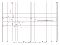
Let's jump in with a switching model of Voltage Mode Cotrol at 500KHz.

Screenshot from 2023-05-02 15-54-18.png


This is the startup,

Screenshot from 2023-05-02 15-56-49.png

Stabilty is key here. PLLs are hardcore so I'm going to spout words about how the loop in the above circuit is put together. In part that involves a wet finger in the air but in this case the loop is crossing over at FS/PI with FS being the switching frequency of 500KHz so in this case FCO is about 160KHz. kees52 knows of this as being The Nyquist Limit.

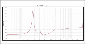
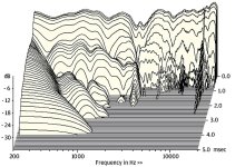
Once that is over we get our 1KHz Sine Wave,

Screenshot from 2023-05-02 16-06-00.png


And do an FFT on it to see how grim things might be,

Screenshot from 2023-05-02 16-08-27.png


The level of grim is -93dB. Of course this is a LTSpice model so in the real world things are likely to be dirt.

Right. That's an introduction. Next up I'll add some words about what the circuit bits are and what they are doing, will be long and may make no sense, and also drop a Linear Model of the loop to demonstrate the loop gain. Also the same for the switching model as described by,

https://ltwiki.org/LTspiceHelpXVII/LTspiceHelp/html/Bode.htm

The title is,

Extracting Switch Mode Power Supply Loop Gain in Simulation and Why You Usually Don't Need To

I kind of disagree with the bit in bold. If you have time to twiddle your thumbs it makes for a great insanity check.

Right! That's it for now. Laterz.

Attachments

Triac trouble

Evening all,
Please help me understand this scenario. I have build this circuit to drive a smallish transformer. 220Vac input on primary and 22VAC output on secondary. The primary resistance is about 34 ohm. This is the circuit that I have used. I'm using a BTA16-600BW triac and the circuit works OK. But what confuses me is when I test the output of the transformer using the triac control then I can adjust the voltage from about 8VAC to 22Vac which is good, but when I connect the secondary output to a rectifier bridge rectifier with a 0.1uf polyestercap just for testing then the confusion starts. The DC stays around 35VDC and cannot be adjusted much. I'm using a true rms Fluke to test. This confuses me completely. I have even removed the snubber circuit over the triac as it is not needed with these new triacs. I have connected the hot or live conductor to MT1 as this is what the datasheet say's which is different from this circuit.
plse help this flabbergasted man understand.

Attachments

  • IMG_20230510_123824.jpg
    IMG_20230510_123824.jpg
    827.9 KB · Views: 149

Douglas Self Preamp Linear Audio 5 kit, Boards Built and Tested

Everything in picture included. $200 pp fee-free shipped USA.

I built and tested this -- all controls work as they should. I did not test the XLR inputs and outputs (see below).

This PCB has the motor volume control. An extra 5k motor volume control is included, also an extra 5k "regular" pot. Also a remote controlled pot board that may or may not be adaptable to drive the 5k motor control.

The power supply board was populated with a similar spec transformer. Also included is an extra 300ma power supply. Extra ribbon connectors.

All IC's are populated. The XLR jacks were not soldered-in as it would probably be wise to wait until you have a chassis machined in case they need to be shifted ever so slightly to match the openings.

Also included is a case for the power supply board with connectors in "case" one wants an umbilical supply.

I found this preamp, while very nice, is more complex than my needs require, thus stopping any motivation I had to purchase a proper enclosure for it.

Attachments

  • d self (1).JPG
    d self (1).JPG
    586.2 KB · Views: 262
  • d self (2).JPG
    d self (2).JPG
    659.3 KB · Views: 260
  • d self (3).JPG
    d self (3).JPG
    582.1 KB · Views: 219
  • d self (4).JPG
    d self (4).JPG
    570.4 KB · Views: 208
  • d self (5).JPG
    d self (5).JPG
    511.4 KB · Views: 223

BR tuning: I must be doing it wrong

I need some help. I just finished building a new 3 way speaker, but the bass is . . . underwhelming.

I'm using a Dayton SD215A-88 in a 36.8L BR cabinet tuned at 31Hz (QB3 alignment). Using this port (area = 26.4cm2) WinISD calculated the port length to be 18.1cm, so that's what I started with. Unfortunately, the bass is not what I expected it to be. So I measured the port and driver responses (nearfield) and summed them, with the port response attenuated -7.2dB to compensate for the surface area difference compared to the driver. I did this for the port length calculated by WinISD (~18.1cm), and also for 16.0 and 13.5cm. This didn't improve things. It seems it's not a port tuning issue, but rather lacking performance from the driver.

I attached the REW file containing the measurements for three different port lengths. Does anyone have a clue why the bass is rolling off so soon?

This is the summed response (driver+port) for the WinISD calculated port length. There's a huge dip in the critical area.
Summed_Response.png

Attachments

Can someone help with Mark Levinson JC-2?

Is there someone out there who either is a qualified technician or knows
one in Atlanta? I came to the forum because of a problem with my
JC-2 preamplifier. I see from the discussion there that a posted schematic
is either correct or not correct. Sorry, I am confused. Then again, I'm
not a technician. The phono preamp in the thing is apparently blown-
can someone help me get this thing back on its little rubber feet again?

Thanking you all in advance.

AAP

Fender Champion 110 Loud Pop When Turning On Or Off.

I just bought a Fender Champion 110 and have a couple of issues.

- When I turn it on or off it makes a really loud pop - doesn't matter if volume is all the way up or all the way down.

- Additionally the reverb does not vary with any setting of the reverb pot - there is a minimum of reverb - barely noticeable. If I bump the amp the springs in the reverb tap together and make boinging noise till they settle down.

Appreciate any ideas, especially on the popping when turning on and off. Concerned it may eventually damage the speaker.

Potential GB for Toshiba Dual JFET Heatsink 2023

Ever since our last GB for these popular TO92 heatsinks, we have been asked umteen times.
https://www.diyaudio.com/community/threads/toshiba-dual-jfet-heatsink.135359/

And recently, they were offered at Swap Meet for 4.5x the original price, with postage on top.

To prevent this from happening again, we shall consider a new GB for 2023.
This depends on :

How much interest (say minimum 100 pcs in total per type) ?
What price we can get them made now (wages has gone up worldwide, since Corona and war) ?

We shall only know price after mid February, when Chinese factories return to work.
But you can state your interest now.
We shall limit the offer this time to Type 0 & 1, see also previous GB thread.

page19001.jpg


Help us to help you by filling in a running list properly.
We shall not be filling in for you if you don't put your name on the running list.


Patrick

LC vs RC filter for supply decoupling

I've noticed that some advocate using separate transformers for each channel of a power amplifier. I presume the reason is better supply decoupling.
I'm unconvinced whether this is a better method of supply decoupling than using a single transformer an LC or RC filter for each channel.
I'm considering LC coupling (with a damping resistor) for each channel. In practice, is there any benefit of LC coupling vs RC coupling? One obvious benefit of LC is less power dissipation and better ripple attenuation. However, we're not making linear amplifiers due to their power efficiency.

Cambridge Azure 640a V2 - 3 Flashes

Dear All

I am new here and new to electronics. I have this amplifier - 3 flashes in protection mode, immediately after the relays click at power on.

I have cleaned all the hardened brown adhesive off it.

I have also read this (great) posting here which describes checking R42 and R48. These seem to measure fine. Not shorted, not open and within 10% of what they should be.

I also saw a post from somebody who had the same issue and the power relays were his problem, so I bought a couple (for pennies) and soldered onto a circuit board for the first time in my life! Didn't fix it.

I have searched the PCBs (both sides) and components for signs of scorching, or blown out capacitors. I also cleaned off loads of gungy adhesive from between the protection circuit risers where some foam was once adhered.

I have a 540a v2 service manual and have started to go through the resistors one by one to try and find the issue. So far, nothing.

Attached to this post are some photos and I would be really very grateful if somebody who understands how these things actually work, could point me in the right direction next.

Many thanks

Ross

Attachments

  • 20230503_153717.jpg
    20230503_153717.jpg
    570.7 KB · Views: 264
  • 20230512_155058.jpg
    20230512_155058.jpg
    318.1 KB · Views: 212

Dual LM 386 board based amplifier project

I purchased two LM 386 and a PAM 8403 amplifier boards locally in 2016 hoping to build my own chip amplifier. With the TEA 2025 connected and driving my desktop open baffles, I thought it good to connect the LM 386 and check it for sound. There are reviews all over the tube but how does in sound?

This is a follow on from this thread: New Sleek Chip amp project however that thread is ending with the TEA 2025 based system so it seems good to create a new thread. The design should be similar though:


https://www.diyaudio.com/forums/att...6d1516102314-sleek-chip-amp-project-amopl-jpg


At first listen it sounded harsh, and a little bright. I connected it to my open baffles and then to a large Sony mini-fridge type speaker, the ES 333 or something. Without any amplification (yes I tried that ) there was hardly any sound but with the amplifier the music was soft, distorted and muffled. Maybe it was the source, as CD-derived track and Deezer type streaming sounded better. It plays quite loud 70dB at 10 cm from the speaker front.

Sorry for the blurry pix - actual setup. There is a nice clear description of the lm386 here:

OK, so the amplifier project has started - this will go in the living room to drive my 'bookshelf' OB speakers. Enclosure design next.


Questions:
How do I improve the design? One reviewer suggested a large capacitor across power input to increase bass response.
How do I incorporate bass and treble controls into the design?

Lifetime Music Album Collection Project

Now that I have my equipment more or less sorted out I am looking for CDs to add to my collection, as well as online music. It can only get better from here. I need music to inspire me in my journey and I don't want miss any good songs.

The Desert Island Albums thread has already helped, with a song by Brian Ferry I have not heard before. More suggestions welcome.

As a first step I went online to look at the list of the best albums of all time, listed by Rolling Stones Magazine:
https://www.rollingstone.com/music/music-lists/best-albums-of-all-time-1062063/

The 500 Greatest Albums of All Time

https://www.rollingstone.com/music/music-lists/best-albums-of-all-time-1062063/

The search netted some albums that I turned out to like, or at least some songs. I have already mentioned Marvin Gaye's 1971 Album "What's Going On". I intend to
wade through the rest of them. Michael Jackson's "Off the Wall" sounded surprisingly modern, and I think I will be listening to it many times in the next few years. There are already albums like that for me, such as "Hotel California".

The problem is, and here I think forum members can help me, is to highlight albums that are not that well known, but are rare gems nevertheless. A set of review records came into my possession at one time, where I discovered many albums I liked, including Tommy Shaw's Ambition, PM, and John Martyn. PM, as is the case in point, put out a beautiful ballad called "Moonlight In Paris" which I link here: needless to say I will be seeking to buy this album.

For me, $100 spend on CDs is worth to me more than $ 100 spent on speakers, DIY being sort of an example pattern to follow: make your equipment, buy your music.

I don't want to miss any good music.

This day in music history:

Elvis Presley released his self titled studio album in mono on RCA Victor. The album spent ten weeks at No.1 on the Billboard Pop Albums chart in 1956, the first rock and roll album ever to make it to the top of the charts, and the first million-selling album of that genre. The iconic cover photograph was taken at the Fort Homer Hesterly Armory in Tampa, Florida, on July 31, 1955.
https://www.thisdayinmusic.com/

Dynaudio Contour 1.8 MarkII fixed

Ok. This may be a bit long winded but here it goes. Maybe 5 years ago I bought some Dynaudio Contour 1.8 speakers. The person had told me he modified the crossovers, or improved them. I would say the speakers never sounded quite right. It is possible that I was under powering them but they never sounded very exciting. Well I should say they didn't sound exciting at a low volume. They seem to love being played loud. I moved around a bit and they went from the living room into a room where I was using them as near field monitors. Yes I know probably not a good idea... Anyways I noticed that they did not go very low. I would say about 65 hz then they just rolled off. Which makes sense for a 6.5 driver. I tried different amps and tonight I just said that's it... I took one of the mid bass drivers out of the speakers. And now as a two way they sound great. Almost like a giant contour 1.3. It would seem that taking one of the woofers out would change the ohms from 4 to 8 on the woofer side, and the volume should drop. I actually just turned the treble down to flat and everything seemed to work. I don't know how to describe it but they always sounded a bit messy and now they are focused and more involving. Now I have a couple of nice drivers to put in the car. Discuss.

Power rail higher than usual

Hi.

I'm building a diy power supply intended to supply current to Naim Supernait 1 integrated amplifier.

So far, I've placed transformers in place, along with diodes, capacitors and RC filters. I've bought discrete regulators, relatively expensive, that are connected to the ends of aforementioned RC filters.

However, one of the discrete regulators outputs different voltage. Instead of 24V that are needed for naim circuitry, it's reading +25.2V.

I know that op amps wouldn't be particularly picky about their voltage, but would higher voltage damage the Naim's preamplifier circuitry?

Best regards,
Stefan
  • Like
Reactions: TonyTecson

Power Supply for 2 ACA in one Chassis

I have 2 ACAs in their own chassis from the kit. I want to consolidate them into one chassis, which will most likely be the Dissipante 2U. My last issue is the power supply.

Instead of having 2 power inputs on the backplate, what is the best way for each ACA to have their own 24v power supply? Would I use the Universal Power Supply in the DIY store; and how would I go about adapting it to my situation?

Thanks!

For $200, can anything beat Pyle PH612 + JBL 2408H-1?

A few years back I bought a single JBL 2408H-1. To my eyes, it's basically a BMS 4540ND with a different phase plug.

I put it back on the shelf and forgot about it.

This week I've been doing some measurements of various waveguides and compression drivers, and noticing that the 2408H-1 plus the Pyle PH612 just keeps winning. In the words of The Iron Sheik, the JBL takes one look at my compression drivers and tells that "I will humble you."

And then it does.

I'm too lazy to upload all the measurements I made, but here's what I've noticed:

1) The 2408H-1 is insanely efficient. At the low end of the spectrum, it's limited by the diaphragm size, but above 2000Hz? YOWZA. This thing will rip your ears off.

0JBrStx.jpg

Here's a comparison of the JBL versus the Tymphany. Admittedly, a different waveguide. But the extra SPL above 2000Hz is noticeable. In particular, note that it's TWELVE dB more efficient at 20Khz. I think this is due to the new phase plug in there, basically same phase plug that's on the D2430K that costs five times as much. I really do think you're getting 80% of the D2430K performance for 20% of the price.

2ixPaHK.jpg

Here's some unequalized polars on the Pyle PH612. Purty!

Some caveats :

1) it's a screw on compression driver, so good luck finding waveguides that will fit. The Pyle PH612 and it's Dayton clone will work.
2) It won't go as low as the Tymphany or the B&Cs. You lose surface area when you go from a dome to a ring.
3) The PH612 has a nasty gap in the throat, you have to fill it in with Mortite to get curves like I've posted


Long story short: Let's give the 2408H-1 some love! It's a really nice compression driver that nobody is using.

Mark Levinson 333 does not power up

Hi

I need help diagnosing a problem with my ML 333:

I keep the amplifier always on stand-by. Today there was a sound similar to a capacitor discharge and the amplifier went from standby to off. No smoke, no fire. As I was wearing headphones when that happened and I did not use the amplifier at that time I am wondering why such a sound would come out of the speakers. So perhaps it was noise coming out of the amplifier (never experienced that before, though...)? At that moment I was not able to identify the source.

I disconnected the power cord, let the unit sit for one hour, re-connected the power and pushed the power switch. I heard the initial click of the power relay and then the unit went back to off (no blinking power LED at the front panel). Pressing the power button again did not result in any action (no more relay click).
I checked all loudspeaker connections for short etc., no issues. Again: When this happened the 333 was on standby.

The unit was recapped and checked/updated by an authorized ML repair shop approx. one year ago and was working fine until today.

I am quite experienced with Audio amplifier repairs but so far resisted on working on the ML due to the difficulty in obtaining parts. However, as I am not able to spend another $1,000 - $1,500 for another repair I am hoping that someone on this forum can provide me with some guidance on how to diagnose this problem.

I also do not have schematics, although I found some docs on this forum about the 336. Not sure of I can use them here.

Any support is greatly appreciated. Thanks!!!

Help with schematic

Recently I was able to get the schematic of my amp, a Pioneer A757. While I do have some basic understandig of amplifiers, I am by far not an expert, so if somebody could give me a few hints on how this schematics works, I would highly appreciate it.

I am also interested in mods/tweaks to improve the sound, if you see any oportunity in this respect. I like the sound of the amp, but it is a bit on the "dry" side for me - I'd have some more warmth, even at the cost of more distortion.

I find the schematics itself also pretty interesting, thoroughly in the style of late 80's - lots of components. I understand that the PA0016 IC is responsible with the biasing of the power stage, but I have really no clue what it really does - couldn't find a datasheet.
I also don't see a global feedback loop: there is one starting BEFORE the final stage to the diff amp, but I might oversee something there.

Later edit: there is global NF, I just missed it. The point where R243, C109, R115 get together is connected to the output of the amplifier.

Attachments

  • pa757bw4.jpg
    pa757bw4.jpg
    72 KB · Views: 3,304

Notes from an Audiophile with deteriorating hearing

It is a sad fact that our hearing deteriorates with age. Due to a tumour on my auditory nerve, hearing , both loudness and frequency response, on my Left side is worse than the Right .
I bought two three band tone control kits, so that the frequency response and volume could be varied independently. The conclusion was that the only variable needed was the balance between L & R. The output from the tone control fed a 1 Watt Class A headphone amp.
Various headphones were tried: An expensive (£120) over ear : a 50 year old pair of Pioneer on ear: a pair of ex Sony Walkman phones, but best of all were a pair of Philips ear buds, followed a close second by the Pioneers.
Would like to " hear" from others in a similar situation.

Grounding half of amplified balanced signal

So I am building a simple portable amplifier that has some peculiar setting as follows.

Amplified signal output from a DAC/AMP that has both balanced and single-ended outputs then goes into 2x LM386 boards, which are powered separately by 2x 9v batteries.

The amplified output signal needs to include 1x single-ended & 1x balanced (this is what I need). At the moment I am using 1x LM386 for each channel and L-/R- are shorted to input ground to create stereo output per the attached diagram (pardon my poor artistry skill).

The setup is running just fine, however since the 2 LM386 boards have to be separated at power supplies how would I wire them for an external DC supply? I guess sharing the same ground is impossible.

Additionally, is there any class D that can do half-bridge, or ground-referenced like the LM386 or TDA2030? I would like to improve run-time of the 9v batteries.

Attachments

  • diagram.png
    diagram.png
    31.7 KB · Views: 148

Converting .f3D (Autodesk Fusion 360) to DWG or DXF file type.

I'm using Autodesk Fusion 360, but exporting as DWG or DXF format is greyed out.
Using instructions to export as DXF, I did create a file with the object's outside dimensions, but the surfaces were blank and devoid of any details.

Currently, the application can export .f3d, 3mf, fbx, obj, skp (Sketchup files), smt, STEP, STL and USD. 😒
Is there a conversion tool that can accomplish this?

Effective Mass Method

Would a more accurate effective mass come as a result from the calculations below?

attachment.php


Three mass elements with horizontal and vertical axes on the centroids, with axes on the pivot of the wand.

attachment.php


Find I for the CW around the centroid, and sum with the value found with the parallel axis theorem through the pivot.

Same for the Wand and Cart, sum the results.

Confirming with a digital twin, and will post that once done.

At first glance, it seems the CW might have a bigger contribution to the overall inertia of the tonearm compared to calculating the CW as a point mass, if I'm seeing this right.

attachment.php


attachment.php


This is still an approximation, and it's possible to model a wand with variable mass distribution, by splitting the wand into multiple mass units to sum.

A possible way to use this for the wand would be to substitute the COM for the centroid, as both have an equal distribution of mass. CW and Cart should be fine, as is.

Both methods for horizontal and vertical are shown, as this could be a stepping stone for me to calculate the horizontal EM for PTTs, what I'm really after.

I'm open to corrections and guidance if I got something wrong.

Attachments

  • TA.png
    TA.png
    133.1 KB · Views: 1,739
  • CW.png
    CW.png
    77.4 KB · Views: 1,687
  • Wand.png
    Wand.png
    83.5 KB · Views: 1,772
  • Cart.png
    Cart.png
    82.1 KB · Views: 1,905

Driver cloning

I have measured the magnet parameters of a woofer at my friend’s home. We obtained the “Tesla” and “Weber” values. Unfortunately, we don’t have T/S measurement equipment. But, we know the physical parameters of the driver; 10” diameter, rubber surround, polymer cone, 50 mm. voice coil, 9.4 dc ohms. Based on these info, is it sufficient to clone this driver? Let’s assume cost is affordable for the Chinese/Taiwanese manufacturer. Actually, I don’t want identical driver, but at least, similar.

CounterPoint NPS-100A

Dear folks,
I took this amp from my late father. I want to check the condition of the amp and adjust input voltage from 110V to 220V.
I've checked transformer wiring and it is not difficult. However, I am concerned that there may be other effects after changing the voltage.
CounterPoint NPS-100A has three point of trim adjust. But I don't have any document. How can I get a service manual for this amp?
Or does this amp have a similar circuit to the NPS-200? I only have schematic diagram of NPS-200.

Any comment would be very helpful.

Stanley

F4 vs F5T?

I had the F4 built, fixed, biased bla bla bla and now working with the AudioResearch SP9 whose 20db output doesn't really make it, the BA-3 based preamp done but has to be fixed in a hum affecting it but off of testing doesn't seem to add much juice to drive the JBL L220 (90dbW/m) to their fullest, I love those speakers even tho I am a bass reflex fan and they are huge and looking like caskets (...), the easiest would be to give them away and get something smaller and a little more efficient to live happy with the F4 but, just in case, wondering if the DIY thing rises again, what would the F5T sound like compared to the F4? I gotta admit I miss the tube harmonics a bit...

Thanks
Projects by fanatics, for fanatics
Get answers and advice for everyone wanting to learn the art of audio.
Join the Community
507,689
Members
7,884,368
Messages

Filter

Forum Statistics

Threads
406,048
Messages
7,884,368
Members
507,689
Latest member
Giannikos