This is my first diyAudio post about my recent design and build of quirky loudspeakers. See
my recent introduction for brief background about me.
This will need to be an extensive story to give you the full picture of my project. Feel free to jump to the section you're interested in.
I designed and build two versions of this kind of subwoofer, and this post will be about the second version, hence the "version 2" in the title. A post about the smaller "version 1" might come later.
 Background
This idea of mine was born out of the last dull, depressing darkness of the Swedish winter. It has been 20+ years since I build a decent loudspeaker on my own, and suddenly this passion came washing over me again. It probably started when my now retired Harman Kardon active speakers started failing, and after trying to repair and revive them simply gave up. Suddenly I was without quality sound in my 88 m² apartment and my restless engineering brain started humming in 200 radians per second to find a solution. 🙃
I just recently found
SoundImports EU (apparently the "Parts Express" of Europe!?), which offers an impressive DIY assortment for appealing prices, and ships fast and cheap to my area. I needed a subwoofer, and spontaneously bought the
Dayton Audio 6-1/2" Down Firing subwoofer kit, thinking the specs looked to fulfil the needs of my living, fair price, and the box build (well, assembly of pre-cut boards) will be simple and quick. The subwoofer kit was most of that; it makes a lot of low-end noise for being a 6.5" driver. But my ears were not satisfied! So I started researching some more exotic subwoofer builds. I needed a design that would stimulate not only my ears, but also my brain cells during design, and also something different to satisfy my need for novelty.
My prior background in PA-loudspeakers makes my judgement biased; Long time ago I owned setups of 15" bass-reflex, 15" folded horns and 2x18" (pseudo)-horns to cover the low-end of my sound rigs. And those were driven by 19" rack professional amplifiers with power ratings in the kilowatt area. I loved the deep rumbling and physical sensations this setup could produce.
Reality check: I now own and live in an apartment in a multi-tenant house. Even if I would fit a 15-18" subwoofer at home, my skewed audio taste would probably get me evicted or at least throw my reputation among neighbors down the basement. So, I needed to let go of my comfort area: PA-class woofers, but I wanted most of the features they could offer!
Subwoofer requirements
Trying to list what I was aiming for in terms of end results
- Great low-end, sub-woofer response:
- Flat and loud subwoofer response, say 30-100 Hz ±3 dB.
- Decent phase response or group delay within the target frequency range.
- Apartment-friendly, semi-portable design (I need to move it in and out of my 3rd floor apartment on my own).
- High acoustic efficiency (avoid the need of another kW amplifier).
- I want to be able to do all engineering design by myself, using free or easily available tools/software.
- The design needs to be quirky/novel/different to satisfy my restless engineering mind.
- Assembly of the final speaker needs to be relatively clean and un-complicated:
- I'd like to do all work in my apartment and/or electronics lab.
- Avoid using wood as building material, as cutting it is too dirty for my facilities.
During my research (well, watching YouTube, visiting many obscure audio pages seemingly designed in the 90's, and scrolling through this excellent forum), I was captivated by two main categories for a custom speaker design, listed here with my conclusions and pros/cons:
- 6th order, dual reflex, triple-chamber parallel bandpass with small (5-8") drivers:
- Plus (quirky): This is not a very common design!?
- Using three different tuning frequencies to offer a wide frequency response:
- Design with all three chambers tuned differently (the default design would have two identical chambers, I assume).
- Plus (novelty): I never found anyone publishing a 6thr order enclosure with three intentionally different tuning frequencies!
- Design with two different drivers in the same dual-chamber design to achieve wider frequency response and/or better group delay.
- Plus (novelty): Also never found this solution online!
- Using small drivers would allow for a low-height rectangular cuboid that I could possibly hide under a sofa or other furniture.
- Minus (build): The box will be a regular box that is best built using wooden panels.
- Inspiration:
- Horn-loaded designs
- Front-loaded folded horn
- Plus: Ticks most boxes for acoustic performance.
- Minus (novelty): I owned them before, quite common woofer design.
- Tapped horn
- 3D-printed horn-hybrid / wave guide
- Quarter-wave transmission line
- Transmission lines are basically straight-line horn designs, I learned.
- Minus (novelty): Common layout in some high-end, full-range speakers.
- Minus (build): Usually built with wood panels as square boxes.
- Non-rectangular cuboid transmission lines:
- Inspiration:
- Wait WHAT!? Standard pipe fittings can make a good transmission line enclosure!?
- What if it scaled up...? Hold my beer... (all boxes ticked)! 🤩
Engineering design
I decided to use a quarter-wave transmission-line enclosure, based entirely on standard pipe fittings! Because in theory it is supposed to work just great, AND just the idea of it sound ridiculous. That's just what I was looking for!
I read numerous guides and theory for transmission line enclosures (hereafter: TL), e.g:
quarter-wave,
diysubwoofers.
I learned quickly that
Hornresp is a great tool to use for evaluating potential designs (my deepest gratitude to the Hornresp team for offering this great piece of software!).
SpicyTL is another very promising software, but haven't come to terms with those libraries quite yet, despite being based on the SPICE software, which I'm previously familiar with.
How big?
The high-level design of a TL subwoofer enclosure starts with two parameters: Lowest resonance frequency and mouth air speed at max intended SPL. The former is easy to approximate: "Quarter wave" means that one-quarter of the longest wave needs to fit inside the line. Deep sub-bass down to 20 Hz would be lovely, but 343 m/s / 20 Hz / 4 = 4.3 m, which would be inconvenient to squeeze into my apartment with 2.5 m ceiling height without folding (complicated build). What about setting the max line length to 2.5 m then, as in using my full height of the ceiling walls? 343 m/s / 2.5 m / 4 = 34.3 Hz. Well, this is not too bad, considering I just saved one 180° fold and 1.8 meters of piping! Regardless of the TL lowest resonance frequency, the selected driver needs to be able to work properly at these levels.
The air speed at the line mouth is important because high air velocities will cause turbulence at high sound levels, which might create huffing, puffing and whining sounds, or just simply "chuffing". Carefully designing the mouth geometry could alleviate much of this problem, but in my case, I will need to accept the shape and geometry of standard pipes! I assumed a guesstimate of 10-15 m/s for maximum air speed at the mouth. Knowing this number makes it easy to calculate a suitable diameter for the TL. I made some simple estimations by calculating the maximum volumetric air flow at the mouth (cross-section area * max air speed), and comparing that to what a suitable driver would be able to generate, given by TS-parameters Xmax * Sd (with care taken to unit conversions).
Off-the-shelf piping comes in highly standardized diameters. I browsed through dozens of product catalogs of both plastic, paper and metal pipes from my local hardware stores, and decided to go with large plastic pipes. The relevant sizes for a sub-woofer that I could easily buy are (outer) diameters 110 mm or 160 mm. This types of plastic pipes are normally used to carry sewage water inside- and between buildings. This makes a great excuse is the designs turns out to sound like ****! 🤪
I decided quickly that I wanted to build a TL without any need for an additional "throat chamber" made as a typical rectangular box (again, no wood, please!). This is a key difference from the inspiration I got from the typical
El Pipe-O subwoofers. Basic design rule: Use only standard pipe fittings!
The next challenge I encountered is that a simple straight line made with smooth, hard linings will sound like an echo chamber. Therefore, careful consideration must be put into the type and amount of damping. Thankfully, Hornresp allowed me to evaluate both placing, properties and amount of damping material through simulations. More about the outcome later.
Driver requirements
From the TL-design sources mentioned above, I read that suitable drivers for TL enclosures, in terms of TS-parameters would need a low Fs (quite obvious for a subwoofer design!?), but even more importantly, low Qts (effectively meaning low Qes!?). Attention to the risk of over-excursion is important with low-Qts drivers. This might, or might not, be a problem in a TL design.
I made a list... well many lists, of potential drivers to use in my design. I didn't want to spend a fortune, in case this experiment failed. But I still wanted a great fit in characteristics (TS-parameters) for a TL. As a surprise, the very same driver included in the budget subwoofer kit I first bought from SoundImports (DCS165-4) turned out as the best budget alternative driver for a TL-design, thanks to its reasonably low Qts of 0.34!
Here's a list of my four favorite drive candidates:
- Dayton Audio DCS165-4 - 6.5"
- SEAS CD22RN4X - H1192 - 8"
- Dayton Audio UM8-22 - 8"
- Dayton Audio UMII8-22 - 8"
I did plenty of simulations in Hornresp. Actually I enjoyed this process a bit too much, since my profession is simulation of non-linear mechatronic systems. I found Hornresp to be a very satisfying tool that tickled most of my geeky traits. Long story short, I decided to build two different pipe-sub designs. One based on the 6.5" DCS165-4, and one design based on the 8" UM8-22 (first generation, which seems to be out of production now). The 6.5" version became "version 1", which I will eventually probably write another post on. This post will continue about the 8" version.
The selection of driver is made not only on the TS-parameters, price and availability, but also on geometric details like exact baffle size. Since I am basing my entire enclosure on standard pipes, I really want to maximize the cone area able to fit onto or into a standardized pipe! I would not allow valuable millimeters get wasted by a sloppy mechanical fit! Many driver candidates got rejected on the simple basis that their data sheets did NOT include precise measurements of the baffle, mounting holes or cutout diameter!
The selected "Ultimax UM8-22 Subwoofer" is a pretty sturdy piece of driver at 6.9 kg, dual 2", 2 Ohm voice coils and ±16 mm of linear excursion and specified at 300 W rms power!


As soon as I got my driver delivered, I measured its TS-parameters using a
DATS V3. Maybe not surprising, but the TS-parameters were deviating from the datasheet. This would probably mean that the TS system will not behave as simulated. But taking this into account in the design process is one variable to much to handle right now. And in best of cases, the actual TS-parameters will stabilize close to the datasheet values after some "burn-in" of the driver.
Transmission Line Layout
A long straight line at ~2.5 m, and enough diameter to support the maximum air flow of the driver. Sound simple!
But... I learned through simulations that a straight TL design without any tricks will have a quite narrow bandwidth in frequency. For a design reaching just below 30 Hz (±3 dB), a destructive interference pattern would show up at 90 Hz (basically 3 * lowest resonance), and severely reducing the sound pressure output near this upper range.
I found a trick, which is to mount the driver "offset" along the TL. According to theory, and simulations, this will alleviate the first order of destructive interference patterns in the frequency range. I experimented a lot through Hornresp simulations, with the rule of thumb that a good driver offset seem to be 1/3 of the full TL length away from the closed-end.
This trick does not only produce a very appealing frequency response, but it also opens up for a few more positive design options (which "version 1" does not have):
- The driver does not need to be mounted on the closed-end of the TL
- The TL closed-end can rest directly on the floor
- No need for protection or vertical offset of the TL to allow the driver cone coming close to the floor
- This effectively saves about 200 mm of dead vertical space, which can be used for the main TL length instead. Great when the vertical space is the limiting factor for the design!
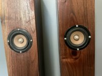
- The driver can instead be mounted facing outwards, which is (in my opinion) esthetically preferable.
Hornresp layout:


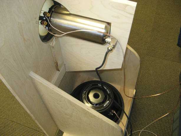
The UM8-22 driver has a baffle cut-out of 189 mm (according to drawing), which is obviously too large to fit in a 160 mm pipe. Hence, an adaptor is needed. After scrolling through many products of sewage pipes, I found a standar component named "chamber rodding tee", which is available as 160 mm diameter for the main line, and 200 mm for the inspection inlet. The UM8-22 driver fits perfectly into the take-out section with only "minimal" changes to the plastic structure. The rodding tee pipe comes only in the color Obnoxious Orange, so I spent some time learning how to paint Polypropylene plastic.

The main TL is constructed out of "premium" drainage pipes from
Geberit: Silent-PP. I picked these pipes mainly because of the aesthetics (available in black), but almost ironically, these pipes are intended for "sound-optimised installation of drainage systems" 😄 What it actually means is that the wall thickness is higher than the pipe standard requires, which increases the stiffness of the pipe, and hence reduces resonances in a typical drainage installation.
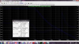
Simulation results
Hornresp results are presented assuming eight space radiation. Datasheet TS-params are used for UM8-22.
Acoustic output at 1 W (left graph), and max power 300 W (right graph). Sections of bold red means excursion-limited output.
Group delay (left graph). Mouth air speed at 300 W (right graph).
End results
So far, this unit has been in operation for a few months in my apartment. It plays LOUD and DEEP! Probably generating slight annoyance in my neighbors, but I'm till not evicted 😄.
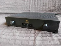
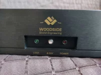
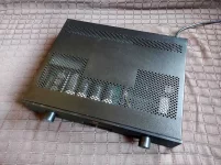
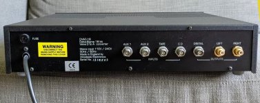
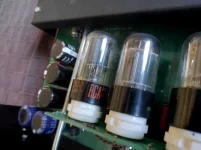
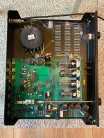
It is currently hooked up with the dual 2 Ohm voice coils in series and powered by a tiny 100 W class-D amplifier, which is capable of generating more rumbling than I dare to continuously play in a multi-tenant house.
I do realize that my living room most likely has strong constructive resonances around the lower end of the pipe-sub's frequency range, which might make it sound more impressive than it might be in a resonant-free environment. Though, I recently took my "pipe-sub v2" (also known as "Bazooka-sub", or "Super-Mario-Woofer") to a workshop and hooked up to a more capable amplifier to test it's capability in a bigger room, and an environment where people wouldn't mind some loud noises. I can only say it did not fail to surprise me, as it continued to played deep and loud with linear excursion (and surprisingly low amounts of chuffing and/or air leakage) for as long as the amplifier's power supply could support us.
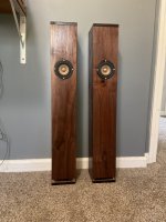
Super-mario-woofer!?

Full-size image of end result:
I'm looking forward to your feedback on this project!


 , remember that this is a mid- to lowfi project. For fun. Low cost.