Tandem regulators are a special class of two-quadrant regulators, in which the series and shunt members do not simply work side-by-side, but cooperate in an active, synergetic manner to sublimate the performances.
I have given details about the principles
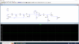
here (many other topologies are possible, but for the amplifier I will concentrate on a particular one):
These circuits not only work superbly as normal regulators, but thanks to their stiff, accurate output and their source/sink ability, they also do wonders in virtual ground generation
This begs the question: could they work as an output stage?
The answer is yes, and they have exceptional open-loop properties: milliohm output impedance, 0.01% linearity, >>10MHz small signal bandwidth, a fixed, stable and deterministic quiescent current, a <10mV I/O offset, etc.
They look like the dream OP stage, so what's not to love about them?
A few things, unfortunately: there is always a fly or two in any ointment, and this circuit is no exception.
The most obvious quirk is the negative input impedance: around -200 kiloohm at AF frequencies. Not a big deal you might say: connect a 180K in parallel, and the impedance becomes positive, in the megohm range.
You can even use it to change the unity gain buffer into an amplifier: connect the source through a 100K resistor, and the buffer becomes a gain of 2 amplifier; not something I recommend, though.
In addition, the negative impedance is dependent on the Hfe of the input transistor, and since it has a finite Ft, the Hfe and negative resistance will decrease with frequency, requiring additional measures.
The topology also has a more subtle, but annoying feature: a right half-plane zero.
If you look just at Q1, Q5, Q6, ignoring the rest of the circuit, you see an inverting amplifier followed by a common collector buffer, but the whole circuit is in fact a buffer: it does not invert.
This means that for a positive step at the input, the circuit will first try to behave as an inverter, until the ring of the other transistors retakes the control.
Another, more down to earth peculiarity is the difficulty to simulate it reliably: the circuit relies on NFB for DC stability, and positive FB for error correction. The EC (it is a true one, not some NFB in disguise) eliminates all the first-order imperfections.
The rest is a mix of higher order effects, some of which are not well covered in spice simulators and models, which concentrate on the most common effects seen in "ordinary", more conventional circuits.
This means that the sims tend to deviate significantly from the reality: the results are no better or worse, they are simply different, inaccurate.
That is certainly not a valid reason to discard an effective, valuable topology, but it requires more physical verifications.
Manufacturers certainly have better tools at their disposal, like Mextram, and the equivalent of LTspice used internally by ADI is certainly more sophisticated than the public version, but we have to make do with what we have.
Note that this amplifier is just a proof of concept, not a fully-fledged project like the Circlophone, the Old-Fashioned, etc. These projects have been thoroughly studied and designed to be tolerant and almost fool-proof.
This is not the case with this amplifier: you can certainly listen to music through it, but to make it into a serious project would require some homework.
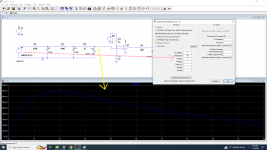
The amplifier can operate in open or closed loop. This is the THD in open-loop mode: 0.04%:
The physical prototype does a little better, 0.03%. The linearity is strongly dependent on the "scaled" matching, and the matching of D1 to Q4 (I have used a diode because using a power transistor to work as a diode looks excessively luxurious).
Various resistors fine-tune the correction: R11, R12 and R14 which forces a positive impedance for the opamp output. As opamp, I have successfully tested NE5534, LT1028 and HA7 2505.
When the GNFB is in service, the THD becomes unmeasurable with my ST1700: it is probably of the order of the ppm, or lower.
Here is the impedance, also open-loop:
The real circuit is slightly worse, at ~10milliohm.
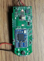
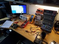
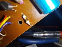
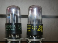
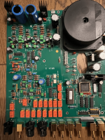
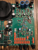
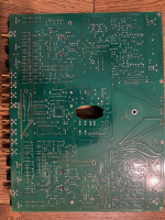
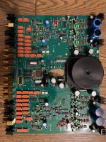
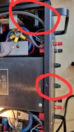
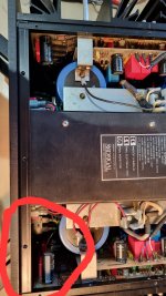
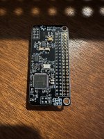
This is the actual prototype:
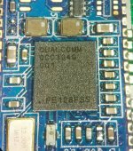
Here are some pics of the prototype:
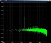
And finally, the squarewave response showing the effect of RHP zero on the rising edge
The Tandem stage is very useful building block is you are prepared to develop an amplifier around it.
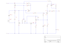
Here is a description of the circuit:
For simplicity, it uses an opamp for the front-end. This limits the output power to ~10W/8ohm.
Q5 and Q2 do the buffering work, and Q4 senses the current through Q2, scales it and applies it to Q5. Since the emitters of Q2 and Q5 follow an analogue I/V relationship, the arrangement eliminates the exponential curvature of the characteristic, linearising the doublet; in theory at least: Q2 and Q5 need to have an intersex, scaled matching. A tall order, with different technologies, junction areas electrons holes mobility, etc.
To fit the curves more closely, corrections are added.
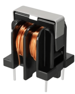
The components selected for the prototype were mainly chosen according to my stock. I have gone overboard with the transistors: the 2N6702 has a Ft of 200Mhz, practically a VHF PA.... The D45H11 is a bit more reasonable at 50MHz, but the BC638 and BD135 from TFK are in the 200~300MHz region. That's asking for trouble, and trouble I had: it is the reason for the hefty ferrite bead.
The first prototype on a breadboard used more sensible BD203/4, had no stability issues and still performed quite well.
The capacitor across the BYV71 might look strange: it is a fast diode, and normally the forward recovery characteristic is excellent, yet it was insufficient in this case, because the circuit pushes some components into their limits


.jpg")